US1854631A - Rotary cutter - Google Patents
Rotary cutter Download PDFInfo
- Publication number
- US1854631A US1854631A US332834A US33283429A US1854631A US 1854631 A US1854631 A US 1854631A US 332834 A US332834 A US 332834A US 33283429 A US33283429 A US 33283429A US 1854631 A US1854631 A US 1854631A
- Authority
- US
- United States
- Prior art keywords
- blade
- carrier
- pin
- groove
- rotary cutter
- Prior art date
- Legal status (The legal status is an assumption and is not a legal conclusion. Google has not performed a legal analysis and makes no representation as to the accuracy of the status listed.)
- Expired - Lifetime
Links
- 230000013011 mating Effects 0.000 description 2
- 210000001217 buttock Anatomy 0.000 description 1
- 230000037431 insertion Effects 0.000 description 1
- 238000003780 insertion Methods 0.000 description 1
- 239000000463 material Substances 0.000 description 1
- 239000002184 metal Substances 0.000 description 1
- 238000005555 metalworking Methods 0.000 description 1
Images
Classifications
-
- B—PERFORMING OPERATIONS; TRANSPORTING
- B23—MACHINE TOOLS; METAL-WORKING NOT OTHERWISE PROVIDED FOR
- B23D—PLANING; SLOTTING; SHEARING; BROACHING; SAWING; FILING; SCRAPING; LIKE OPERATIONS FOR WORKING METAL BY REMOVING MATERIAL, NOT OTHERWISE PROVIDED FOR
- B23D77/00—Reaming tools
- B23D77/12—Reamers with cutting edges arranged in tapered form
-
- Y—GENERAL TAGGING OF NEW TECHNOLOGICAL DEVELOPMENTS; GENERAL TAGGING OF CROSS-SECTIONAL TECHNOLOGIES SPANNING OVER SEVERAL SECTIONS OF THE IPC; TECHNICAL SUBJECTS COVERED BY FORMER USPC CROSS-REFERENCE ART COLLECTIONS [XRACs] AND DIGESTS
- Y10—TECHNICAL SUBJECTS COVERED BY FORMER USPC
- Y10T—TECHNICAL SUBJECTS COVERED BY FORMER US CLASSIFICATION
- Y10T279/00—Chucks or sockets
- Y10T279/17—Socket type
- Y10T279/17128—Self-grasping
- Y10T279/17171—One-way-clutch type
- Y10T279/17188—Side detent
- Y10T279/17196—Ball or roller
-
- Y—GENERAL TAGGING OF NEW TECHNOLOGICAL DEVELOPMENTS; GENERAL TAGGING OF CROSS-SECTIONAL TECHNOLOGIES SPANNING OVER SEVERAL SECTIONS OF THE IPC; TECHNICAL SUBJECTS COVERED BY FORMER USPC CROSS-REFERENCE ART COLLECTIONS [XRACs] AND DIGESTS
- Y10—TECHNICAL SUBJECTS COVERED BY FORMER USPC
- Y10T—TECHNICAL SUBJECTS COVERED BY FORMER US CLASSIFICATION
- Y10T279/00—Chucks or sockets
- Y10T279/17—Socket type
- Y10T279/17761—Side detent
- Y10T279/17821—Set screw
-
- Y—GENERAL TAGGING OF NEW TECHNOLOGICAL DEVELOPMENTS; GENERAL TAGGING OF CROSS-SECTIONAL TECHNOLOGIES SPANNING OVER SEVERAL SECTIONS OF THE IPC; TECHNICAL SUBJECTS COVERED BY FORMER USPC CROSS-REFERENCE ART COLLECTIONS [XRACs] AND DIGESTS
- Y10—TECHNICAL SUBJECTS COVERED BY FORMER USPC
- Y10T—TECHNICAL SUBJECTS COVERED BY FORMER US CLASSIFICATION
- Y10T279/00—Chucks or sockets
- Y10T279/17—Socket type
- Y10T279/17923—Transverse pin
Definitions
- the invention has, among other objects, rear end portion of which is designed to fit D 10 blades are known to be subjected, the particuof a width to snugly receive the attaching or Y15 the complete removal thereof for renewal or ting engagement with the wall of a previouse0 Patented Apr. 19, 1932 UNrrEn STATES PATENT OFFICE'.
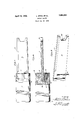
- Figure 2 illustrates that the forward porsecurely to a carrier to resist shifting under tion of the carrier 5 is reduced externally the influence of the strain to which such and'is provided with :a diametrical groove 6 lar means by which the blade is connected to rear portion of a blade 8.
- the single flat the carrier being readily releasable from blade 8 may be tapered slightly towardfthe binding engagement with the blade to allow forward end and has the opposite edges of the transverse adjustment of the blade or thereof sharpened as indicated at 10 for cut* resharpening. ly formed hole in metal or other material.
- one wall of body a rotary blade in which the cutting the groove 6 and the opposed surface of the portions thereof are extended substantial blade 8 are provided with mating transverse- 2o distances beyond the forward center hole of ly extending channels receiving a locking pin 65 the blade so that the blade may be resharp- 12.
- the pin receivingchannel in the wall ened a number of times without disturbing ofthe groove 6 is designated by the numeral such forward center hole, it being under- 14 and as shown in Figure 2 is slightly stood, of course, that when the blade is 'greater in cross sectional area than the mat- 25 mounted in a grinder for resharpening, the ing channel in the blade 8 so that the locking 70 aforesaid center hole is employed in conjuncscrew 16 may move the pin bodily into firm tion with a similar hole at the rear end of the binding engagement withl the blade to seat blade to allow of the rotation of the blade the blade in the groove 6.
- FIG. 1 is a fragmentary side elevation of engagement by a tool suitable for the purpose S5 4.5 forming a part of the invention. reamed.
- FIG. 2 is a fragmentary longitudinal believed to be clear that it is a simple ⁇ matter sectional view through the tool, to adjust the blade transversely of the carrier
- Figure 3 is a perspective of a cutting blade vto accurately center the same to the hole being i v 9o
- the transverse groove 6 extending entirely across the forward portion of the carrier and intersecting the axis of the carrier denes what might be said to be a pair of partly severed segmental blade engaging members and to avoid increased separtion of these segmental members under the influence of the strain accompanying the use of the tool the same are embraced closely by a ferrule 18.
- the ferrule 18 not only has the function of bracing the forward portion of the carrier, but extends over and substantially closes the ends of the groove 6.
- the ferrule 18 may be integral with the carrier 5 and in either case willbe provided vwith openings for the passage of the pin 12.
- the blade is provided with center holes 2O and 22, through the medium of which the blade may be attached in the usual manner to a grinder for the purpose of resharpening the oppositely located cutting portions 10. 1t is important to observe thatthe forward portion of the blade 8 is recessed rather deeply between the cutting portions 10 and that the center hole is in the linner wall of such recess so that the cutting portions of the blade are extended ysubstantial distances beyond the forward center hole. By reason of this arrangement, the tool may be resharpyenedV a number of times without disturbing the forward center hole.
- a rotatable support having the forward end thereof formed with a diametrical groove, a rotary4 blade having the rear portion thereof in said groove, a .laterally movable loclring pin parallel to and engaging said blade, said support being provided with a threaded opening, a screw threaded linto said opening and engaging said pinto force the same into binding engagement with said blade, said opening being extended out through the forward lend vof said support to afford accessto the screw from the forward end of the support, and a ferrule embracing the diametrically grooved forward portion of said support to hold the same against spreading.
- a rotatable support having the forward end thereof formed with a diametrical groove, a rotary blade having the rear portion thereof in said groove, a locking pin parallel to and engaging said blade, said support being provided with a threaded opening, a screw threaded into said opening and engaging said pin, said opening being extended out through the forward end of said support to afford access to the screw from the forward end of the support, and a tures.
Landscapes
- Engineering & Computer Science (AREA)
- Mechanical Engineering (AREA)
- Polishing Bodies And Polishing Tools (AREA)
- Drilling Tools (AREA)
Description
April 19, 1932.
L. sKr-:EL E1-l AL ROTARY CUTTER FiledvJan. 16, 1929 INVENToRs 4:9, M867/ fa 41h/713W, y (BJI ATTORNEY.
' 5 The invention has, among other objects, rear end portion of which is designed to fit D 10 blades are known to be subjected, the particuof a width to snugly receive the attaching or Y15 the complete removal thereof for renewal or ting engagement with the wall of a previouse0 Patented Apr. 19, 1932 UNrrEn STATES PATENT OFFICE'.
LEWIS sKEEL AND FRANK r. MILLER, or MEAnvrLLE, PENNSYLVANIA ROTARY CUTTER Application led January 16, 1929. Serial No.'332,-834.
This invention relates to rotary cutters In the drawings wherein for the purpose especially adapted for use in metal working of illustration is shown apreferred 'embodialthough not necessarily restricted to such ment of the invention the numeral 5 desiguse. nates a carrier in the nature of a shank, the
the provision of means by which the blade in a machine spindle.
of a taper reamer or the like may be attached Figure 2 illustrates that the forward porsecurely to a carrier to resist shifting under tion of the carrier 5 is reduced externally the influence of the strain to which such and'is provided with :a diametrical groove 6 lar means by which the blade is connected to rear portion of a blade 8. The single flat the carrier being readily releasable from blade 8 may be tapered slightly towardfthe binding engagement with the blade to allow forward end and has the opposite edges of the transverse adjustment of the blade or thereof sharpened as indicated at 10 for cut* resharpening. ly formed hole in metal or other material.
The invention will further be found to em- In carrying out the invention, one wall of body a rotary blade in which the cutting the groove 6 and the opposed surface of the portions thereof are extended substantial blade 8 are provided with mating transverse- 2o distances beyond the forward center hole of ly extending channels receiving a locking pin 65 the blade so that the blade may be resharp- 12. The pin receivingchannel in the wall ened a number of times without disturbing ofthe groove 6 is designated by the numeral such forward center hole, it being under- 14 and as shown in Figure 2 is slightly stood, of course, that when the blade is 'greater in cross sectional area than the mat- 25 mounted in a grinder for resharpening, the ing channel in the blade 8 so that the locking 70 aforesaid center hole is employed in conjuncscrew 16 may move the pin bodily into firm tion with a similar hole at the rear end of the binding engagement withl the blade to seat blade to allow of the rotation of the blade the blade in the groove 6.
about the longitudinal center thereof in the The mating channels for the reception of '30 usual manner. the pin 12 are extended out through opposite 75 Another feature of the invention resides in sides of the carrier for the insertion and rethe means by which spreading of the blade moval of the pin 12. As shown'in Figure 2, engaging portion of the carrier under the the locking screw 16 is threaded into the carstrain incident to the use of the tool is rier 5 at an angle to the axis of the carrier '35 avoided, and is provided with a sharply tapered trun- 80 In the accompanying drawings forming a Vcated forward portionfor pressure engagepart of this application and in which like ment with thelocking pin 12. numerals are employed to designate like y Therear portion of the locking screw 16 is parts throughout the same, `-constantly exposed and highly accessible for '4G Figure 1 is a fragmentary side elevation of engagement by a tool suitable for the purpose S5 4.5 forming a part of the invention. reamed.
the improved tool, of tightening or loosening the blade. It is Figure 2 is a fragmentary longitudinal believed to be clear that it is a simple `matter sectional view through the tool, to adjust the blade transversely of the carrier Figure 3 is a perspective of a cutting blade vto accurately center the same to the hole being i v 9o The transverse groove 6 extending entirely across the forward portion of the carrier and intersecting the axis of the carrier denes what might be said to be a pair of partly severed segmental blade engaging members and to avoid increased separtion of these segmental members under the influence of the strain accompanying the use of the tool the same are embraced closely by a ferrule 18. The ferrule 18 not only has the function of bracing the forward portion of the carrier, but extends over and substantially closes the ends of the groove 6.
The illustrated reduction in the diameter of the forward portion of the cylindricalcarrier disposes the outer surface of the ferrule 18 flush with the surface of the carrier. d
1f desired, the ferrule 18 may be integral with the carrier 5 and in either case willbe provided vwith openings for the passage of the pin 12.
As shown in Figure 2, the blade is provided with center holes 2O and 22, through the medium of which the blade may be attached in the usual manner to a grinder for the purpose of resharpening the oppositely located cutting portions 10. 1t is important to observe thatthe forward portion of the blade 8 is recessed rather deeply between the cutting portions 10 and that the center hole is in the linner wall of such recess so that the cutting portions of the blade are extended ysubstantial distances beyond the forward center hole. By reason of this arrangement, the tool may be resharpyenedV a number of times without disturbing the forward center hole.
Having thus described the invention what is claimed is:
1. In a reamer, a rotatable support having the forward end thereof formed with a diametrical groove, a rotary4 blade having the rear portion thereof in said groove, a .laterally movable loclring pin parallel to and engaging said blade, said support being provided with a threaded opening, a screw threaded linto said opening and engaging said pinto force the same into binding engagement with said blade, said opening being extended out through the forward lend vof said support to afford accessto the screw from the forward end of the support, and a ferrule embracing the diametrically grooved forward portion of said support to hold the same against spreading.
2. In a reamer, a rotatable support having the forward end thereof formed with a diametrical groove, a rotary blade having the rear portion thereof in said groove, a locking pin parallel to and engaging said blade, said support being provided with a threaded opening, a screw threaded into said opening and engaging said pin, said opening being extended out through the forward end of said support to afford access to the screw from the forward end of the support, and a tures.
LEWIS SKEEL. FRANK P. MILLER.
Priority Applications (1)
| Application Number | Priority Date | Filing Date | Title |
|---|---|---|---|
| US332834A US1854631A (en) | 1929-01-16 | 1929-01-16 | Rotary cutter |
Applications Claiming Priority (1)
| Application Number | Priority Date | Filing Date | Title |
|---|---|---|---|
| US332834A US1854631A (en) | 1929-01-16 | 1929-01-16 | Rotary cutter |
Publications (1)
| Publication Number | Publication Date |
|---|---|
| US1854631A true US1854631A (en) | 1932-04-19 |
Family
ID=23300058
Family Applications (1)
| Application Number | Title | Priority Date | Filing Date |
|---|---|---|---|
| US332834A Expired - Lifetime US1854631A (en) | 1929-01-16 | 1929-01-16 | Rotary cutter |
Country Status (1)
| Country | Link |
|---|---|
| US (1) | US1854631A (en) |
Cited By (1)
| Publication number | Priority date | Publication date | Assignee | Title |
|---|---|---|---|---|
| FR2435991A1 (en) * | 1978-09-18 | 1980-04-11 | Deutsch Fastener Corp | Rotary cutter for producing tapered hole in metal - has rectangular section blade with negative rake cutting edges with swarf removed by jet of cutting fluid |
-
1929
- 1929-01-16 US US332834A patent/US1854631A/en not_active Expired - Lifetime
Cited By (1)
| Publication number | Priority date | Publication date | Assignee | Title |
|---|---|---|---|---|
| FR2435991A1 (en) * | 1978-09-18 | 1980-04-11 | Deutsch Fastener Corp | Rotary cutter for producing tapered hole in metal - has rectangular section blade with negative rake cutting edges with swarf removed by jet of cutting fluid |
Similar Documents
| Publication | Publication Date | Title |
|---|---|---|
| US3945753A (en) | Drill bit device | |
| EP1370382B1 (en) | Profile turning tool | |
| EP0612575B1 (en) | Drilling tool | |
| US2645844A (en) | Toolholder | |
| DE2548870A1 (en) | GROOVING AND PARTING TOOL | |
| EP0984850B1 (en) | Cutting tool, especially plane blade head or plane blade shaft | |
| US1854631A (en) | Rotary cutter | |
| US2659962A (en) | Toolholder | |
| DE2140004A1 (en) | COUNTERING AND MILLING TOOL | |
| US2395570A (en) | Cutting tool | |
| US2245446A (en) | Cutting tool | |
| US2102478A (en) | Cutting tool | |
| US2418734A (en) | Tool holder | |
| US2659963A (en) | Toolholder | |
| US2508437A (en) | Inserted blade cutter | |
| US4011050A (en) | Cutting-off tool | |
| US2104604A (en) | Cutter clamping mechanism | |
| US2649818A (en) | Metal cutting tool | |
| GB380567A (en) | Improvements in or relating to milling and like cutting tools | |
| US2041587A (en) | Refacing tool for valve seats | |
| DE19717702B4 (en) | Portable planer | |
| EP0497257B1 (en) | Cutting-off device | |
| US1951100A (en) | Inserted blade cutter | |
| US3030829A (en) | Finishing and roughing bar | |
| DE19937738B4 (en) | Profile-turning tool |