US185459A - Improvement in hand-binders - Google Patents
Improvement in hand-binders Download PDFInfo
- Publication number
- US185459A US185459A US185459DA US185459A US 185459 A US185459 A US 185459A US 185459D A US185459D A US 185459DA US 185459 A US185459 A US 185459A
- Authority
- US
- United States
- Prior art keywords
- binders
- grain
- elevator
- belts
- gavel
- Prior art date
- Legal status (The legal status is an assumption and is not a legal conclusion. Google has not performed a legal analysis and makes no representation as to the accuracy of the status listed.)
- Expired - Lifetime
Links
Images

Classifications
-
- A—HUMAN NECESSITIES
- A01—AGRICULTURE; FORESTRY; ANIMAL HUSBANDRY; HUNTING; TRAPPING; FISHING
- A01D—HARVESTING; MOWING
- A01D37/00—Reaper-binders
- A01D37/02—Reaper-binders with receiving platform and binding apparatus but without elevating canvases
Definitions
- my invention consists of certain combinations and arrangements of me-v chanical instrumentalities, of which the following are the principal, viz a duplex elevator, consisting of two endless belts, arranged with their acting faces parallel, or thereabout, to each other, and arranged to move with substantially equal speeds, and with.
- two binders tables or grain platforms arranged at opposite sides of the opposite ends of the duplex elevator; two bind ers foot boards or supports, upon which the binders are supported while binding the grain; a tipping sheaf-table, upon which the sheaves are accumulated until it is deemed expedient to drop them on the field; a collecting-conveyer, by means of which the cut grain is collected and delivered to the elevator.
- This conveyer may consist of a single belt
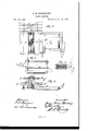
- Figure 1 of the said drawings represents a end of the finger-beam A is the divider B, I
- the fender B which directs the grain toward the inner end of the cutting apparatus.
- the collectingconveyer O which, in this instance, consists of an endless belt of canvas supported upon rollers, to one, a, of which a revolving motion is imparted, to cause the upper surface of the collecting -conveyer to carry the cut grain toward that side of the machine at which it is to be bound into sheaves.
- Motion may be imparted to the roller a by means of a chain or belt, and other gearing connecting it with the main running wheel; but as the construction of such transmitting mechanism or gearing is well known by manufacturers of binder-harvesters, I do not deem it necessary to either represent or describe it.
- the duplex elevator D At the delivery end of the collecting-conveyer is the duplex elevator D. This device consists of two endless belts, b b, of canvas, each of, which is supported upon two rollers,
- One of the belts, b has its lower roller 1 above the surface of the collecting-conveyor
- the combinations and arrangements of these J, so that the grain on the latter can pass under the end of that elevating-band to the face of the other, I).
- the end of the other band, b is close to the end of the collecting-conveyor, so that the grain delivered by the latter is within the range of the former.
- the upper or delivery ends of the two belts are at the same level, so that the grain which is raised is either centered at the diverging delivery OFFICE.
- Fig. 2 represents a ⁇ r ends of the belts, or, if permitted to accumulate, is distributed laterally in opposite directions by the outward movement of the belts over their supporting-rollers.
- the two belts are driven from the main driving-wheel by means of suitable transmitting mechanism or gearing, so that their adjacent faces move in the same upward direction and with equal speeds.
- the main driving-wheel is arranged to run between the cross-beams d d of the frame.
- the duplex elevator carries the grain upward by grasping it between its adjacent rising and moving faces, and discharges the grain at its upper end, where the divergence of the belts forms a species of mouth or receptacle, in which the grain, if not removed, accumulates in a gavel.
- a binders foot-board, E is arranged at each side of the upright elevator, one of these foot-boards E being at the outer side of the elevator, and the other foot-board being at the inner side of the elevator.
- This arrangement enables two or more binders to ride upon the machine in convenient positions to grasp the gavel at the upper end of the elevator and remove it therefrom without being in the way of each other, and without being obliged to expend, in the transfer of grain to separate binding-tables, time-that might otherwise be available for binding.
- a guard, M is attached to the machine at about the level ofthe binders table, to prevent the binder upon the inner platform from being accidentally thrown off, and also to prevent the conveyer beneath from being injured or obstructed by the fall of the binder upon it.
- binders tables In order that the grain may be conveniently bound, two binders tables, F F, are provided, one of them being at the outer side of the upright elevator, and the other table being at its inner side, so that the binder, standing upon either footboard E or E, may move the gavel toward him, and may bind it into a sheaf. .
- the binders may drop the sheaves on the ground; but as it is convenient to have them collected in shocks, I have combined with the binding appliances a dropping sheafcarrier, G.
- This implement is hinged to the rear ends of the binders" foot-boards, so that its rear can turn up or down; it is constructed, by preference, of slats, so that it is of light weight, and it is fitted with a cord, g, by means of which it may be drawn upward and held in a raised position, as seen in Fig. 3.
- the cord has a large knot made in it, which can be engaged with a fork, h, at the top of I the elevator-frame, so that the rope may be readily secured for the purpose of holding the carrier in a raised position, or may be readily loosed, for the purpose of permitting the carrier to tip down and discharge the sheaves with which it is loaded.
- the sheaves as bound are thrown upon the carrier, and when a number have accumulated on it one of the binders or the driver of the machine disengages the rope from the fork, drops the sheaves, draws up the carrier by the rope, and secures it by engaging the knot at the rope with the fork h.
- the mechanism thus described possesses several important advantages, thusz'
- the grain is collected in a gavel or bunch at as high a level or higher than the binding-tables; hence the binders do not have to raise the gavels in transferring them to the bindingtables, and they do not have to dig their hands down into a deep receptacle to seize the gavel, but merely to grasp the gavel and draw it sidewise.
- the elevator-bands are, by preference, made without projections, as the eflect of such projections would be to grind upon the grain accumulating at the upper end or mouth of the elevator, which would be prejudicial. Such projections also might injure the fingers of the binders when grasping the gavel.
- the leading feature of the machine is the duplex elevator, consisting of endless belts, whose adjacent surfaces move in the same direction with equal speed, or thereabout, and whose upper ends are at the same level, or thereabout.
- This duplex elevator is arranged, by preference, with its rising faces upright; but it may be inclined, if found expedient.
- this elevator is used in combination with binders tables or platforms at about the same level as its deliveryend, the diverging space between the upper ends of its members forms a receptacle, in which a gavel or bunch of grain collects by additions to its under side, thus obviating the necessity of a special grain-receptacle. As the grain is shoved up into the receptacle against that already therein, the gavel is more or less compacted and prepared for binding. Moreover,
- this receptacle is comparatively shallow and the gavel or bunch,when large enough to form a sheaf, projects upward from it, but little exertion is required on the part of a binder to grasp the gavel and draw it to a convenient position for binding.
- duplex elevator round leather belts may be substituted for bolt rope; or the canvas may be stitched to the faces of flat leather belts, and the rollers supporting the belt may have flat grooves in them adapted to such belts. There may also be strengthening-belts between those at the margins of the elevator-belts.
Landscapes
- Life Sciences & Earth Sciences (AREA)
- Environmental Sciences (AREA)
- Belt Conveyors (AREA)
Description
'G. H. SPAULDING.
HAND-BINDER.
No.185,459. Patented Dec.19, 1876.
MVQW.
THE GRAPHIC CO. NM
GEORGE-HENRY SPAULDING, OF ROCKFORD, ILLINOIS, ASSIGNOR OF ONE- HALF HIS RIGHT TO WM. A. KNOWLTON, OF SAME PLACE.
IMPROVEMENT IN HAND-BINDERS.
' Specification forming part of Letters Patent N 0. 185,459, dated December 19, 1876; application filed v May 13, 1876.
on a harvester without interfering with each.
others acts; also, to reduce the labor expended in taking the grain from the grainelevating mechanism. I
To this end my invention consists of certain combinations and arrangements of me-v chanical instrumentalities, of which the following are the principal, viz a duplex elevator, consisting of two endless belts, arranged with their acting faces parallel, or thereabout, to each other, and arranged to move with substantially equal speeds, and with.
their delivery ends at the same level, or thereabout; two binders tables or grain platforms, arranged at opposite sides of the opposite ends of the duplex elevator; two bind ers foot boards or supports, upon which the binders are supported while binding the grain; a tipping sheaf-table, upon which the sheaves are accumulated until it is deemed expedient to drop them on the field; a collecting-conveyer, by means of which the cut grain is collected and delivered to the elevator.
This conveyer may consist of a single belt,
either plain or fitted with cleats, or it may:
consist of a series of belts, either plain or fitted with teeth.
instrumentalities, which I claim as new, are set forth at the close of this specification.
In order that they may be fully understood I,have represented in the accompanying drawing, and will proceed to describe, the mode in which I have embodied them in a working machine. v
Figure 1 of the said drawings represents a end of the finger-beam A is the divider B, I
by means of which the grain to be cut is divided from that to be left standing, and at the inner end of the finger-beam is the fender B, which directs the grain toward the inner end of the cutting apparatus. Immediately behind the finger-beam A is the collectingconveyer O, which, in this instance, consists of an endless belt of canvas supported upon rollers, to one, a, of which a revolving motion is imparted, to cause the upper surface of the collecting -conveyer to carry the cut grain toward that side of the machine at which it is to be bound into sheaves.
Motion may be imparted to the roller a by means of a chain or belt, and other gearing connecting it with the main running wheel; but as the construction of such transmitting mechanism or gearing is well known by manufacturers of binder-harvesters, I do not deem it necessary to either represent or describe it. At the delivery end of the collecting-conveyer is the duplex elevator D. This device consists of two endless belts, b b, of canvas, each of, which is supported upon two rollers,
. e e e c, which are so arranged in the machine that the adjacent faces of the two aprons are upright and parallel with each other, or nearly so. One of the belts, b, has its lower roller 1 above the surface of the collecting-conveyor The combinations and arrangements of these (J, so that the grain on the latter can pass under the end of that elevating-band to the face of the other, I). The end of the other band, b, is close to the end of the collecting-conveyor, so that the grain delivered by the latter is within the range of the former. The upper or delivery ends of the two belts are at the same level, so that the grain which is raised is either centered at the diverging delivery OFFICE.
Fig. 2 represents a \r ends of the belts, or, if permitted to accumulate, is distributed laterally in opposite directions by the outward movement of the belts over their supporting-rollers. The two belts are driven from the main driving-wheel by means of suitable transmitting mechanism or gearing, so that their adjacent faces move in the same upward direction and with equal speeds. The main driving-wheel is arranged to run between the cross-beams d d of the frame. As the construction of such transmitting' mechanism or gearing is well understood by constructers of harvesters, it is not deemed necessary to represent it. In order that the belts may be kept in their proper positions, a bolt rope is sewed into each edge of each belt, and a corresponding groove is made in each belt-roller to receive the inner half, or thereabout, of each of these roped edges. (See Fig. 4.)
The duplex elevator carries the grain upward by grasping it between its adjacent rising and moving faces, and discharges the grain at its upper end, where the divergence of the belts forms a species of mouth or receptacle, in which the grain, if not removed, accumulates in a gavel. In order that the grain may be readily removed and bound by two binders, a binders foot-board, E, is arranged at each side of the upright elevator, one of these foot-boards E being at the outer side of the elevator, and the other foot-board being at the inner side of the elevator. This arrangement enables two or more binders to ride upon the machine in convenient positions to grasp the gavel at the upper end of the elevator and remove it therefrom without being in the way of each other, and without being obliged to expend, in the transfer of grain to separate binding-tables, time-that might otherwise be available for binding. A guard, M, is attached to the machine at about the level ofthe binders table, to prevent the binder upon the inner platform from being accidentally thrown off, and also to prevent the conveyer beneath from being injured or obstructed by the fall of the binder upon it.
In order that the grain may be conveniently bound, two binders tables, F F, are provided, one of them being at the outer side of the upright elevator, and the other table being at its inner side, so that the binder, standing upon either footboard E or E, may move the gavel toward him, and may bind it into a sheaf. .The binders may drop the sheaves on the ground; but as it is convenient to have them collected in shocks, I have combined with the binding appliances a dropping sheafcarrier, G. This implement is hinged to the rear ends of the binders" foot-boards, so that its rear can turn up or down; it is constructed, by preference, of slats, so that it is of light weight, and it is fitted with a cord, g, by means of which it may be drawn upward and held in a raised position, as seen in Fig. 3.
, The cord has a large knot made in it, which can be engaged with a fork, h, at the top of I the elevator-frame, so that the rope may be readily secured for the purpose of holding the carrier in a raised position, or may be readily loosed, for the purpose of permitting the carrier to tip down and discharge the sheaves with which it is loaded. The sheaves as bound are thrown upon the carrier, and when a number have accumulated on it one of the binders or the driver of the machine disengages the rope from the fork, drops the sheaves, draws up the carrier by the rope, and secures it by engaging the knot at the rope with the fork h.
The mechanism thus described possesses several important advantages, thusz' The grain is collected in a gavel or bunch at as high a level or higher than the binding-tables; hence the binders do not have to raise the gavels in transferring them to the bindingtables, and they do not have to dig their hands down into a deep receptacle to seize the gavel, but merely to grasp the gavel and draw it sidewise. The elevator-bands are, by preference, made without projections, as the eflect of such projections would be to grind upon the grain accumulating at the upper end or mouth of the elevator, which would be prejudicial. Such projections also might injure the fingers of the binders when grasping the gavel.
It will be noticed that the leading feature of the machine is the duplex elevator, consisting of endless belts, whose adjacent surfaces move in the same direction with equal speed, or thereabout, and whose upper ends are at the same level, or thereabout. This duplex elevator is arranged, by preference, with its rising faces upright; but it may be inclined, if found expedient. When this elevator is used in combination with binders tables or platforms at about the same level as its deliveryend, the diverging space between the upper ends of its members forms a receptacle, in which a gavel or bunch of grain collects by additions to its under side, thus obviating the necessity of a special grain-receptacle. As the grain is shoved up into the receptacle against that already therein, the gavel is more or less compacted and prepared for binding. Moreover,
as this receptacle is comparatively shallow and the gavel or bunch,when large enough to form a sheaf, projects upward from it, but little exertion is required on the part of a binder to grasp the gavel and draw it to a convenient position for binding.
In the construction of the duplex elevator round leather belts may be substituted for bolt rope; or the canvas may be stitched to the faces of flat leather belts, and the rollers supporting the belt may have flat grooves in them adapted to such belts. There mayalso be strengthening-belts between those at the margins of the elevator-belts.
Where the binders tables are mentioned in any of the claims, the term is to be considered as having a general meaning as regards the plane of the tables with reference to the top of the elevator.
I claim as my invention 1. The combination, substantially as before set forth, of the collecting-conveyer and the duplex elevator, constructed with the delivery ends of its members at the same level.
2. The combination, substantially as before set forth, of the duplex elevator, constructed with the delivery ends of its members at the same level, the binders tables, arranged at opposite sides of the upper end of the duplex elevator, and the binders supports,
arranged at opposite sides of the duplex el'e-
Publications (1)
| Publication Number | Publication Date |
|---|---|
| US185459A true US185459A (en) | 1876-12-19 |
Family
ID=2254865
Family Applications (1)
| Application Number | Title | Priority Date | Filing Date |
|---|---|---|---|
| US185459D Expired - Lifetime US185459A (en) | Improvement in hand-binders |
Country Status (1)
| Country | Link |
|---|---|
| US (1) | US185459A (en) |
-
0
- US US185459D patent/US185459A/en not_active Expired - Lifetime
Similar Documents
| Publication | Publication Date | Title |
|---|---|---|
| US185459A (en) | Improvement in hand-binders | |
| CN104394682B (en) | United reaper | |
| US1333493A (en) | Potato-harvester | |
| US3521438A (en) | Strawberry harvester | |
| US2313670A (en) | Pickup attachment for harvesting implements | |
| US1485532A (en) | Combination harvester | |
| US185873A (en) | Improvement in harvesters | |
| US190702A (en) | Improvement in hand-binders | |
| US347316A (en) | Cane and corn harvester | |
| USRE9537E (en) | Harvester | |
| US226985A (en) | Hay and grain elevator | |
| US2524077A (en) | Pea harvester and loading machine | |
| USRE8703E (en) | Improvement in harvesters | |
| US1324017A (en) | Sheaf-gatherer | |
| US693505A (en) | Threshing-machine. | |
| US167387A (en) | Improvement in harvesters | |
| US2967389A (en) | Cutting and windrowing apparatus | |
| US175157A (en) | Improvement in harvesters | |
| US222772A (en) | Improvement in combined reaper, thrasher, and separator | |
| US425139A (en) | mercer | |
| US201563A (en) | Improvement in harvesters | |
| US728906A (en) | Flax attachment for harvesting-machines. | |
| US290459A (en) | Grain-binding harvester | |
| US1328791A (en) | Corn-harvester | |
| US139900A (en) | Improvement in harvesters |