US1854590A - Machine for use in the manufacture of shoes - Google Patents
Machine for use in the manufacture of shoes Download PDFInfo
- Publication number
- US1854590A US1854590A US497237A US49723730A US1854590A US 1854590 A US1854590 A US 1854590A US 497237 A US497237 A US 497237A US 49723730 A US49723730 A US 49723730A US 1854590 A US1854590 A US 1854590A
- Authority
- US
- United States
- Prior art keywords
- jack
- shoe
- lever
- last
- machine
- Prior art date
- Legal status (The legal status is an assumption and is not a legal conclusion. Google has not performed a legal analysis and makes no representation as to the accuracy of the status listed.)
- Expired - Lifetime
Links
- 238000004519 manufacturing process Methods 0.000 title description 26
- 230000008093 supporting effect Effects 0.000 description 33
- 230000007246 mechanism Effects 0.000 description 22
- 230000002045 lasting effect Effects 0.000 description 13
- 239000011435 rock Substances 0.000 description 13
- 241000282472 Canis lupus familiaris Species 0.000 description 7
- 210000003414 extremity Anatomy 0.000 description 6
- 230000000994 depressogenic effect Effects 0.000 description 5
- 238000010276 construction Methods 0.000 description 4
- 241000719193 Seriola rivoliana Species 0.000 description 2
- 210000000481 breast Anatomy 0.000 description 2
- 238000006073 displacement reaction Methods 0.000 description 2
- 241000239290 Araneae Species 0.000 description 1
- 101150000595 CLMP gene Proteins 0.000 description 1
- 241000276694 Carangidae Species 0.000 description 1
- 101100382322 Drosophila melanogaster Acam gene Proteins 0.000 description 1
- 208000007101 Muscle Cramp Diseases 0.000 description 1
- 230000000694 effects Effects 0.000 description 1
- 238000003780 insertion Methods 0.000 description 1
- 230000037431 insertion Effects 0.000 description 1
- 210000001364 upper extremity Anatomy 0.000 description 1
- 230000037303 wrinkles Effects 0.000 description 1
Images

Classifications
-
- A—HUMAN NECESSITIES
- A43—FOOTWEAR
- A43D—MACHINES, TOOLS, EQUIPMENT OR METHODS FOR MANUFACTURING OR REPAIRING FOOTWEAR
- A43D23/00—Single parts for pulling-over or lasting machines
- A43D23/02—Wipers; Sole-pressers; Last-supports; Pincers
- A43D23/025—Last-supports
Definitions
- the present invention relates to machines for use in the manufacture of shoes, and more particularly to an improved jack, jack supporting structure and mechanism for actuating and controlling a jack in a machine of the type in which the shoe and the means for operating on the shoe are moved relatively to transfer the point of operation along the shoe, and in which the relative positions of the shoe and the operating means are changed, as the point of operation is transferred along the shoe, to present the shoe properly to the operating means.
- the invention is herein disclosed as embodied in an automa tic side lastin machine of the same general description as the machines disclosed in the inventors pending application Serial No. 295,080 filed July 24:, 19:28, of which the present application is a division, and in the patent to the present inventor No. 1,706,619 dated March 26, 1929.
- This machine is provided with a jack arranged to receive a last upon which are assembled a shoe upper and an insole and with a pair of lasting units provided with upper grippers and wipers for tensioning the shoe upper and working it into lasted relation to the last and insole, and with means for securing the upper in that relation.
- the machine is provided with automatic controlling means arranged, when once the machine is started, to cause it to operate through a predetermined number of cycles and then to come to rest. Means are also provided for controlling the relative feeding movement of the lasting units and the jack in accordance with the size of the shoe in the jack so that the length of the steps of the feeding movement, which takes place between the successive operations of the lasting units, is varied in accordance with the size of the shoe, whereby the necessity of varying the number of these steps in operating upon shoes of different sizes is avoided.
- the jack be constructed in such a mannor as to permit tipping or rocking movements of the shoe about axes extending lengthwise and transversely of the shoe to bring the shoe into the proper position to enable the devices which act upon the shoe to operate to the best advantage, and it is also desirable that the jack be so arranged as to permit a lengthwise feeding movement of the shoe with relation to the operating devices to transfer the point of operation along the shoe.
- the principal object of the present invention is to provide a novel and improved jack and jack supporting and actuating structure particularly adapted for use in machines of the type referred to.
- Other objects of the invention are to provide novel and improved constructions and arrangements of parts which are also capable of use in the shoe supporting jacks and jack actuating and controlling mechanisms of other types of automatic shoe machines or shoe machines which are not automatic either in whole or in part.
- the jack of the machine herein illustrated and described as embodying the several features of the present invention is provided with a last pin and toe rest mounted to rock about an axis extending lengthwise of a last in the ack, and this last pin and toe rest are also arranged so as to have a relative movement towards and from each other in order to position a shoe properly upon the jack and clamp it firmly in place.
- a feature of the invention contemplates the provision of connections such, for instance, as a link between the last pin and the toe rest arranged to permit the last pin and toe rest to rock about an axis extending lengthwise of a last in the jack, and to cause the angular relation of the last pin to the toe rest to remain unchanged during said rocking movement.
- another feature of the invention contemplates locating the axis about which the last pin and the toe rest can rock (assuming the lastto be positioned sole upwardly) above the bottom face of the last at the shank thereof, the last being positioned with its bottom facing upwardly.
- the position ing of the ball portion of the insole somewhat above this axis does not render the last objectionably instable. and the illustrated construction is so arranged.
- the illustrated connections between the last pin and the toe rest are arranged when the machine is at rest to hold the toe rest and last pin spaced further apart than they ever will normally be during the operation of the machine, said mechanism in cluding also means operated by a plunger passing through the last pin arranged as a last is applied to the jack to condition the connections in such a manner as to permit aspring to move the last pin toward the toe rest to a position determined by the length of the last which has been applied to the jack.
- Another feature of the present invention contemplates the provision of improved jack supporting means to control the presentation of the jack and a work piece carried thereby to the operating instrumentalities of the machine.
- the ack of the illustrated machine is supported by a lever mounted for universal movement and supported by a second, spring-pressed lever, means being provided for varying the tension of the spring to vary the force with which the shoe in the jack is pressed against an abutment carried by the machine as may be necessary or desirable during the performance of the operation.
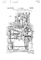
- Fig. 1 is a front elevation of a side lasting and fastening machine embodying the invention, various portions of the box-like frame or base of the machine being broken away more clearly to disclose the moving parts of the machine;
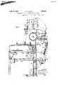
- Fig. 2 is a side elevation of the machine of Fig. 1 looking from the left, the boxlike base being shown in cross section;
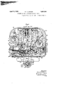
- Fig. 3 is a horizontal section taken below the head of the machine and with the top portion of the base largely broken away to show the mechanism therebelow
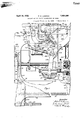
- Fig. 1 is a front elevation on a larger scale than Fig. 1, showing parwhich it occupies during the operation of the machine and showing more of the supporting means for the jack.
- the illustrated side lasting machine is provided with a box-like base or frame 50, bestshown in Figs. 1, 2, and 3, carrying a head 52 which supports, at the front of the machine, a pair of lasting units 5%, 56, each provided with means for working a shoe upper into lasted relation to a last and insole, and with means for forming staples and inserting them through the shoe upper into the insole to secure the shoe upper in lasted relation to the last and insole.
- These mechanisms are for convenience spoken of in this specification as upper-tensioning and stapling units. Beneath these upper-tensioning and stapling units is a ack 58 carried at the forward extremity of an arm 60. The rear end of the arm 60 is supported by a bracket 62 (Fig.
- the arm 60 is supported near its forward extremity by a bell crank lever 64: fulcrumed at 66 to the frame 50 and having a substantially horizontally extending arm 68 carrying a roll 70 hearing against the lower surface of the arm 60 (see Figs. 1 and 5).
- the bell crank lever 64 also has a substantially vertically extending arm 72 to the lower end of which is secured one end of a long coil spring H the other end of which is secured to a downwardly extending arm 7 6 of another bell crank lever 78 also fulcrumed to the base 50 and having a substantially horizontally extending arm 80 connected by a link 82 to a lever 84 (Figs. 1 and 2) fulcrumed at 86 to the base 50.
- the lever 84 carries a cam roll 88 bearing against a cam 90 fast upon a transversely extending cam shaft 92 which is rotated by mechanism hereinafter described once during the operation of the machine upon each shoe.
- the machine is provided with means for moving the ack 58 toward the left as viewed in Fig. 1 to present different parts of the shoe to be operated on successively to the uppertensioning and stapling units 54, 56.
- the configuration of the cam 90 is such as to rock the bell crank lever 6 1 in a clockwise direction as viewed in Fig. 1 to hold a shoe 94: mounted upon a last 96 (Fig. 5) carried by the jack 58 in its uppermost position with its insole 98 pressed against a pair of presser feet 100, 102 (Fig.
- the lasted shoe is supported in the jack 58 by means of heel and toe supports which are pivotally mounted so as to permit the supports with the lasted shoe thereon to swing or rock about an axis extending lengthwise or longitudinally of the shoe.
- the presser-feet 100, 102 engage the surface of the insole near its margin and thus resists the upward pressure ateach side of a vertical plane passing through the pivotal axis of the heel and toe supports.
- the upward pressure of the shoe against the presser-feet 100, 102 therefore acts to rock the shoe transversely so as to keep the surface of the sole against both of the presserfeet and maintain the sole transversely of the shoe in the proper plane with relation to the upper tensioning and stapling units.
- a jack 58 is provided to carry the last 96 on which is assembled the shoe upper 94 and the insole 98 which are to be operated upon.
- the jack 58 is connected to the forward end of the arm 60 by a gimhal joint.
- the arm 60 is provided with a circular groove. the upper surface of which is formed by an annular plate 652.
- the flange of a ring 654 is secured by a gimbal joint of usual construction so that the jack 58 can have universal rocking movement to a limited extent.
- An arm 658 is secured to the ring 654 and is pivotally connected to a rearwardly extending link 660, the rear end of which is connected to an arm 662 rigid with the bracket 62 so that the movement of the longitudinal axis of the. shoe. as the jack is moved, will be parallel and there will be no turning off of the shoe about a vertical axis.
- the jack 58 has an upper approximately U- shaped portion having two arms 664, 666 connected by an aproximately horizontal portion 670 from which a hollow spindle 672 extends downwardly to the base 656.
- a shaft 674 Housed within the spindle 672, and having appropriate bearings therein, is a shaft 674 having a bevel gear 676 fast upon its upper end.
- the shaft 674 is connected by a universal joint to a dish-shaped pulley 680 mounted for rotary movement, on a short, vertical shaft 684 carried at the center of a spider 686 secured to the outer end of the arm 60.
- the pulley 680 is provided with a groove 688 about which passes a cable 690 which extends rearwardly through the arm 60, as shown in dotted lines in Fig. 3.
- One end of the cable 690 passes about a small pulley 692 carried by the arm 60 and then to the right about a larger pulley 694 to which the end of the cable is secured.
- the pulley 694 is rigidly secured to a spur gear 696, the two being mounted upon a short shaft 698 carried by the base 50 near the front, right-hand corner of the machine, as shown txaminer in Figs. 1 and 3.
- the gear 696 meshes with a pinion 700 fast upon the lower end of the shaft 354 (Figs. 4 and 5).
- the other end of the cable 690 also extends rearwardly through the arm 60, crossing the end which has already been described, and passes about a small pulley 702 carried by the arm 60. From the pulley 702 the cable 690 passes rearwardly and to the left and then downwardly about a pulley 704 (Figs 1 and 3) and beneath a pulley 706 secured to a weight 708. From the pulley 706 the cable 690 passes upwardly and is connected to the end of a chain 710 which continues upwardly and about a pulley 712 carried by the frame 50, then horizontally forward, about a pulley 714 carried by a bracket 716 secured to the base 50.
- the weight 708 will rotate the shaft 674 in a counter-clockwise direction when permitted so to do by the disconnection of the pulley 694 from the gear 696 which is accomplished by the means illustrated and described in Patent No. 1,706,619 hereinbefore referred to.
- the upper end 664 of the U-shaped portion of the jack 58 is provided with a horizontal, transversely extending sleeve 730 forming a guideway for a rack bar 732 to the forward end of which is secured. for rocking movement about the axis of the rack bar 732, the longer arm of an approximately U-shaped member 7 34.
- the shorter. upwardly extending arm 736 of the member 734 is reduced at its upper extremity to form a last pin 738.
- the upwardly extending arm 736 of the memher 734 iscOunterbored to receive a plunger 740 pressed upwardly by a spring 742 housed in a hollow portion of the plunger and hearing at its lower end against a pin 744 carried by the member 734 and extending through a slot in the wall of the plunger.
- a toe rest 746 Pivoted to the upper end of the arm 666 of the jack 58, for horizontal movement about a transverse axis, is a toe rest 746, the toe rest 746 being connected with the member 734 by two angularly related links 748, 750 so that the member 734 and the last pin 738 may move toward and from the toe rest 746 but the toe rest 746 and the last pin 738 are at all times maintained in alinement with each other and their angular relation to each other cannot change.
- Fulcrumed at 752 to the approximately horizontal portion 670 of the jack 58 is a lever 7 54 extending upwardly and connected by a toggle 756 with a lever 758 fulcrumed at 7 to the portion 670 of the jack
- Another lever 762 is also fulcrumed at 760, extending in the opposite direction from the lever 758 and having at its lower end a bevel gear sector 76st meshing with the bevel gear 676 at the upper end of the shaft 674.
- a spring 766 connects the two levers 758 and 762 while an adjustable stop screw 768 limits the movementof the two levers under the action of the spring.
- the levers 758 and 762 normally act as a single lever, the spring 766 serving as a safety device.
- a link 770 is connected at one end to the lever '75l approximately half way between its fulcrum 752 and the toggle 756 and is connected at the other end to the lower arm of a lever 7 72 fulcrumed at 77% to the jack 58 and urged in a counterclockwise direction, as viewed in Fig. 4, by a tension spring 776 anchored at one end to the lever 772 and at the other end to the spindle 672 of the jack 58.
- the lever 772 is formed with a gear segment 778 meshing with a gear segment 780 formed at the lower end of a lever 782 fulcrumed at 784 some what above the median portion of the arm 664 of the jack 58.
- the lever 782 At its upper end the lever 782 is provided with another gear segment meshing with the rack of the rack bar 732.
- the spring 776 tends to urge the rack bar 732 and the last pin 738 toward the toe rest 746, but this movement is resisted when the machine is at rest by the toggle 756 which at that time is in a. straightened condition and must be broken before the last pin 738 can move toward the toe rest 7 46.
- a spring 792 connected at one end to the horizontally extending arm of the bell crank lever 786 and at the other end to the horizontal portion 670 of the jack 58, tends to lift the horizontally extending arm of the bell crank 786 and at the same time to rock that lever in a clockwise direction, as viewed in Fig. i, into engagement with a stop pin 79% carried by the jack 58.
- a second pin 796 serves to limit the upward movement of the link 788 under the influence of the spring 792.
- a lever 798 Fulcrumed near the forward extremity of the link 770 is a lever 798, one end of which is turned upwardly at 800 to bear against the lower surface of the table 785 and the othersend of which is turned upwardly at 801 beneath the toggle 756.
- the plunger 740 is forced downwardly by the placing of a last in the jack 58, the bell crank lever 786 is depressed bodily, rocking the lever 798 in a counter-clockwise direction, as viewed in Fig. 4. and causing the right-hand end of the lever 798 to move upwardly engaging and breaking the toggle 756.
- the toggle 756 is in a straightened condition and, thereafter as the jack is returned to its initial position, the shaft 674 is rotated in the reverse direction. thereby separating the heel support from the toe support and releasing or unjacking the shoe.
- the operation of the shaft 674:, levers 758 and 762, and toggle 756 is substantially the same as the corresponding parts of the machine of applicants prior patent.
- the heel support is forced away from the toe support to unclamp the shoe at the conclusion of the operation on the shoe, the shoe, of course, is still in position on the jack and the toggle breaking plunger 740 is still held in its depressed position.
- the lower end of the plunger is therefore below the upper end of the lever 786 and as the heel support is pushed away from the toe support the plunger 740 swings the lever 7 86 rearwardly but does not move to a position in which the lever can move beneath the plunger.
- the toggle mechanism of the jack cannot be tripped until after the shoe is removed from the ack and the plungcr is allowed to rise, thereby permitting the lever 786 with its plate 785 to be again positioned directly beneath the plunger.
- Means which will now be described. is provided for moving the jack 58 to the left, transversely of the machine. to present a shoe upon a. last carried by the jack to the upper-tensioning and stapling instrumentalities of the units 54, 56.
- the upper end of the forward arm 666 of the jack 58 is connected by a link 810 to the forward end of the feed lever 726.
- the median portion of the lever 726 is connected by links 812 and 814 to the rearwardly extending end of a large horizontal bell crank lever 816 fulcrumed at 818 near the top of the base 50 of the machine.
- the forward arm of the bell crank lever 816 carries a cam roll 820 bearing against a cam 822 at the upper end of the bank of cams 642 and held in engagement with the cam 822 by the weight 708.
- the cam 822 is of such a configuration that as it rotates the lever 726 moves step-by-step from right to left. in a clockwise direction as viewed in Fig. 3, thereby feeding the jack step-by-step to the left. the upper tensioning and stapling mechanism of the units 54, 56 operating upon the sh e during the pauses between the successive steps of feeding movement.
- the cam 822 may be made of such a configuration as to cause a short feeding step after the grippers 136 have seized and tensioned the upper but before the first staple is inserted. Except for this first cycle of operation of the upper-teusioning and stapling mechanism, the machine operates to cause the grippers 136 to grip and tension the shoe upper and then to insert a staple through the shoe upper and into the rib of the insole without intervening feeding movement.
- pantograph mechanism is provided, controlled by the size of the shoe placed in the jack 58.
- pantograph mechanism which is of the same type as that disclosed in applicants prior Patent No.
- the lever 754 of the jack 58 carries at its upper end a ball 824 arranged to engage against a surface 826 to which it is led by a pair of converging ribs 828 formed on a plate 830 at the end of a rod 882 mounted for forward and rearward sliding movement in guides carried by or formed in the top of the base 50 of the machine.
- the operator takes hold of the jack and swings it rearwardly. bringing the ball 824 into position between the ribs 828 and then permitting it to rise under the influence of the spring 74 into engagement with the surface 826.
- the position of the jack transversely of the machine is controlled in accordance with the size of the shoe.
- the connection between the jack 58 and the 726 at the time the machine is started will depend upon the size of the shoe in the jack and the larger the shoe the further the forward end of the lever 726 will be swung to theright.
- the extreme rearward end of the fulcrum lever 722 is pivoted to a rod 838 mounted for sliding movement in a sleeve 840 fulcrumed' at 842 to the rear of the base 50 and carrying a pair of pivoted dogs 844 arranged, when swung in one direction, to clamp the rod 838 in the sleeve 840 and, when swung in the other direction, to release the rod 838 for sliding movement in the sleeve 840.
- the dogs 844 are normally held in position to clamp the rod 838 to the sleeve 840 but are moved to releasing position for an instant as the machine is started so as to permit the relation of the rod 888 to the sleeve 840 and consequently the posi tion of the fulcrum lever 722 and the position of the link 834 to be varied according to the length of the shoe in the jack.
- the forward ends of the dogs 844 are provided with pins 846 engaged in slots formed in the ends of a bar 848 pivoted to a forwardly extending sleeve 850 in which is housed a spring 852 bearing at its forward end against an internal shoulder formed at the end of the sleeve 850 and at its rearward end against a shoulder formed on a rod 854 which passes through the spring 852 and the sleeve 850 and is pivoted at its forward end to the right-hand end of a horizontal swinging lever 856 fulcrumed beneath the top of the base 50 and connected intermediate its ends by a link 8558 with the left-hand end of a lever 860 also fulcrumed beneath the top of the base 50.
- the lever 860 is held latched in the position shown in Fig. 3 by a spring-held latch 862 which engages a lug 864 formed on the lever 860.
- the jack 58 is moved into operative position preparatory to the starting of the machine, the latch 862 is swung in a counterclockwise direction, as viewed in Fig. 3, by mechanism hereinafter described, thus releasing the lever 860 and permitting the rod 854 to move rearwardly thereby releasing the tension of the spring 852.
- the treadle 87 0 in the machine is shown in Figs. 1, 2 and 3. It is fulcrumed at 872 and is normally urged in an upward direction by a spring 874 anchored at one end to the treadle and at the other end to the base 50.
- the treadle 87 0 is connected through a vertical rod 876 with a bell crank lever 87 8 at the upper left-hand front corner of the base 50.
- the bell crank lever 878 is connected by a link 880 with the left-hand end of a slidably mounted rod 882 ( Figures 1 and 3) extending transversely of the machine and provided with an upstanding pin. 884 (Fig.
- the spindle 67 2 of the jack is connected by a universal joint 888 with a rearwardly extending rod 890 to which is secured the front end of a tension spring 892 which is anchored to the rear of the base 50 of the machine.
- a tension spring 892 which is anchored to the rear of the base 50 of the machine.
- the rod 890 is pivoted to the free end of a link 894 (Fig. 2) pivoted at its lower end to the bracket 62 for vertical swinging movement.
- a nut and lock nut 896 threaded upon a rod 898 which is anchored at its rear end to the base 50 and passes through a hole in the upper end of the link 894;
- a screw and slot connection to the median portion of the rod 890 is a plate 900 having near its forward end an upwardly extending rearwardly curved finger 902 arranged, when the machine is at rest, to be hooked about a longitudinally slotted lever 904 pivoted to the lower end of a spring-held lever 906 fulcrumed for vertical swinging movement about a short horizontal shaft 908 near the top of the base 50.
- a spring 910 coiled about the shaft 908 and anchored at one end to the shaft and at the other end to the base 50 of the machine, tends to rotate the lever 906 in a clockwise direction, as viewed in Fig. 2, on the shaft 908, the lever 906, however, being rocked to a depending position, by motion transmitted through a gear sector 912 fast upon the shaft 908 and provided with a pin 913 arranged, as the gear sector 912 moves in a downward and forward direction, to engage the lever 906 and force it in a counterclockwise direction as viewed in Fig. 2 into depending position where it is held by the engagement of a latch 916 on the lever 906 with a corresponding abutment on the machine frame.
- This mechanism is more fully set forth in applicants patent above referred to.
- the illustrated machine is provided with means for tilting the jack 58 transversely of the machine and longitudinally of the shoe in the jack to maintain the portion of the insole of the shoe, adjacent to which the lasting is being performed, at all times in a horizontal plane so that the gripper aws 136 will pull the upper stock in a direction heightwise of the last and substantially normal to the insole and so that the staples will be inserted through the upper and into the rib of the insole with their bars parallel to the surface of the insole.
- the arm 60 is pivoted toward its forward end to a link 982 the other end of which is pivoted to a lever 984 (Figs.
- a jack having a jack frame, a jack supporting member with which the frame has a pivotal connection at its lower end, and a last support pivotally mounted in the upper end of the frame having its pivotal axis extending lengthwise of and in close proximity to the bottom of the last.
- a jack having a ack frame, a last support pivotally mounted therein to rock about an axis extending lengthwise of the last, and a supporting member to which the frame is pivotally connected at its lower end for pivotal movement both transversely and lengthwise of the last.
- a jack having a jack frame, a last support pivotally mounted therein to rock about an axis extending lengthwise of the last, and a supporting member to which the frame is pivotally connected at its lower end for pivotal movement lengthwise of the last, said supporting member being mounted to permit translatory movement of said pivotal connection lengthwise of the last.
- a jack having a jack frame, a last support pivotally mounted therein to rock about an axis extending lengthwise of the last, and a supporting member to which the frame is pivotally connected at its lower end for pivotal movement both transversely and lengthwise of the last, said supporting member being mounted to permit translatory movement of said pivotal connection of the last.
- a jack having heel and toe supports, a frame on which the supports are pivotally mounted to permit a rocking movement of the shoe with relation to the frame on an axis extending length 'ise of the shoe, and a jack supporting member with which the frame has a pivotal connection at its lower end, said supporting member being movable to effect a tipping movement of the shoe about an axis extending transversely of the shoe, substantially in the plane of the shoe sole supported on the jack.
- a jack having heel and toe supports a frame on which the supports are pivotally mounted to permit a rocking movement of the shoe with relation to the frame on an axis extending lengthwise of the shoe, andmeans acting automatically upon placing a shoe in the jack to move the supports relatively to clamp the shoe in position.
- a machine for use in the manufacture of shoes having, in combination, a jack having a heel and toe supports, a frame on which the supports are mounted to permit a rocking movement of the shoe with relation to the frame on an axis extending lengthwise of the shoe, and means rendered active upon placing a shoe in the jack to actuate said supports to clamp the shoe firmly in position and at the end of the operation on the shoe automatically to release the shoe.
- a machine for use in the manufacture of shoes having, in combination, a shoe supporting jack comprising a frame, a last pin and toe support on the frame pivotally mounted to rock on an axis extending lengthwise of the shoe, means for performing an operation on the shoe supported on the jack,
- a machine for use in the manufacture of shoes having, in combination, a jack comprising aframe. a last pin and a toe rest mounted on the frame for rocking movement about an axis extending lengthwise of the last carried by the jack. means for relatively moving the toe rest and the last pin to clamp and unclamp a lasted shoe in the j ack, means for actuating the jack to move the point of operation along the shoe, a gage member on the machine, and a gage pin cooperating therewith connected to move in spaced relationship to the last pin to bring the shoe always to the same starting position irrespective of its size.
- a machine for use in the manufacture of shoes having, in combination, a jack comprising a frame, alastpin andatoe restmounted on the frame for rocking movement about an axis extending lengthwise of the last carried by the jack, means for relatively moving the toe rest and the last pin on the frame to clamp and unclamp a lasted shoe in the jack, means for actuating the jack to move the point of operation along the shoe, a gage pin movably mounted on the frame, and connections for controlling the position of the gage pin with relation to the last pin and toe rest in accordance with the length of shoe clamped on the jack.
- a machine for use in the manufacture of shoes having, in combination, a jack comprising a frame, a last pin and a toe rest mounted on the frame for rocking movement about an axis extending lengthwise of the last carried by the jack, connections for moving the last pin on the frame with relation to the toe rest to clamp and unclamp a lasted shoe in the ack, a gage pin movably mounted on the frame, connections between the last pin and the gage pin to position the gage pin ith relation to the last pin in the jack in accordance with the size of shoe clamped on the jack, and a gage member cooperating with the gage pin to position the shoe in the machine.
- a machine for use in the manufacture of shoes having, in combination. means for operating on a shoe, a jack comprising a frame, heel and toe supports relatively movable on the frame to clamp and unclamp a lasted shoe on the aclt, a gage device mounted on the frame, connections between the gage device and one of said supports for moving the gage device with relation to said support and frame in accordance with the size of the shoe clamped on the jack, and a gage device cooperating with said first mentioned gage device for positioning the jack in the machine-with relation to the means for operating upon the shoe.
- a machine for use in the manufacture of shoes having, in combination, devices for performing an operation progressively along the bottom margin of a shoe, a shoe supporting jack comprising a frame, a toe support on the frame, a heel support mounted on the frame so as to be movable towards and from the toe support, a gage device on the frame, connections between the heel support and gage device for moving said device with relation to the heel support and frame in accordance with the size of shoe clamped on the ack, and a gage device cooperating with said first mentioned gage device for positioning the jack with relation to the devices for operating upon the shoe.
- a machine for use in the manufacture of shoes having a shoe supporting jack comprising a frame, a last pivotally mounted in the frame to permit a rocking movement of the shoe on an axis extending lengthwise of the shoe, abutments arranged to engage near its marginal portions the sole of a lasted shoe supported upon the jack, means acting on the jack to force the shoe against said abutments, a jack supporting member with which the jack frame has a pivotal connection at its lower end, and means for moving said jack supporting member to tip the shoe about an axis joining said abutments and extending transversely across the shoe.
- a machine for use in the manufacture of shoes having, in combination, means for operating on a shoe, a jack comprising a frame, a movable member provided with a last pin mounted on the frame, a gage device, connections between said member and gage device for moving the gage device relatively to the frame in accordance with the size of the shoe placed in the jack and a gage device cooperating with said first mentioned gage device to determine the position of the jack with relation to the means for operating on the shoe.
- a jack having a pair of upwardly ex tending arms, a last pin carried by one arm and a toe rest carried by the other arm ar ranged for rocking movement relatively to said arms about an axis extending lengthwise of the sole of a last carried by said jack, means for moving the last pin and toe rest toward each other and for locking them in a position determined automatically by the dimensions of a last carried by the jack, and connections between the toe rest and the last pin arranged to maintain constant the relation of the last pin and the toe rest during the rocking movement thereof.
- a jack having a last pin and a toe rest mounted for rocking movement about an axis extending lengthwise of the sole of a last carried by the jack, and link connections between the toe rest and the last pin arranged to permit relative movement of the last pin and the toe rest toward and from each other but to prevent relative swinging movement of the last pin and the toe rest.
- a jack having a last pin and a toe rest mounted for rocking movement about an axis extending lengthwise of a last carried by the jack ind positioned substantially above the last bottom at the shank and toe portions of the last but somewhat below the last bottom at the ball portion of the last.
- a jack having a last pin and a toe rest mounted for swinging movement about an axis extending lengthwise of a last carried by the jack and positioned somewhat below the bottom of the last at the ball portion thereof and above the bottom of the last at the shank portion thereof.
- a jack comprising a frame, a pair of supports carried by said frame and mounted for rocking movement about axes arranged in alinement with each other, a toe rest carried by one of the supports, a last pin carried by the other support, and connections between the two supports arranged to maintain the angular relation of the last pin and the toe rest constant during said rocking movement.
- a jack comprising a frame, a pair of supports carried by the frame and mounted for rocking movement about axes arranged in alinement with'each other, means for causing relative movement of the supports toward and from each other, a toe rest carried by one of the supports, a last pin carried by the other support, and connections between the two supports arranged to maintain the angular relation of the last pin and the toe rest constant during said rocking movement.
- a jack comprising a frame, a last pin and a toe rest carried by the frame and ar ranged for rocking movement about axes in alinement with each other, gearing operable to move the last pin toward and from the toe rest, and link mechanism connecting the last pin and the toe rest and arranged to maintain their angular relation constant during their rocking movement.
- A. jack comprising a frame, a last pin and a toe rest carried by said frame and mounted for rocking movement about axes arranged in alinement with each other, and means for maintaining the angular relation of the last pin and the toe rest constant during said rocking movement.
- a jack comprising a frame, a pair of supports carried by the frame and mounted for rocking movement about axes arranged in alinement with each other, toggle mechanism for causing relative movement of the supports toward and from each other, a toe rest carried by one of the supports, a last pin carried by the other support, and link mechanism connecting the two supports arranged to maintain the angular relation of the lastin and the toe rest constant during said roc 'ing movement.
- a jack comprising a frame, a last pin and a toe rest carried by the frame and arranged for rocking movement about axes in alinenicnt with each other, a spring tending to move the last pin toward the toe rest, a toggle arranged when straightened to hold the last pin and the toe rest apart against the action of said spring and link mechanism connecting the last pin and the toe rest and arranged to maintain their angular relation constant during their rocking movement.
- a jack having a toe rest and a last pin mounted for relative movement toward and from each other, connections between the last pin and the toe restincluding a toggle normally held in straightened condition when the jack is empty, means for moving the last pin toward the toe rest to clamp a last in the jack when the toggle is broken, a plunger passing through the last pin, and means operated bv the plunger through pressure applied by a last placed upon the last pin to break the toggle thereby causing the last to be clamped in the jack.
- a iack having a toe rest and a last pin mounted for movement toward and from each other. connections between the last pin and the toe rest including means arranged to ho d the last pin and the toe rest separated. while the jack is empty. by a distance greater than the distance from the pin hole to the hole in the largest last which is to be sup ported by the j ack, a plunger passing through the last pin and arranged to be displaced by pressure applied through a last upon the last pin. and connections from the plunger to the means for holding the last pin and the toe rest separated arranged to render said means inoperative upon displacement of the plunger.
- a jack having a last pin and a toe rest mounted for movement toward and from each other. a spring tending to move the last pin and the toe resttoward each other, connections between the last pin and the toe rest including means arranged to hold the last pin and the toe rest separated, while the jack is empty, by a distance greater than the distance from the pin hole to the toe in the largest last which is to be supported by the jack, a plunger passing through the last pin and arranged to be displaced by pressure applied through a last upon the last pin, and connections from the plunger to the means for holding the last pin and the toe rest separated arranged to render said means inoperative upon displacement of the plunger thereby permitting the spring to move the last pin and the toe rest toward each other.
- a ack having a toe rest and a last pin mounted for movement toward and from each other, connections between the last pin and the toe rest including a toggle normally held in straightened condition when the jack is empty, a spring arranged to move the last pin toward the toe rest to clamp a last in the jack when the toggle is broken, a plunger passing through the last pin. and a lever operated by the plunger when a last is forced upon the last pin to break the toggle thereby causing the last to be clamped in the jack.
- a machine for use in the manufacture of shoes having a last supporting jack, an abutment, means for moving the jack step by step to present a work piece carried by the jack successively in different relations to the abutment, a lever, one arm of which supports the jack, a second lever, connections between the two levers, acam, and connections from the cam to the second lever arranged to oscillate the second lever and thereby to oscillate the first lever, whereby the pressure of the work piece on the jack against the abutment is relieved during the feeding movement of the jack.
- a machine for use in the manufacture of shoes having a last supporting jack, an abutment, means for moving the jack step by step to present a work piece carried by the jack successively in different relations to the abutment, a lever, one arm of which supports the jack, a second lever, a spring connecting the two levers, a cam and connections from the cam to the second lever arranged to oscillate the second lever and through the spring to oscillate the first lever thereby intermittently relieving the pressure of the work piece on the jack against the abutment to facilitate the feeding movement of the jack.
- a machine for use in the manufacture of shoes having a lever fulcrumed for substantially vertical swinging movement, a jack carried by said lever at a point remote from its fulcrum, an abutment against which a work piece carried by the jack may be pressed, a bell crank lever one end of which supports the first-named lever at a point remote from its fulcrum, a spring connected to the bell crank lever and maintaining it in jack sup porting position thereby pressing the work piece held by the jack against the abutment, and cyclically operating means for varying the tension of the spring and thereby varying the force with which the work piece is pressed against the abutment.
- a machine for use in the manufacture of shoes having a lever fulcrumed for substantially vertical swinging movement, a jack carried by said level at a point remote from its fulcrum, an abutment against which a work piece carried by the jack may be pressed, a'bell crank lever one end of which supports the first-named lever at a point adjacent to the jack, a spring connected to the bell crank lever and maintaining it in jack supporting position: thereby pressing the .work piece held by the jack against the abutment, a cam and connections from the cam to the lever whereby. the cam-is operative cyclically to vary the tensionof the spring.
- a machine for use in the manufacture of shoes having a jack, a supporting lever to an end of which the jack is connected by a universal joint, said lever being mounted for horizontal and vertical swinging movement, a second lever and end of which supports the first lever and the jack, and a spring supporting the second lever.
- a machine for use in the manufacture of shoes having a jack provided with a toe rest and a last pin mounted for rocking movement about an axis extending in the general direction of the length of a last carried by the jack, a lever pivotally connected to the jack and supporting the jack, said lever being mounted for'swinging movement about an axis remote from the jack, a second lever supporting the first lever, a spring connected at one end to and supporting the second.
- a machine for use in the manufacture of shoes having a jack, a supporting lever to an end of which the jack is connected by a universal joint, said lever being mounted for horizontal and vertical swinging movement about axes remote from the jack, a second lever an end of which bears beneath and supports the first lever and the jack, and a spring supporting the second lever.
- a machine for use in the manufacture of shoes having a.jack provided vvitha toe rest and alast pin mounted for:rocking movement about an axis extending lengthwise of a' last carried by the jack, a lever connected to the jack by a universal oint and supporting the jack, saidlever being mounted for horizontal and vertical swinging movement about axes remote from said universal joint, a second le'ver a'portion of which remote from its fulcrum extends betneath and supports the first lever andthe jack, a spring connected at one endto and supporting the second lever, and means for varying the position ofthe other end of the spring.
- a machine foruse in the manufacture of shoes having an abutment arranged to limit the upward movement of a work piece presented thereto, a jack arranged to present a shoe to said abutment, a lever carrying the jack and connected thereto by a universal joint, said lever being fulcrumed for horizontal and vertical swinging movement about axes remote from the jack, a second lever connected to the first lever at a point re mote from the fulcrums of the levers and supporting the first lever and the jack, aspring connected at one end to the second lever and' operative through the'levers the spring to vary the force with which the shoe is pressed against the abutment.
- a machine for use in the manufacture of shoes having an abutment arranged to limit the'upward movement of a work piece presented thereto, a jack arranged to present a shoe to said abutment, a lever carrying the jack and connected thereto by a universal joint,'said lever being fulcrumed for hori zontal and vertical swinging movement about axes remote from the jack, a second lever connected to the first lever at a point remote from the fulcrums of the levers and supporting the first lever and the jack, a spring connected at one end to the second lever and operative through the levers and the jack to crum to vary the force with which the shoe 5- 1s ressed .against the abutment.
Landscapes
- Footwear And Its Accessory, Manufacturing Method And Apparatuses (AREA)
Description
FIPESIU HU Q33 LA April 19, 1932.
MACHINE FOR USE IN THE MANUFACTURE OF SHOES Original Filed July 24, 1928 R. H. LAWSON 5 Sheets-Sheet 1 l l l l I I I I I LAClHIIH'iI April 19, 1932,
R. H. LAWSON MACHINE FOR USE IN THE MANUFACTURE OF SHOES Original Filed July 24, 1928 5 Sheets-Sheet 2 CKCHHHI April 19, 1932. R H LAWSON 1,854,590
MACHINE FOR USE IN THE MANUFACTURE OF SHOES Original Filed July 24, 1928 5 Sheets-Sheet 4 Exam?! April 19, 1932. R. H. LAWSON MACHINE FOR USE IN THE MANUFACTURE OF SHOES Original Filed July 24, 1928 5 Sheets-Sheet 5 Patented Apr. 19, 1932 UNITED STATES Hammer PATENT OFFICE ROBERT H. LAWSON, OF BEVERLY, MASSACHUSETTS, ASSIGNOR TO UNITED .SHOE MACHINERY CORPORATION, OF PATERSON, NEW JERSEY, A CORPORATION OF NEW JERSEY MACHINE FOR USE IN THE MANUFACTURE OF SHOES Original application filed July 24, 1928, Serial No. 295,080. Divided and this application filed November 21,
The present invention relates to machines for use in the manufacture of shoes, and more particularly to an improved jack, jack supporting structure and mechanism for actuating and controlling a jack in a machine of the type in which the shoe and the means for operating on the shoe are moved relatively to transfer the point of operation along the shoe, and in which the relative positions of the shoe and the operating means are changed, as the point of operation is transferred along the shoe, to present the shoe properly to the operating means.
The invention is herein disclosed as embodied in an automa tic side lastin machine of the same general description as the machines disclosed in the inventors pending application Serial No. 295,080 filed July 24:, 19:28, of which the present application is a division, and in the patent to the present inventor No. 1,706,619 dated March 26, 1929. This machine is provided with a jack arranged to receive a last upon which are assembled a shoe upper and an insole and with a pair of lasting units provided with upper grippers and wipers for tensioning the shoe upper and working it into lasted relation to the last and insole, and with means for securing the upper in that relation. These two units are located, one upon each side of the-shoe to be operated upon, and by relative movement of the units and the jack, operate progressively along the sides of the shoe, lasting the portion of the upper between the heel breast line and the tip line of the shoe. The machine is provided with automatic controlling means arranged, when once the machine is started, to cause it to operate through a predetermined number of cycles and then to come to rest. Means are also provided for controlling the relative feeding movement of the lasting units and the jack in accordance with the size of the shoe in the jack so that the length of the steps of the feeding movement, which takes place between the successive operations of the lasting units, is varied in accordance with the size of the shoe, whereby the necessity of varying the number of these steps in operating upon shoes of different sizes is avoided.
Serial No. 497,237.
In a machine of the type illustrated as embodying the present invention, it is desirable that the jack be constructed in such a mannor as to permit tipping or rocking movements of the shoe about axes extending lengthwise and transversely of the shoe to bring the shoe into the proper position to enable the devices which act upon the shoe to operate to the best advantage, and it is also desirable that the jack be so arranged as to permit a lengthwise feeding movement of the shoe with relation to the operating devices to transfer the point of operation along the shoe.
The principal object of the present invention, therefore, is to provide a novel and improved jack and jack supporting and actuating structure particularly adapted for use in machines of the type referred to. Other objects of the invention are to provide novel and improved constructions and arrangements of parts which are also capable of use in the shoe supporting jacks and jack actuating and controlling mechanisms of other types of automatic shoe machines or shoe machines which are not automatic either in whole or in part.
The jack of the machine herein illustrated and described as embodying the several features of the present invention is provided with a last pin and toe rest mounted to rock about an axis extending lengthwise of a last in the ack, and this last pin and toe rest are also arranged so as to have a relative movement towards and from each other in order to position a shoe properly upon the jack and clamp it firmly in place. In order to facilitate the presentation of the last to the machine, a feature of the invention contemplates the provision of connections such, for instance, as a link between the last pin and the toe rest arranged to permit the last pin and toe rest to rock about an axis extending lengthwise of a last in the jack, and to cause the angular relation of the last pin to the toe rest to remain unchanged during said rocking movement.
To insure against undesired instability of the last, another feature of the invention contemplates locating the axis about which the last pin and the toe rest can rock (assuming the lastto be positioned sole upwardly) above the bottom face of the last at the shank thereof, the last being positioned with its bottom facing upwardly. On account of the greater width of the forepart, however, the position ing of the ball portion of the insole somewhat above this axis does not render the last objectionably instable. and the illustrated construction is so arranged.
In accordance with another feature of the invention, the illustrated connections between the last pin and the toe rest are arranged when the machine is at rest to hold the toe rest and last pin spaced further apart than they ever will normally be during the operation of the machine, said mechanism in cluding also means operated by a plunger passing through the last pin arranged as a last is applied to the jack to condition the connections in such a manner as to permit aspring to move the last pin toward the toe rest to a position determined by the length of the last which has been applied to the jack.
Another feature of the present invention contemplates the provision of improved jack supporting means to control the presentation of the jack and a work piece carried thereby to the operating instrumentalities of the machine. To this end the ack of the illustrated machine is supported by a lever mounted for universal movement and supported by a second, spring-pressed lever, means being provided for varying the tension of the spring to vary the force with which the shoe in the jack is pressed against an abutment carried by the machine as may be necessary or desirable during the performance of the operation.
In addition to the features of invention above referred to, the present invention also consists in the devices, combinations and arrangement of parts hereinafter described and claimed which, together with the advantages to be obtained thereby, will be readily understood by one skilled in the art from the following description taken in connection with the accompanying drawings in which Fig. 1 is a front elevation of a side lasting and fastening machine embodying the invention, various portions of the box-like frame or base of the machine being broken away more clearly to disclose the moving parts of the machine; Fig. 2 is a side elevation of the machine of Fig. 1 looking from the left, the boxlike base being shown in cross section; Fig. 3 is a horizontal section taken below the head of the machine and with the top portion of the base largely broken away to show the mechanism therebelow Fig. 1 is a front elevation on a larger scale than Fig. 1, showing parwhich it occupies during the operation of the machine and showing more of the supporting means for the jack.
The illustrated side lasting machine is provided with a box-like base or frame 50, bestshown in Figs. 1, 2, and 3, carrying a head 52 which supports, at the front of the machine, a pair of lasting units 5%, 56, each provided with means for working a shoe upper into lasted relation to a last and insole, and with means for forming staples and inserting them through the shoe upper into the insole to secure the shoe upper in lasted relation to the last and insole. These mechanisms are for convenience spoken of in this specification as upper-tensioning and stapling units. Beneath these upper-tensioning and stapling units is a ack 58 carried at the forward extremity of an arm 60. The rear end of the arm 60 is supported by a bracket 62 (Fig. 2) secured to the base 50, the connections between the arm 60 and the bracket 62 being such as to permit both horizontal and vertical swinging movement of the arm 60. The arm 60 is supported near its forward extremity by a bell crank lever 64: fulcrumed at 66 to the frame 50 and having a substantially horizontally extending arm 68 carrying a roll 70 hearing against the lower surface of the arm 60 (see Figs. 1 and 5). The bell crank lever 64 also has a substantially vertically extending arm 72 to the lower end of which is secured one end of a long coil spring H the other end of which is secured to a downwardly extending arm 7 6 of another bell crank lever 78 also fulcrumed to the base 50 and having a substantially horizontally extending arm 80 connected by a link 82 to a lever 84 (Figs. 1 and 2) fulcrumed at 86 to the base 50. The lever 84 carries a cam roll 88 bearing against a cam 90 fast upon a transversely extending cam shaft 92 which is rotated by mechanism hereinafter described once during the operation of the machine upon each shoe.
The machine is provided with means for moving the ack 58 toward the left as viewed in Fig. 1 to present different parts of the shoe to be operated on successively to the uppertensioning and stapling units 54, 56. The configuration of the cam 90 is such as to rock the bell crank lever 6 1 in a clockwise direction as viewed in Fig. 1 to hold a shoe 94: mounted upon a last 96 (Fig. 5) carried by the jack 58 in its uppermost position with its insole 98 pressed against a pair of presser feet 100, 102 (Fig. 2) carried by the uppertensioning and stapling units 54, 55 at the time of the insertion of staples and to rock the lever 68 a few degrees in a counterclockwise direction to relieve the pressure of the insole 98 against the presser feet 100, 102 of the upper-tensioning and stapling units 54, 56 while the work is being fed.
As will be hereinafter described, the lasted shoe is supported in the jack 58 by means of heel and toe supports which are pivotally mounted so as to permit the supports with the lasted shoe thereon to swing or rock about an axis extending lengthwise or longitudinally of the shoe. The presser- feet 100, 102 engage the surface of the insole near its margin and thus resists the upward pressure ateach side of a vertical plane passing through the pivotal axis of the heel and toe supports. The upward pressure of the shoe against the presser- feet 100, 102 therefore acts to rock the shoe transversely so as to keep the surface of the sole against both of the presserfeet and maintain the sole transversely of the shoe in the proper plane with relation to the upper tensioning and stapling units.
As already stated, a jack 58 is provided to carry the last 96 on which is assembled the shoe upper 94 and the insole 98 which are to be operated upon. The jack 58 is connected to the forward end of the arm 60 by a gimhal joint. At its forward extremity the arm 60 is provided with a circular groove. the upper surface of which is formed by an annular plate 652. In this groove is positioned the flange of a ring 654 to which the base portion 656 of the jack is secured by a gimbal joint of usual construction so that the jack 58 can have universal rocking movement to a limited extent. An arm 658 is secured to the ring 654 and is pivotally connected to a rearwardly extending link 660, the rear end of which is connected to an arm 662 rigid with the bracket 62 so that the movement of the longitudinal axis of the. shoe. as the jack is moved, will be parallel and there will be no turning off of the shoe about a vertical axis.
The jack 58, as clearly shown for example in Fig. 4, has an upper approximately U- shaped portion having two arms 664, 666 connected by an aproximately horizontal portion 670 from which a hollow spindle 672 extends downwardly to the base 656. Housed within the spindle 672, and having appropriate bearings therein, is a shaft 674 having a bevel gear 676 fast upon its upper end. At its lower end the shaft 674 is connected by a universal joint to a dish-shaped pulley 680 mounted for rotary movement, on a short, vertical shaft 684 carried at the center of a spider 686 secured to the outer end of the arm 60. The pulley 680 is provided with a groove 688 about which passes a cable 690 which extends rearwardly through the arm 60, as shown in dotted lines in Fig. 3. One end of the cable 690 passes about a small pulley 692 carried by the arm 60 and then to the right about a larger pulley 694 to which the end of the cable is secured. The pulley 694 is rigidly secured to a spur gear 696, the two being mounted upon a short shaft 698 carried by the base 50 near the front, right-hand corner of the machine, as shown txaminer in Figs. 1 and 3. The gear 696 meshes with a pinion 700 fast upon the lower end of the shaft 354 (Figs. 4 and 5).
The other end of the cable 690 also extends rearwardly through the arm 60, crossing the end which has already been described, and passes about a small pulley 702 carried by the arm 60. From the pulley 702 the cable 690 passes rearwardly and to the left and then downwardly about a pulley 704 (Figs 1 and 3) and beneath a pulley 706 secured to a weight 708. From the pulley 706 the cable 690 passes upwardly and is connected to the end of a chain 710 which continues upwardly and about a pulley 712 carried by the frame 50, then horizontally forward, about a pulley 714 carried by a bracket 716 secured to the base 50. then forwardly about a pair of pulleys 718, 720 carried by a lever 722, known as the fulcrum lever and which forms part of a pantograph mechanism hereinafter described, and then to the left to an anchorage 7 24 on a horizontal lever 726 (known as the feed lever) the rear end of which is fulcrumed at 728 at the rear left-hand side of the machine for horizontal swinging movement. By referring to Fig. 3, it will be apparent that rotation of the pulley 694 in a clockwise direction. as viewed from above, will rotate the shaft 674 also in a clockwise direction, and will lift the weight 708. Similarly, the weight 708 will rotate the shaft 674 in a counter-clockwise direction when permitted so to do by the disconnection of the pulley 694 from the gear 696 which is accomplished by the means illustrated and described in Patent No. 1,706,619 hereinbefore referred to.
The upper end 664 of the U-shaped portion of the jack 58 is provided with a horizontal, transversely extending sleeve 730 forming a guideway for a rack bar 732 to the forward end of which is secured. for rocking movement about the axis of the rack bar 732, the longer arm of an approximately U-shaped member 7 34. The shorter. upwardly extending arm 736 of the member 734 is reduced at its upper extremity to form a last pin 738. The upwardly extending arm 736 of the memher 734 iscOunterbored to receive a plunger 740 pressed upwardly by a spring 742 housed in a hollow portion of the plunger and hearing at its lower end against a pin 744 carried by the member 734 and extending through a slot in the wall of the plunger.
Pivoted to the upper end of the arm 666 of the jack 58, for horizontal movement about a transverse axis, is a toe rest 746, the toe rest 746 being connected with the member 734 by two angularly related links 748, 750 so that the member 734 and the last pin 738 may move toward and from the toe rest 746 but the toe rest 746 and the last pin 738 are at all times maintained in alinement with each other and their angular relation to each other cannot change.
Fulcrumed at 752 to the approximately horizontal portion 670 of the jack 58 is a lever 7 54 extending upwardly and connected by a toggle 756 with a lever 758 fulcrumed at 7 to the portion 670 of the jack Another lever 762 is also fulcrumed at 760, extending in the opposite direction from the lever 758 and having at its lower end a bevel gear sector 76st meshing with the bevel gear 676 at the upper end of the shaft 674. A spring 766 connects the two levers 758 and 762 while an adjustable stop screw 768 limits the movementof the two levers under the action of the spring. Thus the levers 758 and 762 normally act as a single lever, the spring 766 serving as a safety device.
A link 770 is connected at one end to the lever '75l approximately half way between its fulcrum 752 and the toggle 756 and is connected at the other end to the lower arm of a lever 7 72 fulcrumed at 77% to the jack 58 and urged in a counterclockwise direction, as viewed in Fig. 4, by a tension spring 776 anchored at one end to the lever 772 and at the other end to the spindle 672 of the jack 58. At its upper end the lever 772 is formed with a gear segment 778 meshing with a gear segment 780 formed at the lower end of a lever 782 fulcrumed at 784 some what above the median portion of the arm 664 of the jack 58. At its upper end the lever 782 is provided with another gear segment meshing with the rack of the rack bar 732. Thus the spring 776 tends to urge the rack bar 732 and the last pin 738 toward the toe rest 746, but this movement is resisted when the machine is at rest by the toggle 756 which at that time is in a. straightened condition and must be broken before the last pin 738 can move toward the toe rest 7 46.
hen a last is placed upon the last pin 738, with the toe portion of the last in the toe rest 746, the plunger 7 40 is depressed against the action of the spring 742. The lower end of the plunger 740 bears upon the top of a table 785 carried by the upwardly extending arm of a small bell crank lever 786 fulcrumed at the forward extremity of a link 788 pivoted at 790 to the horizontal portion 670 of the jack 58. A spring 792, connected at one end to the horizontally extending arm of the bell crank lever 786 and at the other end to the horizontal portion 670 of the jack 58, tends to lift the horizontally extending arm of the bell crank 786 and at the same time to rock that lever in a clockwise direction, as viewed in Fig. i, into engagement with a stop pin 79% carried by the jack 58. A second pin 796 serves to limit the upward movement of the link 788 under the influence of the spring 792.
Fulcrumed near the forward extremity of the link 770 is a lever 798, one end of which is turned upwardly at 800 to bear against the lower surface of the table 785 and the othersend of which is turned upwardly at 801 beneath the toggle 756. lVhen the plunger 740 is forced downwardly by the placing of a last in the jack 58, the bell crank lever 786 is depressed bodily, rocking the lever 798 in a counter-clockwise direction, as viewed in Fig. 4. and causing the right-hand end of the lever 798 to move upwardly engaging and breaking the toggle 756. This permits the spring 776 to move the rack 7 32, the U-shaped member 73f and the last pin 738 to the right until the toe of the shoe on the last engages the toe rest 746. This cramps the last on the last pin and prevents further movement of the last pin to the right. At this time the parts of the jack 58 are in the condition shown in The last remains clamped on the jack during the operation of the lasting units on the shoe but, during this operation, the shaft 674 is rotated through the cable 690 and pulley 694 in a direction to swing the levers 758 and 762 so as to straighten the toggle 756. By the time the lasting operation has been completed, the toggle 756 is in a straightened condition and, thereafter as the jack is returned to its initial position, the shaft 674 is rotated in the reverse direction. thereby separating the heel support from the toe support and releasing or unjacking the shoe. The operation of the shaft 674:, levers 758 and 762, and toggle 756 is substantially the same as the corresponding parts of the machine of applicants prior patent.
lVhen the heel support is forced away from the toe support to unclamp the shoe at the conclusion of the operation on the shoe, the shoe, of course, is still in position on the jack and the toggle breaking plunger 740 is still held in its depressed position. The lower end of the plunger is therefore below the upper end of the lever 786 and as the heel support is pushed away from the toe support the plunger 740 swings the lever 7 86 rearwardly but does not move to a position in which the lever can move beneath the plunger. As a consequence, the toggle mechanism of the jack cannot be tripped until after the shoe is removed from the ack and the plungcr is allowed to rise, thereby permitting the lever 786 with its plate 785 to be again positioned directly beneath the plunger.
Means, which will now be described. is provided for moving the jack 58 to the left, transversely of the machine. to present a shoe upon a. last carried by the jack to the upper-tensioning and stapling instrumentalities of the units 54, 56. For this purpose the upper end of the forward arm 666 of the jack 58 is connected by a link 810 to the forward end of the feed lever 726. The median portion of the lever 726 is connected by links 812 and 814 to the rearwardly extending end of a large horizontal bell crank lever 816 fulcrumed at 818 near the top of the base 50 of the machine. The forward arm of the bell crank lever 816 carries a cam roll 820 bearing against a cam 822 at the upper end of the bank of cams 642 and held in engagement with the cam 822 by the weight 708. The cam 822 is of such a configuration that as it rotates the lever 726 moves step-by-step from right to left. in a clockwise direction as viewed in Fig. 3, thereby feeding the jack step-by-step to the left. the upper tensioning and stapling mechanism of the units 54, 56 operating upon the sh e during the pauses between the successive steps of feeding movement. It should be noted, however, that in order to insure the absence of wrinkles in the shoe upper in the neighborhood of the heel breast line where the lasting operation is started, the cam 822 may be made of such a configuration as to cause a short feeding step after the grippers 136 have seized and tensioned the upper but before the first staple is inserted. Except for this first cycle of operation of the upper-teusioning and stapling mechanism, the machine operates to cause the grippers 136 to grip and tension the shoe upper and then to insert a staple through the shoe upper and into the rib of the insole without intervening feeding movement.
In order to control the feeding movement of the jack 58 in accordance with the size of the shoe operated upon so that the lasting operation may be performed in an unvarying number of cycles irrespective of the size of the particular shoe operated upon, pantograph mechanism is provided, controlled by the size of the shoe placed in the jack 58. In order to set the pantograph mechanism, which is of the same type as that disclosed in applicants prior Patent No. 1,706,619, the lever 754 of the jack 58 carries at its upper end a ball 824 arranged to engage against a surface 826 to which it is led by a pair of converging ribs 828 formed on a plate 830 at the end of a rod 882 mounted for forward and rearward sliding movement in guides carried by or formed in the top of the base 50 of the machine. After the shoe has been placed in the jack. the operator takes hold of the jack and swings it rearwardly. bringing the ball 824 into position between the ribs 828 and then permitting it to rise under the influence of the spring 74 into engagement with the surface 826. As the position of the ball 824 varies according to the length of the shoe in the jack, the position of the jack transversely of the machine is controlled in accordance with the size of the shoe. The larger the shoe the further the front arm 666 of the jack 58 will be moved to the right and the shorter the shoe the further to the left. Thus, on account of i the connection between the jack 58 and the 726 at the time the machine is started will depend upon the size of the shoe in the jack and the larger the shoe the further the forward end of the lever 726 will be swung to theright. I
The pivotal connection between links 812 and 814 (Fig. 3) is connected by a link 834 to a point near the rearward end of the fulcrum lever 722 which, it will be remembered, is pivoted at its forward end for horizontal swinging movement to the underside of the top of the base 50. The extreme rearward end of the fulcrum lever 722 is pivoted to a rod 838 mounted for sliding movement in a sleeve 840 fulcrumed' at 842 to the rear of the base 50 and carrying a pair of pivoted dogs 844 arranged, when swung in one direction, to clamp the rod 838 in the sleeve 840 and, when swung in the other direction, to release the rod 838 for sliding movement in the sleeve 840. The dogs 844 are normally held in position to clamp the rod 838 to the sleeve 840 but are moved to releasing position for an instant as the machine is started so as to permit the relation of the rod 888 to the sleeve 840 and consequently the posi tion of the fulcrum lever 722 and the position of the link 834 to be varied according to the length of the shoe in the jack. For this purpose the forward ends of the dogs 844 are provided with pins 846 engaged in slots formed in the ends of a bar 848 pivoted to a forwardly extending sleeve 850 in which is housed a spring 852 bearing at its forward end against an internal shoulder formed at the end of the sleeve 850 and at its rearward end against a shoulder formed on a rod 854 which passes through the spring 852 and the sleeve 850 and is pivoted at its forward end to the right-hand end of a horizontal swinging lever 856 fulcrumed beneath the top of the base 50 and connected intermediate its ends by a link 8558 with the left-hand end of a lever 860 also fulcrumed beneath the top of the base 50. \Vhile the machine is in operation the lever 860 is held latched in the position shown in Fig. 3 by a spring-held latch 862 which engages a lug 864 formed on the lever 860. lVhen, however, the jack 58 is moved into operative position preparatory to the starting of the machine, the latch 862 is swung in a counterclockwise direction, as viewed in Fig. 3, by mechanism hereinafter described, thus releasing the lever 860 and permitting the rod 854 to move rearwardly thereby releasing the tension of the spring 852. This permits rearward movement of the bar 848, a light tension spring 866 being connected at one end to the middle of the bar 848 and at the other end to the base 50 of the machine back of the bar 848 in order to insure sufficient rearward movement of the bar 848 to release the dogs 844. This releases the rod 838 from the sleeve 840 and permits the fulcrum lever 722 and consequently the link 834 and the connection between the links 812 and 814 to move to the positions necessary for the operation upon the particular shoe in the jack 58. Mechanism for then operating the dogs 844 to latch the rod 838 to the sleeve 840 is operated by the subsequent depression of the treadle 870 which also starts the operation of the uppertensioning and stapling and the jack feeding mechanisms.
The treadle 87 0 in the machine is shown in Figs. 1, 2 and 3. It is fulcrumed at 872 and is normally urged in an upward direction by a spring 874 anchored at one end to the treadle and at the other end to the base 50. The treadle 87 0 is connected through a vertical rod 876 with a bell crank lever 87 8 at the upper left-hand front corner of the base 50. The bell crank lever 878 is connected by a link 880 with the left-hand end of a slidably mounted rod 882 (Figures 1 and 3) extending transversely of the machine and provided with an upstanding pin. 884 (Fig. 3) which serves, when the treadle is not depressed, to limit upward movement of the treadle under the action of the spring 874 by engagement with a lug 885 formed on the under side of the top of the base 50. lVhen the treadle is depressed, however, the pin 884 moves to the right and engages the lever 860, which at that time extends forwardly across the rod 882 by reason of the previous release of the latch 862. The movement of the pin 884 to the right returns the lever 860 to the position in which it is shown in Fig. 3, thus swinging the right-hand end of the lever 856 forwardly and causing the dogs 844 to clamp the rod 838 to the sleeve 840 by tension applied through the spring 852. The means for controlling the dogs 844 remains in this condition until the lasting operation is completed, the shoe removed from the machine, and another shoe placed in the jack.
In order to limit forward movement of the jack 58 when the machine is at rest, the spindle 67 2 of the jack is connected by a universal joint 888 with a rearwardly extending rod 890 to which is secured the front end of a tension spring 892 which is anchored to the rear of the base 50 of the machine. At its extreme rear end the rod 890 is pivoted to the free end of a link 894 (Fig. 2) pivoted at its lower end to the bracket 62 for vertical swinging movement. Forward movement of the rod 890 is limited by a nut and lock nut 896 threaded upon a rod 898 which is anchored at its rear end to the base 50 and passes through a hole in the upper end of the link 894; Adjustably clamped by a screw and slot connection to the median portion of the rod 890 is a plate 900 having near its forward end an upwardly extending rearwardly curved finger 902 arranged, when the machine is at rest, to be hooked about a longitudinally slotted lever 904 pivoted to the lower end of a spring-held lever 906 fulcrumed for vertical swinging movement about a short horizontal shaft 908 near the top of the base 50. A spring 910, coiled about the shaft 908 and anchored at one end to the shaft and at the other end to the base 50 of the machine, tends to rotate the lever 906 in a clockwise direction, as viewed in Fig. 2, on the shaft 908, the lever 906, however, being rocked to a depending position, by motion transmitted through a gear sector 912 fast upon the shaft 908 and provided with a pin 913 arranged, as the gear sector 912 moves in a downward and forward direction, to engage the lever 906 and force it in a counterclockwise direction as viewed in Fig. 2 into depending position where it is held by the engagement of a latch 916 on the lever 906 with a corresponding abutment on the machine frame. The construction and operation of this mechanism is more fully set forth in applicants patent above referred to.
The illustrated machine is provided with means for tilting the jack 58 transversely of the machine and longitudinally of the shoe in the jack to maintain the portion of the insole of the shoe, adjacent to which the lasting is being performed, at all times in a horizontal plane so that the gripper aws 136 will pull the upper stock in a direction heightwise of the last and substantially normal to the insole and so that the staples will be inserted through the upper and into the rib of the insole with their bars parallel to the surface of the insole. For this purpose the arm 60 is pivoted toward its forward end to a link 982 the other end of which is pivoted to a lever 984 (Figs. 1 and 3) fulcrumed on the shaft 362 and having at its other extremity a cam roll engaging one of the cams of the bank of cams 642. It may be seen by referring to Fig. 1 that movement of the link 982 to the left will move the lower end of the jack to the left and rock the shoe in a clockwise direction about the points of engagement of the presser feet 100, 102, thus changing the angular relation of the adjacent portion of the surface of the insole to the horizontal. The configuration of the cam which controls the tilting of the shoe for any particular shoe bears such a relation to the feed cam that this tilting movement of the shoe maintains the portion of the insole adjacent to the presser feet 100, 102 at all times horizontal.
The several features of the present invention having been thus described what is claimed is:
1. A jack having a jack frame, a jack supporting member with which the frame has a pivotal connection at its lower end, and a last support pivotally mounted in the upper end of the frame having its pivotal axis extending lengthwise of and in close proximity to the bottom of the last.
2. A jack having a ack frame, a last support pivotally mounted therein to rock about an axis extending lengthwise of the last, and a supporting member to which the frame is pivotally connected at its lower end for pivotal movement both transversely and lengthwise of the last.
3. A jack having a jack frame, a last support pivotally mounted therein to rock about an axis extending lengthwise of the last, and a supporting member to which the frame is pivotally connected at its lower end for pivotal movement lengthwise of the last, said supporting member being mounted to permit translatory movement of said pivotal connection lengthwise of the last.
-l. A jack having a jack frame, a last support pivotally mounted therein to rock about an axis extending lengthwise of the last, and a supporting member to which the frame is pivotally connected at its lower end for pivotal movement both transversely and lengthwise of the last, said supporting member being mounted to permit translatory movement of said pivotal connection of the last.
5. A jack having heel and toe supports, a frame on which the supports are pivotally mounted to permit a rocking movement of the shoe with relation to the frame on an axis extending length 'ise of the shoe, and a jack supporting member with which the frame has a pivotal connection at its lower end, said supporting member being movable to effect a tipping movement of the shoe about an axis extending transversely of the shoe, substantially in the plane of the shoe sole supported on the jack.
6. A jack having heel and toe supports a frame on which the supports are pivotally mounted to permit a rocking movement of the shoe with relation to the frame on an axis extending lengthwise of the shoe, andmeans acting automatically upon placing a shoe in the jack to move the supports relatively to clamp the shoe in position.
7. A machine for use in the manufacture of shoes having, in combination, a jack having a heel and toe supports, a frame on which the supports are mounted to permit a rocking movement of the shoe with relation to the frame on an axis extending lengthwise of the shoe, and means rendered active upon placing a shoe in the jack to actuate said supports to clamp the shoe firmly in position and at the end of the operation on the shoe automatically to release the shoe.
8. A machine for use in the manufacture of shoes having, in combination, a shoe supporting jack comprising a frame, a last pin and toe support on the frame pivotally mounted to rock on an axis extending lengthwise of the shoe, means for performing an operation on the shoe supported on the jack,
mechanism mounted in the jack for relatively moving the last pin and toe support to clamp and unclamp the shoe, and means including connections actuated from without the jack for actuating said mechanism automatically to unclamp the shoe at the end of the operation on the shoe.
9. A machine for use in the manufacture of shoes having, in combination, a jack comprising aframe. a last pin and a toe rest mounted on the frame for rocking movement about an axis extending lengthwise of the last carried by the jack. means for relatively moving the toe rest and the last pin to clamp and unclamp a lasted shoe in the j ack, means for actuating the jack to move the point of operation along the shoe, a gage member on the machine, and a gage pin cooperating therewith connected to move in spaced relationship to the last pin to bring the shoe always to the same starting position irrespective of its size.
10. A machine for use in the manufacture of shoes having, in combination, a jack comprising a frame, alastpin andatoe restmounted on the frame for rocking movement about an axis extending lengthwise of the last carried by the jack, means for relatively moving the toe rest and the last pin on the frame to clamp and unclamp a lasted shoe in the jack, means for actuating the jack to move the point of operation along the shoe, a gage pin movably mounted on the frame, and connections for controlling the position of the gage pin with relation to the last pin and toe rest in accordance with the length of shoe clamped on the jack.
11. A machine for use in the manufacture of shoes having, in combination, a jack comprising a frame, a last pin and a toe rest mounted on the frame for rocking movement about an axis extending lengthwise of the last carried by the jack, connections for moving the last pin on the frame with relation to the toe rest to clamp and unclamp a lasted shoe in the ack, a gage pin movably mounted on the frame, connections between the last pin and the gage pin to position the gage pin ith relation to the last pin in the jack in accordance with the size of shoe clamped on the jack, and a gage member cooperating with the gage pin to position the shoe in the machine.
12. A machine for use in the manufacture of shoes having, in combination. means for operating on a shoe, a jack comprising a frame, heel and toe supports relatively movable on the frame to clamp and unclamp a lasted shoe on the aclt, a gage device mounted on the frame, connections between the gage device and one of said supports for moving the gage device with relation to said support and frame in accordance with the size of the shoe clamped on the jack, and a gage device cooperating with said first mentioned gage device for positioning the jack in the machine-with relation to the means for operating upon the shoe.
13. A machine for use in the manufacture of shoes having, in combination, devices for performing an operation progressively along the bottom margin of a shoe, a shoe supporting jack comprising a frame, a toe support on the frame, a heel support mounted on the frame so as to be movable towards and from the toe support, a gage device on the frame, connections between the heel support and gage device for moving said device with relation to the heel support and frame in accordance with the size of shoe clamped on the ack, and a gage device cooperating with said first mentioned gage device for positioning the jack with relation to the devices for operating upon the shoe.
14-. A machine for use in the manufacture of shoes having a shoe supporting jack comprising a frame, a last pivotally mounted in the frame to permit a rocking movement of the shoe on an axis extending lengthwise of the shoe, abutments arranged to engage near its marginal portions the sole of a lasted shoe supported upon the jack, means acting on the jack to force the shoe against said abutments, a jack supporting member with which the jack frame has a pivotal connection at its lower end, and means for moving said jack supporting member to tip the shoe about an axis joining said abutments and extending transversely across the shoe.
15. A machine for use in the manufacture of shoes having, in combination, means for operating on a shoe, a jack comprising a frame, a movable member provided with a last pin mounted on the frame, a gage device, connections between said member and gage device for moving the gage device relatively to the frame in accordance with the size of the shoe placed in the jack and a gage device cooperating with said first mentioned gage device to determine the position of the jack with relation to the means for operating on the shoe.
16. A jack having a pair of upwardly ex tending arms, a last pin carried by one arm and a toe rest carried by the other arm ar ranged for rocking movement relatively to said arms about an axis extending lengthwise of the sole of a last carried by said jack, means for moving the last pin and toe rest toward each other and for locking them in a position determined automatically by the dimensions of a last carried by the jack, and connections between the toe rest and the last pin arranged to maintain constant the relation of the last pin and the toe rest during the rocking movement thereof.
17. A jack having a last pin and a toe rest mounted for rocking movement about an axis extending lengthwise of the sole of a last carried by the jack, and link connections between the toe rest and the last pin arranged to permit relative movement of the last pin and the toe rest toward and from each other but to prevent relative swinging movement of the last pin and the toe rest.
18. A jack having a last pin and a toe rest mounted for rocking movement about an axis extending lengthwise of a last carried by the jack ind positioned substantially above the last bottom at the shank and toe portions of the last but somewhat below the last bottom at the ball portion of the last.
19. A jack having a last pin and a toe rest mounted for swinging movement about an axis extending lengthwise of a last carried by the jack and positioned somewhat below the bottom of the last at the ball portion thereof and above the bottom of the last at the shank portion thereof.
20. A jack comprising a frame, a pair of supports carried by said frame and mounted for rocking movement about axes arranged in alinement with each other, a toe rest carried by one of the supports, a last pin carried by the other support, and connections between the two supports arranged to maintain the angular relation of the last pin and the toe rest constant during said rocking movement.
21. A jack comprising a frame, a pair of supports carried by the frame and mounted for rocking movement about axes arranged in alinement with'each other, means for causing relative movement of the supports toward and from each other, a toe rest carried by one of the supports, a last pin carried by the other support, and connections between the two supports arranged to maintain the angular relation of the last pin and the toe rest constant during said rocking movement.
22. A jack comprising a frame, a last pin and a toe rest carried by the frame and ar ranged for rocking movement about axes in alinement with each other, gearing operable to move the last pin toward and from the toe rest, and link mechanism connecting the last pin and the toe rest and arranged to maintain their angular relation constant during their rocking movement.
23. A. jack comprising a frame, a last pin and a toe rest carried by said frame and mounted for rocking movement about axes arranged in alinement with each other, and means for maintaining the angular relation of the last pin and the toe rest constant during said rocking movement.
:24. A jack comprising a frame, a pair of supports carried by the frame and mounted for rocking movement about axes arranged in alinement with each other, toggle mechanism for causing relative movement of the supports toward and from each other, a toe rest carried by one of the supports, a last pin carried by the other support, and link mechanism connecting the two supports arranged to maintain the angular relation of the lastin and the toe rest constant during said roc 'ing movement.
25. A jack comprising a frame, a last pin and a toe rest carried by the frame and arranged for rocking movement about axes in alinenicnt with each other, a spring tending to move the last pin toward the toe rest, a toggle arranged when straightened to hold the last pin and the toe rest apart against the action of said spring and link mechanism connecting the last pin and the toe rest and arranged to maintain their angular relation constant during their rocking movement.
26. A jack having a toe rest and a last pin mounted for relative movement toward and from each other, connections between the last pin and the toe restincluding a toggle normally held in straightened condition when the jack is empty, means for moving the last pin toward the toe rest to clamp a last in the jack when the toggle is broken, a plunger passing through the last pin, and means operated bv the plunger through pressure applied by a last placed upon the last pin to break the toggle thereby causing the last to be clamped in the jack.
27. A iack having a toe rest and a last pin mounted for movement toward and from each other. connections between the last pin and the toe rest including means arranged to ho d the last pin and the toe rest separated. while the jack is empty. by a distance greater than the distance from the pin hole to the hole in the largest last which is to be sup ported by the j ack, a plunger passing through the last pin and arranged to be displaced by pressure applied through a last upon the last pin. and connections from the plunger to the means for holding the last pin and the toe rest separated arranged to render said means inoperative upon displacement of the plunger.
28. A jack having a last pin and a toe rest mounted for movement toward and from each other. a spring tending to move the last pin and the toe resttoward each other, connections between the last pin and the toe rest including means arranged to hold the last pin and the toe rest separated, while the jack is empty, by a distance greater than the distance from the pin hole to the toe in the largest last which is to be supported by the jack, a plunger passing through the last pin and arranged to be displaced by pressure applied through a last upon the last pin, and connections from the plunger to the means for holding the last pin and the toe rest separated arranged to render said means inoperative upon displacement of the plunger thereby permitting the spring to move the last pin and the toe rest toward each other.
29. A ack having a toe rest and a last pin mounted for movement toward and from each other, connections between the last pin and the toe rest including a toggle normally held in straightened condition when the jack is empty, a spring arranged to move the last pin toward the toe rest to clamp a last in the jack when the toggle is broken, a plunger passing through the last pin. and a lever operated by the plunger when a last is forced upon the last pin to break the toggle thereby causing the last to be clamped in the jack.
30. A machine for use in the manufacture of shoes having a last supporting jack, an abutment, means for moving the jack step by step to present a work piece carried by the jack successively in different relations to the abutment, a lever, one arm of which supports the jack, a second lever, connections between the two levers, acam, and connections from the cam to the second lever arranged to oscillate the second lever and thereby to oscillate the first lever, whereby the pressure of the work piece on the jack against the abutment is relieved during the feeding movement of the jack.
31. A machine for use in the manufacture of shoes having a last supporting jack, an abutment, means for moving the jack step by step to present a work piece carried by the jack successively in different relations to the abutment, a lever, one arm of which supports the jack, a second lever, a spring connecting the two levers, a cam and connections from the cam to the second lever arranged to oscillate the second lever and through the spring to oscillate the first lever thereby intermittently relieving the pressure of the work piece on the jack against the abutment to facilitate the feeding movement of the jack.
32. A machine for use in the manufacture of shoes having a lever fulcrumed for substantially vertical swinging movement, a jack carried by said lever at a point remote from its fulcrum, an abutment against which a work piece carried by the jack may be pressed, a bell crank lever one end of which supports the first-named lever at a point remote from its fulcrum, a spring connected to the bell crank lever and maintaining it in jack sup porting position thereby pressing the work piece held by the jack against the abutment, and cyclically operating means for varying the tension of the spring and thereby varying the force with which the work piece is pressed against the abutment.
33. A machine for use in the manufacture of shoes having a lever fulcrumed for substantially vertical swinging movement, a jack carried by said level at a point remote from its fulcrum, an abutment against which a work piece carried by the jack may be pressed, a'bell crank lever one end of which supports the first-named lever at a point adjacent to the jack, a spring connected to the bell crank lever and maintaining it in jack supporting position: thereby pressing the .work piece held by the jack against the abutment, a cam and connections from the cam to the lever whereby. the cam-is operative cyclically to vary the tensionof the spring.
34. A machine for use in the manufacture of shoes having a jack, a supporting lever to an end of which the jack is connected by a universal joint, said lever being mounted for horizontal and vertical swinging movement, a second lever and end of which supports the first lever and the jack, and a spring supporting the second lever.
35. A machine for use in the manufacture of shoes having a jack provided with a toe rest and a last pin mounted for rocking movement about an axis extending in the general direction of the length of a last carried by the jack, a lever pivotally connected to the jack and supporting the jack, said lever being mounted for'swinging movement about an axis remote from the jack, a second lever supporting the first lever, a spring connected at one end to and supporting the second.
lever, and means for varying the position of the other end of the spring.
36. A machine for use in the manufacture of shoes having a jack, a supporting lever to an end of which the jack is connected by a universal joint, said lever being mounted for horizontal and vertical swinging movement about axes remote from the jack, a second lever an end of which bears beneath and supports the first lever and the jack, and a spring supporting the second lever.
37 A machine for use in the manufacture of shoes having a.jack provided vvitha toe rest and alast pin mounted for:rocking movement about an axis extending lengthwise of a' last carried by the jack, a lever connected to the jack by a universal oint and supporting the jack, saidlever being mounted for horizontal and vertical swinging movement about axes remote from said universal joint, a second le'ver a'portion of which remote from its fulcrum extends betneath and supports the first lever andthe jack, a spring connected at one endto and supporting the second lever, and means for varying the position ofthe other end of the spring.
38. A machine foruse in the manufacture of shoes having an abutment arranged to limit the upward movement of a work piece presented thereto, a jack arranged to present a shoe to said abutment, a lever carrying the jack and connected thereto by a universal joint, said lever being fulcrumed for horizontal and vertical swinging movement about axes remote from the jack, a second lever connected to the first lever at a point re mote from the fulcrums of the levers and supporting the first lever and the jack, aspring connected at one end to the second lever and' operative through the'levers the spring to vary the force with which the shoe is pressed against the abutment.
39. A machine for use in the manufacture of shoes having an abutment arranged to limit the'upward movement of a work piece presented thereto, a jack arranged to present a shoe to said abutment, a lever carrying the jack and connected thereto by a universal joint,'said lever being fulcrumed for hori zontal and vertical swinging movement about axes remote from the jack, a second lever connected to the first lever at a point remote from the fulcrums of the levers and supporting the first lever and the jack, a spring connected at one end to the second lever and operative through the levers and the jack to crum to vary the force with which the shoe 5- 1s ressed .against the abutment.
n testimony whereof I have signed my name to this specification.
' ROBERT H. LAWSON.
Priority Applications (1)
| Application Number | Priority Date | Filing Date | Title |
|---|---|---|---|
| US497237A US1854590A (en) | 1928-07-24 | 1930-11-21 | Machine for use in the manufacture of shoes |
Applications Claiming Priority (2)
| Application Number | Priority Date | Filing Date | Title |
|---|---|---|---|
| US295080A US1854204A (en) | 1928-07-24 | 1928-07-24 | Lasting machine |
| US497237A US1854590A (en) | 1928-07-24 | 1930-11-21 | Machine for use in the manufacture of shoes |
Publications (1)
| Publication Number | Publication Date |
|---|---|
| US1854590A true US1854590A (en) | 1932-04-19 |
Family
ID=26968905
Family Applications (1)
| Application Number | Title | Priority Date | Filing Date |
|---|---|---|---|
| US497237A Expired - Lifetime US1854590A (en) | 1928-07-24 | 1930-11-21 | Machine for use in the manufacture of shoes |
Country Status (1)
| Country | Link |
|---|---|
| US (1) | US1854590A (en) |
-
1930
- 1930-11-21 US US497237A patent/US1854590A/en not_active Expired - Lifetime
Similar Documents
| Publication | Publication Date | Title |
|---|---|---|
| US1854590A (en) | Machine for use in the manufacture of shoes | |
| US1365222A (en) | Work-support | |
| US2152855A (en) | Machine for working uppers over lasts | |
| US1854204A (en) | Lasting machine | |
| US1968256A (en) | Shoe supporting jack | |
| US2226774A (en) | Relasting machine | |
| US1713583A (en) | Shoe-leveling machine | |
| US1218148A (en) | Automatic shoe-machine. | |
| US1257583A (en) | Shoe-turning machine. | |
| US2252325A (en) | Machine for use in the manufacture of shoes | |
| US2073005A (en) | Machine for pressing the bottoms of shoes | |
| US1085400A (en) | Holddown. | |
| US1678164A (en) | Relasting machine | |
| US2106277A (en) | Machine for pressing the bottoms of shoes | |
| US2323346A (en) | Machine for use in the manufacture of shoes | |
| US1146303A (en) | Machine for laying soles. | |
| US2072213A (en) | Lasting machine | |
| US1419213A (en) | Work-positioning mechanism for upper-forming and other machines | |
| US1953081A (en) | Work support | |
| US2063919A (en) | Machine for pressing the bottoms of shoes | |
| US2097576A (en) | Machine for operating on shoes | |
| US2078330A (en) | Assembling machine | |
| US706038A (en) | Shoe-turning machine. | |
| US1335779A (en) | Lasting-machine | |
| US1999298A (en) | Machine for use in the manufacture of shoes |