US1854584A - Door operating means - Google Patents
Door operating means Download PDFInfo
- Publication number
- US1854584A US1854584A US266841A US26684128A US1854584A US 1854584 A US1854584 A US 1854584A US 266841 A US266841 A US 266841A US 26684128 A US26684128 A US 26684128A US 1854584 A US1854584 A US 1854584A
- Authority
- US
- United States
- Prior art keywords
- motor
- switch
- current
- starting
- reversing
- Prior art date
- Legal status (The legal status is an assumption and is not a legal conclusion. Google has not performed a legal analysis and makes no representation as to the accuracy of the status listed.)
- Expired - Lifetime
Links
Images
Classifications
-
- E—FIXED CONSTRUCTIONS
- E05—LOCKS; KEYS; WINDOW OR DOOR FITTINGS; SAFES
- E05F—DEVICES FOR MOVING WINGS INTO OPEN OR CLOSED POSITION; CHECKS FOR WINGS; WING FITTINGS NOT OTHERWISE PROVIDED FOR, CONCERNED WITH THE FUNCTIONING OF THE WING
- E05F15/00—Power-operated mechanisms for wings
- E05F15/60—Power-operated mechanisms for wings using electrical actuators
- E05F15/603—Power-operated mechanisms for wings using electrical actuators using rotary electromotors
Definitions
- the invention relates to mechanisms driven by electricv motors, and in the present disclosure a mechanism is shown capable of being driven first in one direction and then in 6 the other.
- Such mechanisms have a wide range of use for moving shiftable members alternately in opposite directions, but are particularly adaptable to the opening and closing of doors.
- One object of the invention is to provide for the vautomatic reversing of the motor in case of overload.
- a door-operating mechanism for instance, this is of great advantage, as the door may strike a person, a vehicle, etc., during its closing movement,
- a self-applied brake comes into play as soon as the limit switch opens the motor circuit, and electrical means are provided inheld energized by said limit switch for releasing said brake when the motor starting switch is closed and for holding it released until the limit switch opens the motor circuit. It is a. further object to providevadditional automatic switch means whereby the motor and the brake holding means are taken from the control of the starting switch and placed under control of the limit switch, so that the motor and brake holding Ameans cannot continue to function after opening ofsaid limit switch.
- a still further aim is to provide an organization of extreme simplicity yet high eiciency which may be readily adapted to various conditions with which such an assemblage must cope.
- Fig. 1 is a top plan view partly broken awav and in horizontal section.
- Fig. 2 is a fragmentary top plan view partly in section.
- Fig. 3 is a vertical sectional view on line 3 3 of Fig. 2.
- Fig. 4 is a similar view'on line 4 4 of Fig. 2.
- the numeral 5 denotes a base frame upon one end of which, an electric motor 6 isv mounted.
- This motor is of .the single phase, induction repulsion, alternating current type.
- an in-f su ating base 7 is secured, and between this base and the motor 6, are two transverse plates 8-9 which are spaced apart to provide a slot 10.
- the insulating Shaft 12 At the ends of the insulating Shaft 12 is provided with a threaded portion 19 passing through a traveling member such as a block 20, rotation of which is prevented by a rod 21 secured to the bearings 11 and passing slidably through an opening in said block;
- the block 2O is provided with a soft metal lining 22, such as babbitt, threaded to engage the hard metal threads 19 of the shaft 12.
- the block 20 carries a traveling contact 23 adapted to bridge between one contact track 24 and a parallel contact track formed of relatively adjustable sections 25, both of these tracks being carried by the insulating base 7.
- traveling contact 23 is disengaged'from at' least one of the contact tracks, and in some adjustments of the machine, from both of them.
- screw 19 causes traveling of the block 20'to bring said traveling contact 23 upon both contact tracks 24-25, and
- these parts then constitute a limit switch for directing current to the motor for a predetermined time, controlled byV adjustmentof the track sections 25, according to the distance which it is desired to drive the chain 18.
- a current reversin switch 26 is provided, the construction o which is. covered by my co-pending U..S. application, Serial No. 266,842, filed April 2, 1928.
- This reversingl switch embodies a metal base 27 resting upon the .plates 8--9 and secured to them by clampingbolts 28 passing through the slot 10, permitting adjustment of the reversing switch 2 6 .longitudinally ofthe screw 19.' Rising rigidly ⁇ from base 27, is a wall 29 with which certain arts hereinafter described, are associated.
- Secured upon the basef27, is an insulating -base 30 upon which two switch blades ⁇ 3l-32,
- the two blades 31-32 are secured to' an insulator 39 for movement simultaneously, and when said blades are swung in one direction, they engage the contacts 33-35-36 but disengage from the contacts 34-37-38. Similarly, upon swinging of the blades 31-32 inthe other direction, they disengage from the contacts 33-35-36 and engage the contacts 34-37--38.
- the contacts 33-37 are crossconnected by a conductor 40, and a similar conductor 41 connects the contacts 34.-36.
- the end of the insulator 39, toward the screw 19, is provided with lugs 42 which project outwardly beyond the wall 29 and are spaced apart longitudinally of said screw.
- a Yshaped switch actuator 43 which is pivoted at 44 to the wall 29, the lower end of said actuator being connected with an appropriate spring o device 45 which serves t-o rapidly shiftit to its final position in one direction or the other, when said actuator is moved in said direction slightly past a dead center position.
- the arms 46 of the actuator 43 constitute trips for co-operation with an additional trip 47 on the block 20, for forcing said actuator slightly past the above-nained dead center position, when said member 20 moves in one direction or the other.
- a brake shoe 48 is provided for the pulley 13, said shoe being secured to one end of a lever 49 which is fulcrumed near said Aend to the frame 5,-es indicated at 50.
- lever 49 Connected to the other end of lever 49 is an'appropriate spring device 51 which is anchored to the lbase 5, said spring device exerting a constant force to ⁇ swing thelever 49 in brake-applying direction.
- a solenoid 52 is connected to the lever 49 for moving it to brakereleasing position when-the motor 6 is to be started, and for holding itin such position until the motor is cut oit.
- Motorestartin switches 53-54 are provided for initiall 4 irecting current through the solenoid 52,'t e reversing switch 26 and the motor 6, to start the latter, switch 53 being operable to effect motor rotation in one direction, forfinstance, toopen a door, and switch 54 being used lto effect reverse rotation of the motor to closethe door.
- switch 53 or 54 When switch 53 or 54 is closed,the current in traveling to the motor 6, passesthrough'either the contact 35 and one end of the switch blade 32 or through the contact 38 and the' other end' ofsaid switch blade, and necessarily the starting switch is held closed until the limit switch 23-24-25,
- starting switch s ould e released to permit it to open, but evenif said starting switch be v4held closed longer than the period for which the machine is to operate in one direction, n o
- Breaking of the starting circuit at the contact 35 or 38 does not break the circuit of the solenoid 52 through which said starting cir cuit has directed current to release the brake broken, the limit switch 23--24-25 has come into play and this'limit switch continues to direct current through said solenoid, holding the brake shoe in released position.
- the limit switch eii'ects opening of the motor circuit it also de-energizes the sole, noid 52, with the result that the spring device 51 immediately effects brake applicatlon and stops the machine.
- the wiring used is such as to produce the following functions and it may be varied as desired.
- the starting switch 53 or 54 must direct current through the solenoid 52 and. through the reversing switch 26, including contact 35 or 38, to eil'ect initial starting of the motor, and obviously this motor will turn in the direction dictated by the position of said reversing switch.
- the limit switch 23-24-25 must take up the task' of directing current to the mot-or 6, through the solenoid 5.2 and through the reversing switch 26, in-
- wire 55 and 56 denote twowires leading from a source of current, wire 55 being providedy with one or more switches 57 to be opened in case of emergency, to discontinue the supply of current to the entire machine.
- This wire r55 is electrically connected with the 'ontact track sections 25, by one of two clamping bolts 58 which secure said sectionsin adjusted position, these bolts being connected by a conductor 59.
- Wire 56 leads from the sole-v noid 502. Two wires 60--61 are provided to receive currentofrom the4 wire 55, through switch 53 or 54 respectively. Wire 60 is connected to contact 38 and wire 61 leads to contact 35.
- a wire 62 leads-to the solenoid 52, and a wire 63 eX- tends from wire.62 to the blade 32.
- Four wires 64-65-66-67 are connected to motor 6.
- Wire 65 is connected to contact 33;
- wire 66 is connected to the switch blade 31; and
- wire 67 connects with the contact 34.
- switch 54 long as switch 54 is closed or blade 32 is in Y engagement with contact 35. vIf switch 54 be opened, the current is then directed through the reversing switch to the motor 6, solely by the limitswitch 23--24-25.
- this block effects throwing of the reversing switch 26 without affecting the rotation of the motor 6 and when said block reaches a point at which the limit switch 2:3-24-25 opens the m0- tor and solenoid circuits, the machine comes to rest.
- the motor will immediately reverse and the door moved'again to open position.' The adjustability of this switch limit switch.
- the starting switch in addition to effecting starting of the-motor, initially energizesv the solenoid 52 to release the brake 49, and as soon as the limit switch takes up the work of directing current to the motor,
- the limit switch breaks the motor circuit, it also breaks the solenoid circuit to eifect immediate application of thebrake.
- the switch 26 is thrown to condition the motorA 6 for reversing, ⁇ as above described, adding a great element of safety.
- the switch or switches 57 may obviously be opened in case of emergency to break the current to the entire machine, adding another element otsafety.
- short circuit or other cause should permit continued driving of the machine and consequent jamming of the block 2O against one of the bearings 1l, the threads of the soft metal lining 22 will merely strip instead of injuring any other parts.
- I claim 1 In combination with a single phase repulsion-induction, electrically reverse motor; means driven by said said motor and connected therewith for automatically reversing the current travel to one winding of said motor promptly after the brushes thereof reach armature-short-circuiting position and for then immediately directing the reversed current continuously to said winding, therebyV conditioning the motor for automatic reversing in case overload should cause motor speed reduction and consequent return Iof the brushes to armature-energizing position.
- a quick-acting reversing switch for said motor connected with the latter for reversing the current lowto one winding thereof and for then immediately directing the reversed current continuously to said winding, said switch being provided with a pair of spaced actuating trips, a traveling member synchronized with andA reversible with said ,motor, and a trip on said traveling member for engagement with either of said actuating trips to automatically throw said reversing switch from one position to the other prompt- 1y after the motor brushes reach armatureshort-circuiting position.
- starting switch for the motor u limit switch synchronized with the motor for directing current to said motor after starting thereof in either direction; a quick-acting reversing switch in circuit with said motor, said starting swi'toch and said limit switch and connected 1n its circuit to reverse 'the current and reversible with said motor, a starting switch for said motor; 'a lim/it switch for directing current to said motor after startin thereof in either direction, said limit switch embodying a traveling circuit making and breaking contact on said traveling member; a quick-acting reversing switch in circuit with said motor, said starting switch and said limit switch and connected in its circuit to reverse the current travel to one winding of the motor and to then immediately' direct the reversed current continuously to said one winding; said'reversing switch having a pair of actuating trips spaced apart along the path of said traveling member a distance con- Y siderably less than the travel of said traveling contact, and a trip on said traveling member co-operable with either of said-pair of trips to throw
- a traveling member synchronized with and reversible with ⁇ said motor, a starting circuit for7 said motor embodying a normally open starting switch and normally closed switch means; a limit switch for directing current to said motor after starting thereof in either direction; quick-acting switch means for re- 'versingv travel of current to one winding of said motor, a pair of trips spaced apart along l j the path of said traveling member and operatively connected with both said normally closed switch means and said reversing switch means, and a trip on said traveling member co-,operable with either of said pair of trips to simultaneously effect/ opening of said normally closed switch means and shifting of 'I said reversing switch mleans when said traveling member has moved a predetermined amount.
- a single phase, repulsion-induction electrically reversed motor a screw driven by said motor, a traveling member actuated by said screw, parallel stationary contact tracks parallel'with said screw, a traveling contact on said traveling member adapted to bridge between said tracks to provide a limit switch for the motor, a current reversing switch stationarily mounted near said screw and having a switch'member movable from lone position to another to reverse travel of current to one winding of the motor, stationary contacts co-operable with said movable switch member to form one closed switch when said switch member is in one'pov sition, and another closed switch when said switch member is in its other position, startingswitch means and-wiring for directing currentto the motor t-hrough said reversing switch and one or the other of said stationary contacts according to the position of said movable switch member, wiring whereby said contact-tracks and said traveling contact direct' current to the motor through the reversing switch after starting of said motor, and
- qulck-acting means for rapidly shifting said v I Y movable switch member from one position tol the other to simultaneously reverse travel of current to the motor and break the circuit closed by the starting switch, said quick-acting means being active upon movement thereof past a' dead center position, said quick-actingmeans and said traveling member having trips for moving said quick-acting means past said dead center position while said traveling Contact remains on said contact tracks.
- T9. A. method for conditioning a single-4 phase, repulsion-induction, electrically-reasv versed motor for automatic reversing in case of overload, consisting in rapidly reversin the current flow for one wmding of sai motor promptly after the usual motor brushes reach armature-short-circuiting position and continuousl directing current to Asaid one winding,l w ereby overload and consequent return of the brushes to armature-energizing position will cause the motor to reverse.
Landscapes
- Stopping Of Electric Motors (AREA)
Description
April 19, 1932. c. w. GORMAN DOOR OPERATING MEANS Filed April 2, 1928 2 Sheets-Sheet Snom/woz I (zalf/@S -W'Qy0f722a/2,
V60. Mor/nwo -April 19, 1932- c. w. GORMAN 1,854,584
DOOR OPERATING MEANS Filed April 2, 1928 2 Sheets-Sheet 2 El :if- E Patentedpr. 19), 1932V v CHARLES W. GORMAN, OF IUSKOGEE, OKLAHOMA noon OPERATING mms Application filed April 2,
The invention relates to mechanisms driven by electricv motors, and in the present disclosure a mechanism is shown capable of being driven first in one direction and then in 6 the other. Such mechanisms have a wide range of use for moving shiftable members alternately in opposite directions, but are particularly adaptable to the opening and closing of doors.
One object of the invention is to provide for the vautomatic reversing of the motor in case of overload. In a door-operating mechanism, for instance, this is of great advantage, as the door may strike a person, a vehicle, etc., during its closing movement,
and 'such an occurrence would ordinarily cause injury to life or property. With my invention, however, if the door should strike anything of suiiiciently stable nature to place an overload on the motor, the latter will automatically reverse and the door will recede from the obstacle with -no injury to the latter, the door or the door-operating means. Moreover, in case the door should bind sufficiently to overload the motor, due to a loose hanger, dragging at its lower end, etc., said door will automatically reverse without in' jury to any parts, at the same time signifying that the door requires attention to allow it to operate freely.
y While the above mentioned automatic reversal of the motor is of particular advantage in vmechanisms for shifting a door or other load from one position to another, it is not restricted to any particular field of use.
In the mechanism disclosed herein,'a normally open motor-starting switch is closed to start the motor in the direction dictated by the position of a reversing switch, and a limit switch then comes into play to maintain the motor circuit for the necessary predeter# mined period. As soon as the limit switch has moved to circuit-completing position, the starting switch should be opened, leaving control of the motor to the limit switch and hence insuring motor stopping at the proper time. However, in prior mechanisms, the starting switch'has oftenbeen held closed too lon and trouble has resulted. Hence, 5 it is a rther aim of my invention to make itially energized by the starting switch and 192s. serial No.l 266,841.
novel provision whereby the circuit closed by the starting switch is automatically broken prior to arrival of the limit switch at motor cut-off position, thereby positively taking the motor out of the control of said starting switch.
A self-applied brake comes into play as soon as the limit switch opens the motor circuit, and electrical means are provided inheld energized by said limit switch for releasing said brake when the motor starting switch is closed and for holding it released until the limit switch opens the motor circuit. It is a. further object to providevadditional automatic switch means whereby the motor and the brake holding means are taken from the control of the starting switch and placed under control of the limit switch, so that the motor and brake holding Ameans cannot continue to function after opening ofsaid limit switch.
A still further aim is to provide an organization of extreme simplicity yet high eiciency which may be readily adapted to various conditions with which such an assemblage must cope. j
W'ith the foregoing in View, the invention resides in the novel subject matter hereinafter described and claimed, description being accomplished by reference to the accompanving drawings.
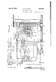
Fig. 1 is a top plan view partly broken awav and in horizontal section.
Fig. 2 is a fragmentary top plan view partly in section.
Fig. 3 is a vertical sectional view on line 3 3 of Fig. 2.
Fig. 4 is a similar view'on line 4 4 of Fig. 2.
The drawings above briefly described, disclose the preferred form of construction and while this construction will be herein specifically explained, it is to be understood that within the scope of the invention as claimed, numerous variations may be made.
The numeral 5 denotes a base frame upon one end of which, an electric motor 6 isv mounted. This motor is of .the single phase, induction repulsion, alternating current type. At the other end of the frame 5, an in-f su ating base 7 is secured, and between this base and the motor 6, are two transverse plates 8-9 which are spaced apart to provide a slot 10. At the ends of the insulating Shaft 12 is provided with a threaded portion 19 passing through a traveling member such as a block 20, rotation of which is prevented by a rod 21 secured to the bearings 11 and passing slidably through an opening in said block; Preferably, the block 2O is provided with a soft metal lining 22, such as babbitt, threaded to engage the hard metal threads 19 of the shaft 12. Thus, in case` of short circuit or other Cause, permitting the threaded shaft portion or screw 19 to force the block 20 against one or the other of the bearings 11, the soft metal thread of the lining will merelv strip if the screwT continues to operate, instead of causing injury to other parts.
The block 20 carries a traveling contact 23 adapted to bridge between one contact track 24 and a parallel contact track formed of relatively adjustable sections 25, both of these tracks being carried by the insulating base 7. When the machine is at rest, the
traveling contact 23 is disengaged'from at' least one of the contact tracks, and in some adjustments of the machine, from both of them. However, after the motor has been `initially started, screw 19 causes traveling of the block 20'to bring said traveling contact 23 upon both contact tracks 24-25, and
these parts then constitute a limit switch for directing current to the motor for a predetermined time, controlled byV adjustmentof the track sections 25, according to the distance which it is desired to drive the chain 18.
At one side of the screw 19, a current reversin switch 26 is provided, the construction o which is. covered by my co-pending U..S. application, Serial No. 266,842, filed April 2, 1928. This reversingl switch embodies a metal base 27 resting upon the .plates 8--9 and secured to them by clampingbolts 28 passing through the slot 10, permitting adjustment of the reversing switch 2 6 .longitudinally ofthe screw 19.' Rising rigidly `from base 27, is a wall 29 with which certain arts hereinafter described, are associated. Secured upon the basef27, is an insulating -base 30 upon which two switch blades `3l-32,
are pivoted between their ends. Co-open' able with the opposite ends of the blade 31. are two contacts 33-34 carried by. the base 30. Co-operable with one end of the blade 32, are two contacts 35-36, and co-operable with the other end of said blade 32are two additional contacts 37-38. The two blades 31-32 are secured to' an insulator 39 for movement simultaneously, and when said blades are swung in one direction, they engage the contacts 33-35-36 but disengage from the contacts 34-37-38. Similarly, upon swinging of the blades 31-32 inthe other direction, they disengage from the contacts 33-35-36 and engage the contacts 34-37--38. The contacts 33-37 are crossconnected by a conductor 40, and a similar conductor 41 connects the contacts 34.-36.
The end of the insulator 39, toward the screw 19, is provided with lugs 42 which project outwardly beyond the wall 29 and are spaced apart longitudinally of said screw. (lo-operable with these lugs, is a Yshaped switch actuator 43 which is pivoted at 44 to the wall 29, the lower end of said actuator being connected with an appropriate spring o device 45 which serves t-o rapidly shiftit to its final position in one direction or the other, when said actuator is moved in said direction slightly past a dead center position. The arms 46 of the actuator 43, constitute trips for co-operation with an additional trip 47 on the block 20, for forcing said actuator slightly past the above-nained dead center position, when said member 20 moves in one direction or the other. The distance between the trips 46 is very small compared with the travel of the block 20, so that the reversing switch 26 will be thrown from one position to the other while the limit switch 2324-e25 is in circuit-closing position, for a purpose to hereinafterappear. Obviously, due to the construction of the actuating means 42-43--45, etc., said switch will be rapidly thrown from one position to another, with such speed that even though' current is at that time being passed through the switch to the motor 6,
the speedof the latter will not be affected. Moreover, it may here be explained that although it is unusual to throw alcurrent-reversing switch for a motor to obtain a result other than reversing of the latter. as soon as possible, such prompt reversal does not take place' in connection with the present inven-l tion. The switch 26 is not thrown from one position to another until the motor 6 has attained speed and its brushes have consequently kicked out to armature-short-circuiting position. Promptly after the brushes reach this position however, quickv vrence ta res place, the door is immediately backed away-from the obstacle with which it has come in contact.
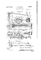
A brake shoe 48 is provided for the pulley 13, said shoe being secured to one end of a lever 49 which is fulcrumed near said Aend to the frame 5,-es indicated at 50. Connected to the other end of lever 49 is an'appropriate spring device 51 which is anchored to the lbase 5, said spring device exerting a constant force to `swing thelever 49 in brake-applying direction. A solenoid 52 however, is connected to the lever 49 for moving it to brakereleasing position when-the motor 6 is to be started, and for holding itin such position until the motor is cut oit.
Motorestartin switches 53-54 are provided for initiall 4 irecting current through the solenoid 52,'t e reversing switch 26 and the motor 6, to start the latter, switch 53 being operable to effect motor rotation in one direction, forfinstance, toopen a door, and switch 54 being used lto effect reverse rotation of the motor to closethe door. When switch 53 or 54 is closed,the current in traveling to the motor 6, passesthrough'either the contact 35 and one end of the switch blade 32 or through the contact 38 and the' other end' ofsaid switch blade, and necessarily the starting switch is held closed until the limit switch 23-24-25,
l is in circuit-com letin position. Then, the
starting switch s ould e released to permit it to open, but evenif said starting switch be v4held closed longer than the period for which the machine is to operate in one direction, n o
injurious results yvillappen. This is due to the fact that as soon as tf'iip 47 of the block 20, ede'cts reversal of the switch 26, the starting circuitnwhich was completed by the starting switch 53 or 54, is automatically Ibroken at the contacv35 or 38, as the case. may be. Hence, even though a person operating the mechanism, does not know that the starting switch should be released immediately after initially starting the motor, and should hold it closed for a longer period, the automatic breaking of the starting circuit at the Contact l35 or 37 insures that the motor 6 shall be placed under the control ofthe limit `switch and taken out of. control of the starting switchjinsuring that said motor shall cstop at the proper time.
Breaking of the starting circuit at the contact 35 or 38 does not break the circuit of the solenoid 52 through which said starting cir cuit has directed current to release the brake broken, the limit switch 23--24-25 has come into play and this'limit switch continues to direct current through said solenoid, holding the brake shoe in released position. Hence, as soon as the limit switch eii'ects opening of the motor circuit, it also de-energizes the sole, noid 52, with the result that the spring device 51 immediately effects brake applicatlon and stops the machine.
' The wiring used, is such as to produce the following functions and it may be varied as desired. The starting switch 53 or 54 must direct current through the solenoid 52 and. through the reversing switch 26, including contact 35 or 38, to eil'ect initial starting of the motor, and obviously this motor will turn in the direction dictated by the position of said reversing switch. The limit switch 23-24-25 must take up the task' of directing current to the mot-or 6, through the solenoid 5.2 and through the reversing switch 26, in-
cluding the Contact 35 or 38, immediatelymember 20 reaches the limit of its predeter' mined travel, must not only eect opening of the motor circuit, but opening of the circuit of the solenoid 52. As one way of accomplishing these results, have shown certain wiring which will now be described.
55 and 56 denote twowires leading from a source of current, wire 55 being providedy with one or more switches 57 to be opened in case of emergency, to discontinue the supply of current to the entire machine. This wire r55 is electrically connected with the 'ontact track sections 25, by one of two clamping bolts 58 which secure said sectionsin adjusted position, these bolts being connected by a conductor 59. Wire 56 leads from the sole-v noid 502. Two wires 60--61 are provided to receive currentofrom the4 wire 55, through switch 53 or 54 respectively. Wire 60 is connected to contact 38 and wire 61 leads to contact 35. From the contact track 24, a wire 62 leads-to the solenoid 52, and a wire 63 eX- tends from wire.62 to the blade 32. Four wires 64-65-66-67 are connected to motor 6. Wire 65 is connected to contact 33; wire 66 is connected to the switch blade 31; and wire 67 connects with the contact 34.
After the limit switch `23-24-25 has closed the circuit of the motor 6 ofthe sole- 'y noid 52, with the reversing switch 26 inthe e position shown in Fig. 1, the current travels as indicated by the arrows in this view, as
long as switch 54 is closed or blade 32 is in Y engagement with contact 35. vIf switch 54 be opened, the current is then directed through the reversing switch to the motor 6, solely by the limitswitch 23--24-25. As
26 reverses the direction of travel of the cur- .smoothly to a standstill.
'now out of control of the switch 54 but if rent to one of the windings of the motor 6, but as the brushes of the latter are then in armature-short-circuiting position, its direction of rotation is not affected. However, if any circumstances should now arise, placing an overload on the motor and consequently decreasing its speed, the brushes move in the usual way to armature-energizing position, and the motor immediatey reverses with the advantages above pointed out. After throwing the limit switch 26, the machine continues to operate until the traveling contact 23 of the limit switch breaks the circuit between the contact tracks 24-25, by moving oii of one or both of these tracks, as the case may be. lVith the current thus broken for the motor 6, the current for the solenoid 52 is also broken, with the rresult that spring 51 immediately moves lever 49 to apply the brake shoe 48, thus bringing the machine The machine is switch 53 be closed, the solenoid 52 is energized and current directed to the motor 6, but due to the position which the reversing switch 26 then occupies, this motor will rotate in the reverse direction. This rotation of course causes similar rotation of the vshaft 12 and causes block 20 to move in the opposite direction from that in which it previ-- ously moved. During its travel, this block effects throwing of the reversing switch 26 without affecting the rotation of the motor 6 and when said block reaches a point at which the limit switch 2:3-24-25 opens the m0- tor and solenoid circuits, the machine comes to rest.
When the invention is .used forv operating a door, I so adjust the reversing switch 26 as to cause throwing thereof immediately after the door starts on its ,closing movement. Hence, in case it should strike an automobile,
'a person, etc., the motor will immediately reverse and the door moved'again to open position.' The adjustability of this switch limit switch. The starting switch in addition to effecting starting of the-motor, initially energizesv the solenoid 52 to release the brake 49, and as soon as the limit switch takes up the work of directing current to the motor,
it also maintains the circuit to the solenoid to hold the brake released. As soon as the limit switch breaks the motor circuit, it also breaks the solenoid circuit to eifect immediate application of thebrake. During each travel of the member 20 in one direction or the other, the switch 26 is thrown to condition the motorA 6 for reversing,` as above described, adding a great element of safety. The switch or switches 57 may obviously be opened in case of emergency to break the current to the entire machine, adding another element otsafety. In case short circuit or other cause should permit continued driving of the machine and consequent jamming of the block 2O against one of the bearings 1l, the threads of the soft metal lining 22 will merely strip instead of injuring any other parts.
Whilein practice, I have used the machine primarily as a door operator, it will be obvious to those skilled in the art that said vmachine as a whole and certain groups of related elements thereof, are not restricted to y this or in fact to any particular field of use. Hence, considerable latitude is allowed within the scope of the invention as claimed.
I claim 1. In combination with a single phase repulsion-induction, electrically reverse motor; means driven by said said motor and connected therewith for automatically reversing the current travel to one winding of said motor promptly after the brushes thereof reach armature-short-circuiting position and for then immediately directing the reversed current continuously to said winding, therebyV conditioning the motor for automatic reversing in case overload should cause motor speed reduction and consequent return Iof the brushes to armature-energizing position.
3. combination, a single phase, repulsion-induction, electrically reversed motor, a
starting switch for the motor, u limit switch synchronized with the motor for directing current to said motor after starting thereof in either direction; a quick-acting reversing switch in circuit with said motor, said starting swi'toch and said limit switch and connected 1n its circuit to reverse 'the current and reversible with said motor, a starting switch for said motor; 'a lim/it switch for directing current to said motor after startin thereof in either direction, said limit switch embodying a traveling circuit making and breaking contact on said traveling member; a quick-acting reversing switch in circuit with said motor, said starting switch and said limit switch and connected in its circuit to reverse the current travel to one winding of the motor and to then immediately' direct the reversed current continuously to said one winding; said'reversing switch having a pair of actuating trips spaced apart along the path of said traveling member a distance con- Y siderably less than the travel of said traveling contact, and a trip on said traveling member co-operable with either of said-pair of trips to throw said reversing switch from one position to theA other promptly after the motor brushes reach armature-short-circuiting position.
5. In combination, la single phase, repulsion-induction, electrically reversed motor, a shaft driven bysaid motor and adapted for effecting movement of a movable object in one direction or the other, said shaft having a threaded portion, a traveling member actu- .ated by said threaded shaft portion, a start-` ing switch for said motor, a limit switch for directing current to the motor after starting thereof in either direction, said limit switch embodying a traveling circuit'making and breaking contact on said traveling member; a
quick-acting reversing switch in circuit withv said motor, said starting switch and said limit switch and connected in its circuit to reverse Ythe current travel to one winding of the motor and to then immediately direct the reversed current Ycontinuously to said one winding; said reversing switch hav-.
ing .a pair of actuating trips spaced apart member co-,operable with either of said pair of trips to throwsaid reversing, switch from one :position to the other promptly after the motor brushes reach armature-short-circuiting position.
6. In combination with an electric motor; a traveling member synchronized with and reversible with `said motor, a starting circuit for7 said motor embodying a normally open starting switch and normally closed switch means; a limit switch for directing current to said motor after starting thereof in either direction; quick-acting switch means for re- 'versingv travel of current to one winding of said motor, a pair of trips spaced apart along l j the path of said traveling member and operatively connected with both said normally closed switch means and said reversing switch means, and a trip on said traveling member co-,operable with either of said pair of trips to simultaneously efect/ opening of said normally closed switch means and shifting of 'I said reversing switch mleans when said traveling member has moved a predetermined amount.
-7. In combination, a single phase, repulsion-induction electrically reversed motor, a screw driven by said motor, a traveling member actuated by said screw, parallel stationary contact tracks parallel'with said screw, a traveling contact on said traveling member adapted to bridge between said tracks to provide a limit switch for the motor, a current reversing switch stationarily mounted near said screw and having a switch'member movable from lone position to another to reverse travel of current to one winding of the motor, stationary contacts co-operable with said movable switch member to form one closed switch when said switch member is in one'pov sition, and another closed switch when said switch member is in its other position, startingswitch means and-wiring for directing currentto the motor t-hrough said reversing switch and one or the other of said stationary contacts according to the position of said movable switch member, wiring whereby said contact-tracks and said traveling contact direct' current to the motor through the reversing switch after starting of said motor, and
qulck-acting means for rapidly shifting said v I Y movable switch member from one position tol the other to simultaneously reverse travel of current to the motor and break the circuit closed by the starting switch, said quick-acting means being active upon movement thereof past a' dead center position, said quick-actingmeans and said traveling member having trips for moving said quick-acting means past said dead center position while said traveling Contact remains on said contact tracks.
8. Astructure as specified in claim 7; together with means for'adjusting said quickacting means longitudinally of the screw to vary the time at which it is moved by said traveling member.
T9. A. method for conditioning a single-4 phase, repulsion-induction, electrically-reasv versed motor for automatic reversing in case of overload, consisting in rapidly reversin the current flow for one wmding of sai motor promptly after the usual motor brushes reach armature-short-circuiting position and continuousl directing current to Asaid one winding,l w ereby overload and consequent return of the brushes to armature-energizing position will cause the motor to reverse.
,10 In testimony whereof I have hereunto aixed my signature. e
CHARLES GORMAN.
Priority Applications (1)
| Application Number | Priority Date | Filing Date | Title |
|---|---|---|---|
| US266841A US1854584A (en) | 1928-04-02 | 1928-04-02 | Door operating means |
Applications Claiming Priority (1)
| Application Number | Priority Date | Filing Date | Title |
|---|---|---|---|
| US266841A US1854584A (en) | 1928-04-02 | 1928-04-02 | Door operating means |
Publications (1)
| Publication Number | Publication Date |
|---|---|
| US1854584A true US1854584A (en) | 1932-04-19 |
Family
ID=23016209
Family Applications (1)
| Application Number | Title | Priority Date | Filing Date |
|---|---|---|---|
| US266841A Expired - Lifetime US1854584A (en) | 1928-04-02 | 1928-04-02 | Door operating means |
Country Status (1)
| Country | Link |
|---|---|
| US (1) | US1854584A (en) |
Cited By (2)
| Publication number | Priority date | Publication date | Assignee | Title |
|---|---|---|---|---|
| US2548709A (en) * | 1946-09-12 | 1951-04-10 | Drexler Charles | Overload automatic reversible control |
| US2562823A (en) * | 1947-03-21 | 1951-07-31 | Charles E Schlytern | Electrical power-driven operator unit |
-
1928
- 1928-04-02 US US266841A patent/US1854584A/en not_active Expired - Lifetime
Cited By (2)
| Publication number | Priority date | Publication date | Assignee | Title |
|---|---|---|---|---|
| US2548709A (en) * | 1946-09-12 | 1951-04-10 | Drexler Charles | Overload automatic reversible control |
| US2562823A (en) * | 1947-03-21 | 1951-07-31 | Charles E Schlytern | Electrical power-driven operator unit |
Similar Documents
| Publication | Publication Date | Title |
|---|---|---|
| US1962475A (en) | Overhead door control means | |
| US1854584A (en) | Door operating means | |
| US1745990A (en) | Automatic stopping and reversal of electromechanically-operated doors and the like | |
| US1952299A (en) | Time relay for power control | |
| US887253A (en) | Valve-operating mechanism. | |
| US1249110A (en) | Electrical operating means for doors. | |
| US1100134A (en) | Controller. | |
| USRE20471E (en) | Motor contooiung device | |
| US2382827A (en) | Reversing split-phase motor | |
| US2308709A (en) | Control system | |
| US1477840A (en) | Controller for driven machines | |
| US1894815A (en) | Control system | |
| US3787725A (en) | Electric garage door opener | |
| US835362A (en) | Operating bulkhead-doors. | |
| US2465332A (en) | Reversing switch control of press machine motors | |
| US869356A (en) | Motor-controller. | |
| US1158824A (en) | Mechanism for raising and lowering shutters or curtains. | |
| US2696580A (en) | Reversible motor control | |
| US1109850A (en) | Electric slow-down device. | |
| US1233854A (en) | Motor-control system. | |
| US2170510A (en) | Automatic position stop mechanism for machine tools | |
| US1897074A (en) | Inertia relay | |
| US1865925A (en) | Electrical door operating mechanism | |
| US1909131A (en) | Door control means for elevators | |
| US1207660A (en) | Automatic safety-stop for line-shafts. |