US1854580A - Compressed air water elevator - Google Patents
Compressed air water elevator Download PDFInfo
- Publication number
- US1854580A US1854580A US552670A US55267031A US1854580A US 1854580 A US1854580 A US 1854580A US 552670 A US552670 A US 552670A US 55267031 A US55267031 A US 55267031A US 1854580 A US1854580 A US 1854580A
- Authority
- US
- United States
- Prior art keywords
- air
- valves
- chamber
- diaphragm
- alternately
- Prior art date
- Legal status (The legal status is an assumption and is not a legal conclusion. Google has not performed a legal analysis and makes no representation as to the accuracy of the status listed.)
- Expired - Lifetime
Links
- XLYOFNOQVPJJNP-UHFFFAOYSA-N water Substances O XLYOFNOQVPJJNP-UHFFFAOYSA-N 0.000 title description 17
- 239000007788 liquid Substances 0.000 description 9
- 238000005192 partition Methods 0.000 description 9
- 208000028659 discharge Diseases 0.000 description 6
- 238000010276 construction Methods 0.000 description 4
- 238000005086 pumping Methods 0.000 description 4
- 230000000295 complement effect Effects 0.000 description 3
- 229920001091 Poly(octyl cyanoacrylate) Polymers 0.000 description 1
- 241000364021 Tulsa Species 0.000 description 1
- DNORZUSMZSZZKU-UHFFFAOYSA-N ethyl 2-[5-(4-chlorophenyl)pentyl]oxirane-2-carboxylate Chemical compound C=1C=C(Cl)C=CC=1CCCCCC1(C(=O)OCC)CO1 DNORZUSMZSZZKU-UHFFFAOYSA-N 0.000 description 1
- 230000000284 resting effect Effects 0.000 description 1
Images

Classifications
-
- F—MECHANICAL ENGINEERING; LIGHTING; HEATING; WEAPONS; BLASTING
- F04—POSITIVE - DISPLACEMENT MACHINES FOR LIQUIDS; PUMPS FOR LIQUIDS OR ELASTIC FLUIDS
- F04F—PUMPING OF FLUID BY DIRECT CONTACT OF ANOTHER FLUID OR BY USING INERTIA OF FLUID TO BE PUMPED; SIPHONS
- F04F1/00—Pumps using positively or negatively pressurised fluid medium acting directly on the liquid to be pumped
- F04F1/06—Pumps using positively or negatively pressurised fluid medium acting directly on the liquid to be pumped the fluid medium acting on the surface of the liquid to be pumped
-
- Y—GENERAL TAGGING OF NEW TECHNOLOGICAL DEVELOPMENTS; GENERAL TAGGING OF CROSS-SECTIONAL TECHNOLOGIES SPANNING OVER SEVERAL SECTIONS OF THE IPC; TECHNICAL SUBJECTS COVERED BY FORMER USPC CROSS-REFERENCE ART COLLECTIONS [XRACs] AND DIGESTS
- Y10—TECHNICAL SUBJECTS COVERED BY FORMER USPC
- Y10T—TECHNICAL SUBJECTS COVERED BY FORMER US CLASSIFICATION
- Y10T137/00—Fluid handling
- Y10T137/8593—Systems
- Y10T137/86493—Multi-way valve unit
- Y10T137/86574—Supply and exhaust
- Y10T137/86582—Pilot-actuated
-
- Y—GENERAL TAGGING OF NEW TECHNOLOGICAL DEVELOPMENTS; GENERAL TAGGING OF CROSS-SECTIONAL TECHNOLOGIES SPANNING OVER SEVERAL SECTIONS OF THE IPC; TECHNICAL SUBJECTS COVERED BY FORMER USPC CROSS-REFERENCE ART COLLECTIONS [XRACs] AND DIGESTS
- Y10—TECHNICAL SUBJECTS COVERED BY FORMER USPC
- Y10T—TECHNICAL SUBJECTS COVERED BY FORMER US CLASSIFICATION
- Y10T137/00—Fluid handling
- Y10T137/8593—Systems
- Y10T137/86493—Multi-way valve unit
- Y10T137/86574—Supply and exhaust
- Y10T137/8667—Reciprocating valve
- Y10T137/86686—Plural disk or plug
Definitions
- This invention relates to pumps for raising liquid. It is particularly designed for pumping water but, obviously, it may be used for other purposes.
- This application con-v tains the same subject matter as my abandoned application No. 327,585.
- the invention contemplates the provision of means whereby air may be utilized for forcing water from a well, reservoir or the like and novel means is provided whereby a motor may be installed in the discharge line for operating certain control valves.
- the motor may consist of a meter of approved construction.
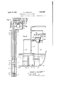
- Fig. l is an elevational View of a pumping unit constructed in accordance with my invention.
- Fig. 2 is an enlarged sectional view of the accumulating tanks or compartments and the air lines and discharge pipe, the latter being shown in elevation.
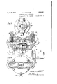
- Fig. 3 is a view partly in section and partly in elevation of the meter and the aircontrolling mechanism.
- Fig. 4 is a sectional view on the line 4-4 of Figure 3.
- Fig. is an enlarged sectional view on the line 55 of Figure 3, a portion of the meter being in elevation.
- Fig. 6 is a sectional view on the line 6-6 of Figure 3.
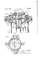
- Fig. 7 is a diagrammatical view of the pumping system and Fig. 8 is a diagrammatical view of a slightly modified form of the pumping system.
- 1 designates a well containing liquid to be pumped.
- 2 is a standpipe resting on an anchor 3 in the well.
- 4 and 5 are tanks supported in spaced relation within the well, preferably by the standpipe 2.
- the tanks 4 and 5 have inlet openings 6 and 7 at the bottoms of the respective tanks which may be closed by upwardly moving checkvalves 8 and 9 respectively, one for each tank.
- strainers 10 which the rod 37 slides.
- the water is adapted to be discharged through the standpipe 2 by first entering the inlet openings 12 and 13, adapted to be closedby the check-valves 14 and. 15.
- the check valves are carried by fittings 16 and 17 in which the openings 12 and 13 are provided (see Fig. 2).
- the standpipe dis charges at a suitable point above the ground through a meter 18.
- the tanks are submerged below the level of the liquid column 19.
- the tanks are designed to accumulate alternately and to discharge alternately so that practically a continuous stream of water will flow through the pipe 2, the discharge being shown at 20 (see Fig. 7). It is obvious that when the tanks are empty, the weight of the water caused by the head will lift the valves 8 and 9 and accumulate in the tanks. When the tanks are sufliciently filled, the
- the two branch pipes 28 and 29 discharge into a valve casing 30 having air supply chambers 31 and 32 provided with exhaust openings 33 and 34 which may be alternately opened and closed by the valves 35 and 36 on the transverse rod or stem 37
- the valve chamber is provided with bushings 38 and 39 having seats 40 and 41 against which the double-faced valves 35 and 36 may alternately seat. That is, when the exhaust port 33 is closed, the exhaust port 34 is open and vice versa.
- the air supply chambers 31 and 32 are respectively connected to the air pipes 23 and 24.
- the rod carrying the valves 35 and 36 is connected to two diaphragms 42 and 43, between which is a web 44 having a guide bushing 45 through
- the web 44 tovalve chambers 46 and 47 have extensions 50 and 51 in which are exhaust ports 52 and 53 adapted to be closed by the pin-valves 54 and 55 passing through bushings 56 and 57 (see Fig. in chamber below and separate from the equalizing pressure chambers '46 and 47.
- These valves are urged into closing position by the closing levers 58 and 59 fulcrumed at 60 and 61 (see Fig.
- the diaphragm 42 will urge the valve stem "or rod 37 from left to right, unseating valve '35 from the exhaust side of chamber 31 by seating on seat 40.
- the valve 36 closes the exhaust side of chamber 32 and unseats from seat 41 so air will pass into pipe 24.
- This action causes the tank 5 to accumulate air and discharge water or other liquid as the case may be.
- the air pressure in tank 4 is relieved because the eiihaust port 33 is open, therefore, the valve 14 will seat of its own weight.
- the valve 8 will unseat, allowing water or other liquid to accumulate in tank 4, forcing the air above it through pipe 23 to exhaust.
- lVhenthe valve 55 is 'unsea'ted by thecam or lug 67, the chamber 47 exhausts while the pressures .in chambers 31 and 46 are equal and opposite. This causes a preponderating pressure to be exerted against the right hand face of the diaphragm '43, forcing it together with the diaphragm 42 and the valve stem 37 from right to left (see Fig.
- the exhaust port 34 is now. tincever ed, the valve 36 beingseated on seat 41 while the valve 35 closes the exhaust port 33 and uncovers the port surrounded by the seat 40.
- the parts will be injthe positionsshown in Fig; 5.
- An air valving mechanism comprising a "casi-n g having an inlet, air supply outlets and exhaust ports, a diaphragm 1n the casing, a
- valve stem carried the diaphragm, valves on the stem for opening and closingthe exhaust ports to admit air through the pipes to exhaust it therefrom and motor actuated valving means associated with theca'sing and diaphragm to cause air pressure to preponderate alternately on oppositesideso f the diaphragm to cause movement thereofto actuate the valves.
- An air controlling means for compressed air liquid elevators comprising a'casing having a central chamherand two pairs of end chambers, the end chamber of "each pair nearest the center having an air inlet, the other air 'chal'nber of each pair having its an air exhaust port and an air discharge port communicating with the pipe to deliver air to a tank, a valve stem having valves on its ends to alternately cut oil communication between the air chamber of each pair nearest the center and the air chamber of the other pair and the exhaust port, a diaphragm mechanism actuated by the air admitted to the casing for operating the valve stem, the diaphragm mechanism comprising two diaphragms with a space between them, the space being divided into two independent compartments communicating the central chamber with one of each pair of end chambers through a port in each diaphragm, each compartment having an exhaust port and means for alternately opening and closing the exhaust ports for the compartments.
- An air controlling means for compressed air liquid elevators comprising a casing having a central chamber and two pairs or" end chambers, the end chamber of each pair nearest the center having an air inlet, the other air chamber of each pair having an air exhaust port and an air discharge port communicating with the pipe to deliver air, a vlve stem having valves on its ends to alternately out off communication between the air chamber of each pair nearest the center and the air chamber of the other pair and the exhaust port, a diaphragm mechanism actuated by the air admitted to the casing for operating the valve stem, the diaphragm mechanism comprising two diaphragms with a space between them, the space being divided into two independent compartments communicating the central chamber with one 01" each pair of end chambers through a port in each diaphragm, each compartment having an exhaust port and motor actuated means for alternately opening and closing the exhaust ports for the compartments.
- An air controlling mechanism compris' ing a casing having a central partition, perforate diaphragms on opposite sides of the partition dividing the casing into a central compartmental chamber, ported partitions spaced from the diaphragm dividing each end of the casing into a pair of end compartments communicating one with the other through a port, the outer end compartments having openings to communicate with pipes through which air is to be supplied, each end compartment having an exhaust port, each end compartment nearest a diaphragm having an inlet port, a valve stem carried by the diaphragm, valves on the ends of the stem for alternately opening the exhaust port and closing communication between complementary end chambers and vice versa and means for alternately exhausting air from the respective compartments of the central chamber.
- An air controlling mechanism comprising a casing having a central partition, perforate diaphragms on opposite sides of the partition dividing the casing into a central compartmental chamber, ported partitions spaced from the diaphragm dividing each end ofthe casing into a pair of end compartments communicating one with the other through a port, the outer end compartments having openings to communicate with pipes through which air is to be supplied, each end compartment having an exhaust port, each end compartment nearest a diaphragm having an inlet port, a valve stem carried by the diaphragm, valves on the ends of the stem for alternately opening the exhaust port and closing communication between complementary end chambers and vice versa, means for alternately exhausting air from the respective compartments of the central chamber, said means comprising lever actuated valves for exhaust ports in the compartments of the central chamber and a rotatable cam for operating the lever actuated valves.
- An air controlling mechanism comprising a casing having a central partition, perforate diaphragms on opposite sides of the partition dividing the easing into a central compartmental chamber, ported partitions spaced from the diaphragm dividing each end of the casing into a pair of end compartments communicating one with the other through a port, the outer end compartments having openings to communicate with pipes through which air is to be supplied, each end compart' ment having an exhaust port, each end compartment nearest a diaphragm having an inlet port, a valve stem carried by the diaphragm, valves on the ends of the stem for alternately opening the exhaust port and closing communication between complementary and chambers and vice versa, means for alternately exhausting air from the respective compartments of the central chamber, said means comprising pin valves, springpressed pivoted levers having their outer ends engaging the pin valves and a rotatable disc having a lug for intermittently pressing against the levers to actuate them to unseat the pin valves.
Landscapes
- Engineering & Computer Science (AREA)
- Mechanical Engineering (AREA)
- General Engineering & Computer Science (AREA)
- Reciprocating Pumps (AREA)
Description
April 19, 1932. T. E. CROCKETT COMPRESSED AIR WATER ELEVATOR 4 Shee-Sheet 1 Original Filed Dec. 21, 1928 Fla! INVENTOR 77/0/115 E C'POCA/ETT 95 MA TTORNEY April 19, 1932. T. E. CROCKETT 1,854,530
COMPRESSED AIR WATER ELEY ATOR Original Filed Dec. 21, 1928 4 Shee'ts-Sheet 2 11v VENTOR IHOMHS (806K577 BY M/ITTORNEY April 19, 1932. T. E. CROCKETT COMPRESSED AIR WATER ELEVATOR Original Filed Dec. 21, 1928 4 sheets sheet 3 [N VENTOR THO/"l5 CROZKETT Patented Apr. 19, 1932 UNITED STATES PATENT OFFICE THOMAS E. CROCKET'I, OF TULSA, OKLAHOMA, ASSIGNOR TO CYRUS E. COFFEE, OF
. ST. LOUIS COUNTY, MISSOURI COMPRESSED AIR WATER ELEVATOR Refiled for abandoned application Serial No. 327,585, filed December 21, 1928. This application filed.
July 23, 1931.
This invention relates to pumps for raising liquid. It is particularly designed for pumping water but, obviously, it may be used for other purposes. This application con-v tains the same subject matter as my abandoned application No. 327,585.
The invention contemplates the provision of means whereby air may be utilized for forcing water from a well, reservoir or the like and novel means is provided whereby a motor may be installed in the discharge line for operating certain control valves. The motor may consist of a meter of approved construction.
In order to comprehend the novelty of the invention and the advantages resulting therefrom, reference should behad to the accompanying drawings in which:
Fig. l is an elevational View of a pumping unit constructed in accordance with my invention.
Fig. 2 is an enlarged sectional view of the accumulating tanks or compartments and the air lines and discharge pipe, the latter being shown in elevation.
Fig. 3 is a view partly in section and partly in elevation of the meter and the aircontrolling mechanism.
Fig. 4 is a sectional view on the line 4-4 of Figure 3.
Fig. is an enlarged sectional view on the line 55 of Figure 3, a portion of the meter being in elevation.
Fig. 6 is a sectional view on the line 6-6 of Figure 3.
Fig. 7 is a diagrammatical view of the pumping system and Fig. 8 is a diagrammatical view of a slightly modified form of the pumping system.
Referring now to the drawings by numerals of reference, 1 designates a well containing liquid to be pumped. 2 is a standpipe resting on an anchor 3 in the well. 4 and 5 are tanks supported in spaced relation within the well, preferably by the standpipe 2. The tanks 4 and 5 have inlet openings 6 and 7 at the bottoms of the respective tanks which may be closed by upwardly moving checkvalves 8 and 9 respectively, one for each tank.
At the bottoms of the tanks are strainers 10 which the rod 37 slides.
Serial No. 552,670.
and 11. The water is adapted to be discharged through the standpipe 2 by first entering the inlet openings 12 and 13, adapted to be closedby the check-valves 14 and. 15. The check valves are carried by fittings 16 and 17 in which the openings 12 and 13 are provided (see Fig. 2). The standpipe dis charges at a suitable point above the ground through a meter 18. The tanks are submerged below the level of the liquid column 19. The tanks are designed to accumulate alternately and to discharge alternately so that practically a continuous stream of water will flow through the pipe 2, the discharge being shown at 20 (see Fig. 7). It is obvious that when the tanks are empty, the weight of the water caused by the head will lift the valves 8 and 9 and accumulate in the tanks. When the tanks are sufliciently filled, the
'valves will seat upon the seats 21 and 22 in the respective tanks. Means is provided for dischar ing the tanks through the pipe 2. To this end, I have provided air pressure pipe 23 for the tank 4 and a like pipe 24 for the tank 5. The two pipes are supplied with air from an air tank 25 in which the pressure is maintained through the medium of an air compressor 26. In the line between the discharge pipe 27 of the air supply tank 25 and the pipes 23 and 24 is an air controlling mechanism operated by a part of the meter 18. The air controlling mechanism is best shown in Figures ,3 to 6, both inclusive. The two branch pipes 28 and 29 discharge into a valve casing 30 having air supply chambers 31 and 32 provided with exhaust openings 33 and 34 which may be alternately opened and closed by the valves 35 and 36 on the transverse rod or stem 37 The valve chamber is provided with bushings 38 and 39 having seats 40 and 41 against which the double- faced valves 35 and 36 may alternately seat. That is, when the exhaust port 33 is closed, the exhaust port 34 is open and vice versa. The air supply chambers 31 and 32 are respectively connected to the air pipes 23 and 24. The rod carrying the valves 35 and 36 is connected to two diaphragms 42 and 43, between which is a web 44 having a guide bushing 45 through The web 44 tovalve chambers 46 and 47 have extensions 50 and 51 in which are exhaust ports 52 and 53 adapted to be closed by the pin- valves 54 and 55 passing through bushings 56 and 57 (see Fig. in chamber below and separate from the equalizing pressure chambers '46 and 47. These valves are urged into closing position by the closing levers 58 and 59 fulcrumed at 60 and 61 (see Fig. 3) and between the inner ends of the levers and the web 62 which so arates the chamber 63 in which the levers are located from the equalizing chambers 46 and 47 are expansion springs 64 and 65, tending to urge the valve closed. The valves are alternately'opened and closed by 'a rotating disc 66 in the meter 18. This disc carries a cam 6? in the form of a lug which, as it rotates with the disc 66, causes the inner ends of the levers to ride over it compressing the springs and opening the valves 54 and 55. As the valve 54 is opened, the air from chamber 46 exhausts so that there is a prepondera'ting pressure in chamber 31 over chamber 46. Valve 55 is still closed so that the pressures in chambers 32 and 47 are equal and opposite. Consequently, the diaphragm 42 will urge the valve stem "or rod 37 from left to right, unseating valve '35 from the exhaust side of chamber 31 by seating on seat 40. At the same time, the valve 36 closes the exhaust side of chamber 32 and unseats from seat 41 so air will pass into pipe 24. This action causes the tank 5 to accumulate air and discharge water or other liquid as the case may be. At the same time, the air pressure in tank 4 is relieved because the eiihaust port 33 is open, therefore, the valve 14 will seat of its own weight. The valve 8 will unseat, allowing water or other liquid to accumulate in tank 4, forcing the air above it through pipe 23 to exhaust. lVhenthe valve 55 is 'unsea'ted by thecam or lug 67, the chamber 47 exhausts while the pressures .in chambers 31 and 46 are equal and opposite. This causes a preponderating pressure to be exerted against the right hand face of the diaphragm '43, forcing it together with the diaphragm 42 and the valve stem 37 from right to left (see Fig. The exhaust port 34 is now. tincever ed, the valve 36 beingseated on seat 41 while the valve 35 closes the exhaust port 33 and uncovers the port surrounded by the seat 40. In other words,.the parts will be injthe positionsshown in Fig; 5. Air now enters the pipe 23, putting pressure on the liquid in tank 4 so as to force it into the standpipe 2, the valve 8 at this time being seated. Since the tank 5, air pipe 24 and its connections are open to atmosphere, water may now accumulate in the tank 5. So as soon as one tank is emptied, another will be filled and ready to discharge into the pipe 2. This operation may continue so long as there is liquid to be raised, an air supply for raising it and an operative control mechanism for alternately admitting air pressure to the tanks and alternately exhaust-ing it from the tanks. I prefer to co-ordinate the air control mechanism with the meter because the meter can be arranged so that it must pass a given quantity of water from one tank before air is admitted into the other tank, this insuring the complete emptying of the tank each time water is passed from In Figure 8 I have shown a slightly modified form of the same generic conception of my invention in which the tanks 4 and 5 may be submerged and deliver water into the pipe 2, the tanks being supplied with air pressure through pipes 23 and 24 from the mechanism generically designated 30 controlled by the meter 18. The only essential difference between this construction and that of the preferred form is that the meter is a by-pass meter in the bypass pipe 68. The reason for this construction is that where large quantities of water are to be passed through the pipe 2, as from lake's, rivers or reservoirs, the air controlling mechanism can be operated from the usual bypass meter, a device well. understood by those skilled in the art.
The above description in connection with the accompanying drawings will clearly in- I dicate the utility and novelty of my invention and while I have specifically illustrated what to me at this time appears to be the most desirable form of this invention, 1 do not wish to be limited to the exact details of construction shown. I
Whatl claim and desire to secure by Letters-Patent is 1. An air valving mechanism comprising a "casi-n g having an inlet, air supply outlets and exhaust ports, a diaphragm 1n the casing, a
valve stem carried the diaphragm, valves on the stem for opening and closingthe exhaust ports to admit air through the pipes to exhaust it therefrom and motor actuated valving means associated with theca'sing and diaphragm to cause air pressure to preponderate alternately on oppositesideso f the diaphragm to cause movement thereofto actuate the valves.
2. An air controlling means for compressed air liquid elevators comprisinga'casing having a central chamherand two pairs of end chambers, the end chamber of "each pair nearest the center having an air inlet, the other air 'chal'nber of each pair having its an air exhaust port and an air discharge port communicating with the pipe to deliver air to a tank, a valve stem having valves on its ends to alternately cut oil communication between the air chamber of each pair nearest the center and the air chamber of the other pair and the exhaust port, a diaphragm mechanism actuated by the air admitted to the casing for operating the valve stem, the diaphragm mechanism comprising two diaphragms with a space between them, the space being divided into two independent compartments communicating the central chamber with one of each pair of end chambers through a port in each diaphragm, each compartment having an exhaust port and means for alternately opening and closing the exhaust ports for the compartments.
3. An air controlling means for compressed air liquid elevators comprising a casing having a central chamber and two pairs or" end chambers, the end chamber of each pair nearest the center having an air inlet, the other air chamber of each pair having an air exhaust port and an air discharge port communicating with the pipe to deliver air, a vlve stem having valves on its ends to alternately out off communication between the air chamber of each pair nearest the center and the air chamber of the other pair and the exhaust port, a diaphragm mechanism actuated by the air admitted to the casing for operating the valve stem, the diaphragm mechanism comprising two diaphragms with a space between them, the space being divided into two independent compartments communicating the central chamber with one 01" each pair of end chambers through a port in each diaphragm, each compartment having an exhaust port and motor actuated means for alternately opening and closing the exhaust ports for the compartments.
4. An air controlling mechanism compris' ing a casing having a central partition, perforate diaphragms on opposite sides of the partition dividing the casing into a central compartmental chamber, ported partitions spaced from the diaphragm dividing each end of the casing into a pair of end compartments communicating one with the other through a port, the outer end compartments having openings to communicate with pipes through which air is to be supplied, each end compartment having an exhaust port, each end compartment nearest a diaphragm having an inlet port, a valve stem carried by the diaphragm, valves on the ends of the stem for alternately opening the exhaust port and closing communication between complementary end chambers and vice versa and means for alternately exhausting air from the respective compartments of the central chamber.
5. An air controlling mechanism comprising a casing having a central partition, perforate diaphragms on opposite sides of the partition dividing the casing into a central compartmental chamber, ported partitions spaced from the diaphragm dividing each end ofthe casing into a pair of end compartments communicating one with the other through a port, the outer end compartments having openings to communicate with pipes through which air is to be supplied, each end compartment having an exhaust port, each end compartment nearest a diaphragm having an inlet port, a valve stem carried by the diaphragm, valves on the ends of the stem for alternately opening the exhaust port and closing communication between complementary end chambers and vice versa, means for alternately exhausting air from the respective compartments of the central chamber, said means comprising lever actuated valves for exhaust ports in the compartments of the central chamber and a rotatable cam for operating the lever actuated valves.
6. An air controlling mechanism comprising a casing having a central partition, perforate diaphragms on opposite sides of the partition dividing the easing into a central compartmental chamber, ported partitions spaced from the diaphragm dividing each end of the casing into a pair of end compartments communicating one with the other through a port, the outer end compartments having openings to communicate with pipes through which air is to be supplied, each end compart' ment having an exhaust port, each end compartment nearest a diaphragm having an inlet port, a valve stem carried by the diaphragm, valves on the ends of the stem for alternately opening the exhaust port and closing communication between complementary and chambers and vice versa, means for alternately exhausting air from the respective compartments of the central chamber, said means comprising pin valves, springpressed pivoted levers having their outer ends engaging the pin valves and a rotatable disc having a lug for intermittently pressing against the levers to actuate them to unseat the pin valves.
In testimony whereof I aflix my signature.
THOMAS E. CROCKETT.
Priority Applications (1)
| Application Number | Priority Date | Filing Date | Title |
|---|---|---|---|
| US552670A US1854580A (en) | 1931-07-23 | 1931-07-23 | Compressed air water elevator |
Applications Claiming Priority (1)
| Application Number | Priority Date | Filing Date | Title |
|---|---|---|---|
| US552670A US1854580A (en) | 1931-07-23 | 1931-07-23 | Compressed air water elevator |
Publications (1)
| Publication Number | Publication Date |
|---|---|
| US1854580A true US1854580A (en) | 1932-04-19 |
Family
ID=24206298
Family Applications (1)
| Application Number | Title | Priority Date | Filing Date |
|---|---|---|---|
| US552670A Expired - Lifetime US1854580A (en) | 1931-07-23 | 1931-07-23 | Compressed air water elevator |
Country Status (1)
| Country | Link |
|---|---|
| US (1) | US1854580A (en) |
Cited By (1)
| Publication number | Priority date | Publication date | Assignee | Title |
|---|---|---|---|---|
| US5248243A (en) * | 1992-01-22 | 1993-09-28 | World Pump Corporation | Pneumatically operated and controlled fluid pump |
-
1931
- 1931-07-23 US US552670A patent/US1854580A/en not_active Expired - Lifetime
Cited By (1)
| Publication number | Priority date | Publication date | Assignee | Title |
|---|---|---|---|---|
| US5248243A (en) * | 1992-01-22 | 1993-09-28 | World Pump Corporation | Pneumatically operated and controlled fluid pump |
Similar Documents
| Publication | Publication Date | Title |
|---|---|---|
| US1854580A (en) | Compressed air water elevator | |
| US1779319A (en) | Sewage-ejecting mechanism | |
| US2549620A (en) | Pumping mechanism | |
| US1297836A (en) | Flushing-valve. | |
| US2685297A (en) | Air charger | |
| US1716533A (en) | Air or gas compressing system | |
| US2206447A (en) | Pumping system | |
| US1356684A (en) | Pump and pumping system | |
| US3404567A (en) | Apparatus for eliminating air flow through fluid meters | |
| US2247911A (en) | High pressure water closet | |
| US1517594A (en) | Pneumatic pump | |
| US629577A (en) | Pump. | |
| US615812A (en) | Automatic relief-valve for pumps | |
| US1734687A (en) | Automatic stop cock | |
| US1380603A (en) | Pneumatic pump | |
| US905210A (en) | Pneumatic pump. | |
| US1255972A (en) | Pump and pumping system. | |
| US1575851A (en) | Means for controlling the admission of water to tanks | |
| US990085A (en) | Subterranean pumping system. | |
| US722968A (en) | Air-compressor. | |
| US330669A (en) | bennett | |
| US1356130A (en) | Valve | |
| US1256092A (en) | Pump. | |
| US1636626A (en) | Return trap | |
| RU65987U1 (en) | PNEUMATIC DISPLACEMENT PUMP |