US1854573A - Pipe holder for well pipes - Google Patents
Pipe holder for well pipes Download PDFInfo
- Publication number
- US1854573A US1854573A US547732A US54773231A US1854573A US 1854573 A US1854573 A US 1854573A US 547732 A US547732 A US 547732A US 54773231 A US54773231 A US 54773231A US 1854573 A US1854573 A US 1854573A
- Authority
- US
- United States
- Prior art keywords
- rods
- pipe
- plates
- jaws
- yokes
- Prior art date
- Legal status (The legal status is an assumption and is not a legal conclusion. Google has not performed a legal analysis and makes no representation as to the accuracy of the status listed.)
- Expired - Lifetime
Links
- 239000000969 carrier Substances 0.000 description 5
- IHPYMWDTONKSCO-UHFFFAOYSA-N 2,2'-piperazine-1,4-diylbisethanesulfonic acid Chemical compound OS(=O)(=O)CCN1CCN(CCS(O)(=O)=O)CC1 IHPYMWDTONKSCO-UHFFFAOYSA-N 0.000 description 4
- 239000007990 PIPES buffer Substances 0.000 description 4
- 238000010276 construction Methods 0.000 description 2
- 230000000994 depressogenic effect Effects 0.000 description 1
- 239000007787 solid Substances 0.000 description 1
Images
Classifications
-
- E—FIXED CONSTRUCTIONS
- E21—EARTH OR ROCK DRILLING; MINING
- E21B—EARTH OR ROCK DRILLING; OBTAINING OIL, GAS, WATER, SOLUBLE OR MELTABLE MATERIALS OR A SLURRY OF MINERALS FROM WELLS
- E21B19/00—Handling rods, casings, tubes or the like outside the borehole, e.g. in the derrick; Apparatus for feeding the rods or cables
- E21B19/12—Rope clamps ; Rod, casings or tube clamps not secured to elevators
Definitions
- This invention relates to a device for facilitating the lowering and pulling of pipes in wells and the like, the general object of this invention being to provide a frame having a pair of gripping members at the lower part thereof between which a pipe passes, and a number of toothed jaws at its upper end for gripping the pipe with hand operated means for moving the upper jaws to rem lease position and at the same time slightly spreading apart the lower gripping means.
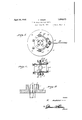
- Figure 1 is a top plan view of the invention.
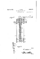
- Figure 2 is a longitudinal sectional view.
- Figure 3 is a similar view taken at right angles to Figure 2.
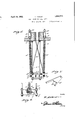
- Figure A is a transverse sectional view looking toward the lower end of the device.
- Figure 5 is a vertical sectional view through the upper end corners of the device showing the gripping generally.
- Figure 6 is a side view of the lower part of the device.
- Figure 7 is a View of one of the pivoted members.
- Figure 8 is a view showing the upper end of one of the frame rods, a bracket, and a nut for holding the bracket on the bar, the parts being separated.
- the numeral 1 indicates the head part of the device which is formed with a flange 1 and with a circular centrally arranged opening2. The walls of this open ing are formed with T-shaped slots 3 which 1931. Serial No. 547,732.
- rods 5 have their upper ends passing through holes in the flange 1 with upper and '60 lower nuts 6 on said rods for holding them to the flange 1.
- These rods 5 have their lower ends threaded in a vertically arranged plate '7 having its ends rolled to receive a pair of the rods and a similar platec'? has its ends rolled to receive the lower end of the other pair of rods as clearly shown in Figure 4-.
- the upper and lower cross pieces 8 connect the rods together and these cross pieces and the plates 7 and 7 form a rectangular frame which is held in place by the upper and lower nuts 9 on each rod.
- Each of the plates 7 and 7 is formed with an opening '10 at its center which passes through the upper edge of the plate and a pair of clamping plates 11 having their ends passing through the openings 10, the central portions of the plates 11 being bowed outwardly as shown'at- 11 to form clamping bars.
- a bolt 12 passes through holesat each end of the pair of plates 11. and a spring 13 is placed on each bolt 12 between the plates and tends to move the plates 11 apart.
- a yoke 14 carries each bolt 12 and the lower end of the rod 15 passes through the bight of each yoke 14: and is secured thereto by a nut 16.
- These rods 15 pass through enlarged holes 17 in the flange 1 of the upper member 1 and an L-shaped arm 18 is fastened to the upper end of each rod 15 by a nut 19.
- a hand lever 96 20 is pivoted to a bracket 21 on the member 1 and has its yoke end 22 having its extremity in hook shape as shown at 23, these hook portions passing through slots 24: in the members 18.
- Cross rods 26 have their lower ends connected with the yokes 14 and the upper end of each cross-rod is connected to the lower end of a jaw 4 so that the upward movement of the yokes will be imparted to the jaws 4.
- a pair of oppositely arranged plate like members 27 is pivoted to each plate 7, 7, one on the outer face of the plate and the other in the inner face and the inner end of each of these members is forked with one prong longer than the other and the bight wall hav ing two angles as shown at 28 in Figure 7. The prongs of these forks straddle the outer ends of the plates 11 as shown in Figure l.
- the spring 25 normally holds the parts in lowered position with the jaws 4 in lowered position and in a position to grip a pipe passing through the device and the gripping plates 11 are also in a position to grip the pipe passed through the device.
- the device operates in the following manner As the pipe is being raised from the well, the cuifs or joints thereon will strike clamps 11 and open the same for the passage of the cuffs or joints automatically. The same operation applies to the upper jaws for as the cuff strikes the lower ends of the jaws it forces them up and apart to permit the passage of the cuff or joint.
- the purpose of the fork members 27 is to force the ends of clamps 11 into openings 10, thus tightening the clamps on the pipe to a degree that securely sets upper jaws to pipe and at the same time assists in holding the ipe.
- the general working idea of the device is that it is either inserted in the mouth of the well and bolted to the concrete base, or else it is used on top of the concrete base in a frame made for it and bolted to base.
- the pipe being pulled with block and tackle is, therefore, handled automatically on the upward movement, and the pipe being handled with block and tackle on the downward movement, the device is held open with lever to permit free passage of pipe and joints. But in case of accident or the necessity of stopping pipe, the lever is released and stops pipe immediately, thus eliminating any chances of dropping the pipe and losing the well entirely.
- the lower frame composed of two side pieces'and four bars is preferably made of one solid piece with holes in each corner to fasten to rods on head piece.
- the rods 26 are preferably made adjustable as to their lengths.
- a device of the class described comprising a head part, toothed jaws slidably arranged in the head part and moving to release position when moved upwardly, a frame, rods connecting the frame with the head, a pair of gripping plates movably arranged in the frame, carriers for said plates, a hand lever pivotally connected with the head part, means for connecting the hand lever with the carriers, whereby downward movement of the lever will raise the carriers to move the gripping plates upwardly and means connected with the carriers and with the jaws for moving the jaws upwardly as the carriers are moved upwardly.
- a device of the class described comprising a head part having a centrally arranged hole therein and downwardly tapering slots in the walls of said opening, toothed jaws carried by and slidably arranged in the slots and moving away from each other when the jaws are moved upwardly, rods depending from the head part, a frame connected with the lower end of the rods, a pair of gripping plates movably arranged in the frame, springs moving thesame away from each other, a pair of yokes in which the ends of the plates are yieldably supported, rods connected with the yokes, a hand lever, means for connecting the same to the upper ends of said rods whereby tilting movement of the lever will raise the rods and the yoke together with the plates, spring means on, the rods for normally holding the parts in lowered postion, and rods connected with the yokes and with the upper jaws for moving the jaws upwardly as the yokes are moved upwardly.
- a device of the class described comprising a head part having a centrally arranged hole therein and downwardly tapering slots in the walls of said hole, toothed jaws carried by and slidably arranged in the slots and moving away from each other when the jaws are moved upwardly, rods depending from the head part, a frame connected with the lower end of the rod, a pair of gripping plates movably arranged in the frame, springs moving the same away from each other, a pair of yokes in which the ends of the plates are yieldably supported, rods connected with the yokes, a hand lever, means for connecting the same to the upper ends of said rods whereby tilting movement of the lever will raise the rods and the yokes together with the plates, spring means on the rods for normally holding the parts in lowered position, and rods connected with the yokes and with the upper jaws for moving the jaws upwardly as the yokes are moved upwardly, and pivoted fork members carried by the frame with the ends of the plate fittin
- hand lever pivoted on the head part having their fork parts threaded through the slots, rods connecting the yokes with the upper jaw parts and fork members pivoted to the lower frame with the prongs straddling the ends of the gripping plate.
Landscapes
- Engineering & Computer Science (AREA)
- Life Sciences & Earth Sciences (AREA)
- Geology (AREA)
- Mining & Mineral Resources (AREA)
- Mechanical Engineering (AREA)
- Physics & Mathematics (AREA)
- Environmental & Geological Engineering (AREA)
- Fluid Mechanics (AREA)
- General Life Sciences & Earth Sciences (AREA)
- Geochemistry & Mineralogy (AREA)
- Manipulator (AREA)
Description
April 19, 1932. v. ASKEW PIPE HOLDER FOR WELL PIPES Filed June 29, 1951 3 Sheets-Sheet l Inventor 7. Ja/ivw v flltorney V. ASKEW April 19, 1932.
PIPE HOLDER FOR WELL PIPES 5 Sheets-Sheet 2 Filed June 29, 1931- Inventor April 19, 1932. v, s w 1,854,573
PIPE HOLDER FOR WELL PIPES Filed June 29, 1951 3 Sheets-Sheet 3 flllomey I Patented Apr. 19, 1932 .AENT. OFFICE v. ASKEW', or DEL R10, TEXAS PIPE HOLDER FOR WELL PIPES Application filed. June 2% This invention relates to a device for facilitating the lowering and pulling of pipes in wells and the like, the general object of this invention being to provide a frame having a pair of gripping members at the lower part thereof between which a pipe passes, and a number of toothed jaws at its upper end for gripping the pipe with hand operated means for moving the upper jaws to rem lease position and at the same time slightly spreading apart the lower gripping means.
Another object of the invention is to provide spring means for normally holding the parts in a position with the jaws and grip- =16 ping means engaging a pipe to hold the same against movement.
This invention also consists in certain other features of construction and in the combination and arrangement of the several parts to be hereinafter fully described, illustrated in the accompanying drawings and specifically pointed out in the appended claims.
In describing the invention in detail, ref erence will be had to the accompanying drawings wherein like characters denote like or corresponding parts throughout the several views, and in which:
Figure 1 is a top plan view of the invention.
Figure 2 is a longitudinal sectional view.
Figure 3 is a similar view taken at right angles to Figure 2.
Figure A is a transverse sectional view looking toward the lower end of the device.
Figure 5 is a vertical sectional view through the upper end corners of the device showing the gripping generally.
Figure 6 is a side view of the lower part of the device.
Figure 7 is a View of one of the pivoted members.
Figure 8 is a view showing the upper end of one of the frame rods, a bracket, and a nut for holding the bracket on the bar, the parts being separated. 7 p In these drawings, the numeral 1 indicates the head part of the device which is formed with a flange 1 and with a circular centrally arranged opening2. The walls of this open ing are formed with T-shaped slots 3 which 1931. Serial No. 547,732.
slope downwardly and inwardly toward the lower end of the head part. These slots re; ceive the toothed jaw members 3 which are tapered so that the jaw members slide up wardly to release the pipe and as-the jaw members move downwardly, they move toward each other so as to grip a pipe passing through the hole 2. c.
Four rods 5 have their upper ends passing through holes in the flange 1 with upper and '60 lower nuts 6 on said rods for holding them to the flange 1. These rods 5 have their lower ends threaded in a vertically arranged plate '7 having its ends rolled to receive a pair of the rods and a similar platec'? has its ends rolled to receive the lower end of the other pair of rods as clearly shown in Figure 4-. The upper and lower cross pieces 8 connect the rods together and these cross pieces and the plates 7 and 7 form a rectangular frame which is held in place by the upper and lower nuts 9 on each rod. Each of the plates 7 and 7 is formed with an opening '10 at its center which passes through the upper edge of the plate anda pair of clamping plates 11 having their ends passing through the openings 10, the central portions of the plates 11 being bowed outwardly as shown'at- 11 to form clamping bars.
A bolt 12 passes through holesat each end of the pair of plates 11. and a spring 13 is placed on each bolt 12 between the plates and tends to move the plates 11 apart. A yoke 14 carries each bolt 12 and the lower end of the rod 15 passes through the bight of each yoke 14: and is secured thereto by a nut 16. These rods 15 pass through enlarged holes 17 in the flange 1 of the upper member 1 and an L-shaped arm 18 is fastened to the upper end of each rod 15 by a nut 19. A hand lever 96 20 is pivoted to a bracket 21 on the member 1 and has its yoke end 22 having its extremity in hook shape as shown at 23, these hook portions passing through slots 24: in the members 18. I
Springs 25 arearranged on each of the rods 15 and tend to hold the parts in lowered position. Cross rods 26 have their lower ends connected with the yokes 14 and the upper end of each cross-rod is connected to the lower end of a jaw 4 so that the upward movement of the yokes will be imparted to the jaws 4. A pair of oppositely arranged plate like members 27 is pivoted to each plate 7, 7, one on the outer face of the plate and the other in the inner face and the inner end of each of these members is forked with one prong longer than the other and the bight wall hav ing two angles as shown at 28 in Figure 7. The prongs of these forks straddle the outer ends of the plates 11 as shown in Figure l.
From the foregoing it will be seen that the spring 25 normally holds the parts in lowered position with the jaws 4 in lowered position and in a position to grip a pipe passing through the device and the gripping plates 11 are also in a position to grip the pipe passed through the device. Pressing downwardly on the lever 20, its yoke 22 will raise the members 18 and thus the rods 15 will be raised against the action of the springs 25, this upward movement of the rods 15 will raise the yokes 14 and the bolts 12 and thus the plates 11 will be raised and as said plates pass upwardly in the openings 10 in the plates 7 7 they will swing the pivoted members 27 upwardly and during this movement the springs 13 will move the plates 11 apart so that both sets of gripping means are in' released position and the pipe can be moved upwardly and downwardly. As soon as it is desired to stop the movement of the pipe to hold the same, the handle 20 is re leased and the spring 25 will return the parts to normal position so that the jaws will grip the pipe and the gripping plates 11 will also grip the pipe.
The device operates in the following manner As the pipe is being raised from the well, the cuifs or joints thereon will strike clamps 11 and open the same for the passage of the cuffs or joints automatically. The same operation applies to the upper jaws for as the cuff strikes the lower ends of the jaws it forces them up and apart to permit the passage of the cuff or joint.
In the upward movement of the pipe the device is automatically released at all times. Only when the pipe is being lowered must the device be operated with lever 20. Thus when lever is depressed, passage of the cuffs or joints on the downward movement of the pipe is permitted.
The purpose of the fork members 27 is to force the ends of clamps 11 into openings 10, thus tightening the clamps on the pipe to a degree that securely sets upper jaws to pipe and at the same time assists in holding the ipe. p The general working idea of the device is that it is either inserted in the mouth of the well and bolted to the concrete base, or else it is used on top of the concrete base in a frame made for it and bolted to base. The pipe being pulled with block and tackle is, therefore, handled automatically on the upward movement, and the pipe being handled with block and tackle on the downward movement, the device is held open with lever to permit free passage of pipe and joints. But in case of accident or the necessity of stopping pipe, the lever is released and stops pipe immediately, thus eliminating any chances of dropping the pipe and losing the well entirely.
The lower frame composed of two side pieces'and four bars is preferably made of one solid piece with holes in each corner to fasten to rods on head piece. The rods 26 are preferably made adjustable as to their lengths.
It is thought from the foregoing description that the advantages and novel features of the invention will be readily apparent.
It is to be understood that changes may be made in the construction and in the combination and arrangement of the several parts, provided that such changes fall within the scope of the appended claims.
Having thus described my invention, what I claim as new is:
1. A device of the class described comprising a head part, toothed jaws slidably arranged in the head part and moving to release position when moved upwardly, a frame, rods connecting the frame with the head, a pair of gripping plates movably arranged in the frame, carriers for said plates, a hand lever pivotally connected with the head part, means for connecting the hand lever with the carriers, whereby downward movement of the lever will raise the carriers to move the gripping plates upwardly and means connected with the carriers and with the jaws for moving the jaws upwardly as the carriers are moved upwardly.
2. A device of the class described comprising a head part having a centrally arranged hole therein and downwardly tapering slots in the walls of said opening, toothed jaws carried by and slidably arranged in the slots and moving away from each other when the jaws are moved upwardly, rods depending from the head part, a frame connected with the lower end of the rods, a pair of gripping plates movably arranged in the frame, springs moving thesame away from each other, a pair of yokes in which the ends of the plates are yieldably supported, rods connected with the yokes, a hand lever, means for connecting the same to the upper ends of said rods whereby tilting movement of the lever will raise the rods and the yoke together with the plates, spring means on, the rods for normally holding the parts in lowered postion, and rods connected with the yokes and with the upper jaws for moving the jaws upwardly as the yokes are moved upwardly.
3. A device of the class described comprising a head part having a centrally arranged hole therein and downwardly tapering slots in the walls of said hole, toothed jaws carried by and slidably arranged in the slots and moving away from each other when the jaws are moved upwardly, rods depending from the head part, a frame connected with the lower end of the rod, a pair of gripping plates movably arranged in the frame, springs moving the same away from each other, a pair of yokes in which the ends of the plates are yieldably supported, rods connected with the yokes, a hand lever, means for connecting the same to the upper ends of said rods whereby tilting movement of the lever will raise the rods and the yokes together with the plates, spring means on the rods for normally holding the parts in lowered position, and rods connected with the yokes and with the upper jaws for moving the jaws upwardly as the yokes are moved upwardly, and pivoted fork members carried by the frame with the ends of the plate fittin in the spaces between the prongs of said for members.
at. A device of the class described-comprising a head part and a centrally arranged opening therein, and T-shaped grooves in the walls of the opening, said grooves sloping downwardly and inwardly, T-shaped gripping jaws slidably arranged in the grooves and having their rear edges beveled whereby when the jaws are moved upwardly they will move away from each other, a number of rods depending from the head, a frame connected with the lower end of the rods, said frame having a pair of oppositely arranged openings therein, a pair of gripping plates having their ends projected through said opening, yokes connected with the said ends of the plates, spring means moving the plates away from each other, a rod connected with each yoke, and passing through the head part, springs on the rod for normally holding the parts in lowered position, slotted members connected to the upper ends of the rods, a
hand lever pivoted on the head part having their fork parts threaded through the slots, rods connecting the yokes with the upper jaw parts and fork members pivoted to the lower frame with the prongs straddling the ends of the gripping plate.
In testimony whereof I afiix my signature.
V. ASKEW.
Priority Applications (1)
| Application Number | Priority Date | Filing Date | Title |
|---|---|---|---|
| US547732A US1854573A (en) | 1931-06-29 | 1931-06-29 | Pipe holder for well pipes |
Applications Claiming Priority (1)
| Application Number | Priority Date | Filing Date | Title |
|---|---|---|---|
| US547732A US1854573A (en) | 1931-06-29 | 1931-06-29 | Pipe holder for well pipes |
Publications (1)
| Publication Number | Publication Date |
|---|---|
| US1854573A true US1854573A (en) | 1932-04-19 |
Family
ID=24185911
Family Applications (1)
| Application Number | Title | Priority Date | Filing Date |
|---|---|---|---|
| US547732A Expired - Lifetime US1854573A (en) | 1931-06-29 | 1931-06-29 | Pipe holder for well pipes |
Country Status (1)
| Country | Link |
|---|---|
| US (1) | US1854573A (en) |
-
1931
- 1931-06-29 US US547732A patent/US1854573A/en not_active Expired - Lifetime
Similar Documents
| Publication | Publication Date | Title |
|---|---|---|
| US4738433A (en) | Post puller | |
| US2393795A (en) | Flange spreader | |
| US1481259A (en) | Fishing tool | |
| US2582284A (en) | Stake puller | |
| US1725183A (en) | Scaffold-suspension device | |
| US1854573A (en) | Pipe holder for well pipes | |
| US2672778A (en) | Quick-kelease toggle wrench | |
| US2298006A (en) | Molding apparatus | |
| US2634157A (en) | Rod gripping tool | |
| US2457646A (en) | Lifting tongs | |
| US2374406A (en) | Post setter and puller | |
| US2106373A (en) | Cable and pipe clutch | |
| US2173355A (en) | Polish rod clamp | |
| US2170706A (en) | Brick grab | |
| US1541290A (en) | Shore | |
| US2788560A (en) | Concrete form | |
| US3161432A (en) | Ground anchor upsetting and retrieving device | |
| US2710233A (en) | Plank clamping device for scaffolds | |
| US1890369A (en) | Tool for removing terminal clamps from storage battery binding posts | |
| US1003285A (en) | Lightning-rod brace. | |
| US1149034A (en) | Automatic pipe-clamp. | |
| US3171499A (en) | Plant packer | |
| US1700008A (en) | Stump puller | |
| US1401172A (en) | Jack-actuating lever | |
| US2679430A (en) | Self-disengaging clamping device |