US1854571A - Oil and temperature controlled ignition cttt-otjt - Google Patents
Oil and temperature controlled ignition cttt-otjt Download PDFInfo
- Publication number
- US1854571A US1854571A US1854571DA US1854571A US 1854571 A US1854571 A US 1854571A US 1854571D A US1854571D A US 1854571DA US 1854571 A US1854571 A US 1854571A
- Authority
- US
- United States
- Prior art keywords
- segment
- ignition
- switch
- dog
- magnet
- Prior art date
- Legal status (The legal status is an assumption and is not a legal conclusion. Google has not performed a legal analysis and makes no representation as to the accuracy of the status listed.)
- Expired - Lifetime
Links
- 238000001816 cooling Methods 0.000 description 6
- 238000002485 combustion reaction Methods 0.000 description 5
- 229910000746 Structural steel Inorganic materials 0.000 description 4
- 230000009977 dual effect Effects 0.000 description 4
- 239000011435 rock Substances 0.000 description 3
- 229920001342 Bakelite® Polymers 0.000 description 2
- 239000004637 bakelite Substances 0.000 description 2
- 239000004020 conductor Substances 0.000 description 2
- 238000010276 construction Methods 0.000 description 2
- 239000011810 insulating material Substances 0.000 description 2
- 238000005461 lubrication Methods 0.000 description 2
- 101710125089 Bindin Proteins 0.000 description 1
- RYGMFSIKBFXOCR-UHFFFAOYSA-N Copper Chemical compound [Cu] RYGMFSIKBFXOCR-UHFFFAOYSA-N 0.000 description 1
- 229910052802 copper Inorganic materials 0.000 description 1
- 239000010949 copper Substances 0.000 description 1
- 230000000694 effects Effects 0.000 description 1
- 238000004519 manufacturing process Methods 0.000 description 1
- 239000002184 metal Substances 0.000 description 1
- 229910052751 metal Inorganic materials 0.000 description 1
- 230000004048 modification Effects 0.000 description 1
- 238000012986 modification Methods 0.000 description 1
- 230000000630 rising effect Effects 0.000 description 1
Images

Classifications
-
- F—MECHANICAL ENGINEERING; LIGHTING; HEATING; WEAPONS; BLASTING
- F01—MACHINES OR ENGINES IN GENERAL; ENGINE PLANTS IN GENERAL; STEAM ENGINES
- F01M—LUBRICATING OF MACHINES OR ENGINES IN GENERAL; LUBRICATING INTERNAL COMBUSTION ENGINES; CRANKCASE VENTILATING
- F01M1/00—Pressure lubrication
- F01M1/18—Indicating or safety devices
- F01M1/20—Indicating or safety devices concerning lubricant pressure
- F01M1/22—Indicating or safety devices concerning lubricant pressure rendering machines or engines inoperative or idling on pressure failure
- F01M1/26—Indicating or safety devices concerning lubricant pressure rendering machines or engines inoperative or idling on pressure failure acting on engine ignition system
-
- F—MECHANICAL ENGINEERING; LIGHTING; HEATING; WEAPONS; BLASTING
- F02—COMBUSTION ENGINES; HOT-GAS OR COMBUSTION-PRODUCT ENGINE PLANTS
- F02P—IGNITION, OTHER THAN COMPRESSION IGNITION, FOR INTERNAL-COMBUSTION ENGINES; TESTING OF IGNITION TIMING IN COMPRESSION-IGNITION ENGINES
- F02P5/00—Advancing or retarding ignition; Control therefor
- F02P5/04—Advancing or retarding ignition; Control therefor automatically, as a function of the working conditions of the engine or vehicle or of the atmospheric conditions
- F02P5/05—Advancing or retarding ignition; Control therefor automatically, as a function of the working conditions of the engine or vehicle or of the atmospheric conditions using mechanical means
- F02P5/10—Advancing or retarding ignition; Control therefor automatically, as a function of the working conditions of the engine or vehicle or of the atmospheric conditions using mechanical means dependent on fluid pressure in engine, e.g. combustion-air pressure
- F02P5/12—Advancing or retarding ignition; Control therefor automatically, as a function of the working conditions of the engine or vehicle or of the atmospheric conditions using mechanical means dependent on fluid pressure in engine, e.g. combustion-air pressure dependent a specific pressure other than that of combustion-air, e.g. of exhaust, cooling fluid, lubricant
Definitions
- This invention relates to oil and temperature controlled ignition cut-outs for automotive engines and has for an object to provide a magnetic ignition switch by means of which the ignition circuit will be automatically opened in the event of the oil pressure or level becoming so low, or the temperature of the cooling system becoming so high, as to endanger the bearings, cylinder walls, and other parts of the motor.
- a further object is to provide a magnetic ignition switch including a pressure and heat gage operated electro-magnet, and a springpressed pivoted switch segment which is released by the magnet for instantly opening the ignition circuit upon a predetermined drop in oil pressure, or predetermined rise in temperature, the device being small, compact, inexpensive to manufacture, and being adapted to be located at any convenient place on the motor or vehicle.
- a further object is to provide a magnetic ignition switch which may be used as the ignition switch on standard equipment. or may be used independently of or in connection with the standard ignition switch, and may be hooked up to control dual ignition including both magneto and distributor and coil ignition apparatus, or may be used alone to controleither magneto ignition apparatus or battery and coil ignition apparatus.
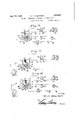
- Figure 1 is a sectional view taken on the line 11 of Fig. 2 and showing the parts in front elevation in full lines in normal position and in dotted lines in operative position to open the ignition circuit,
- Fig. 2 is an end elevation of the switch with the cover removed
- Fig. 3 is a rear elevation of the device
- Fig. 4 is a detail perspective view of the pivoted armature and dog
- Fig. 5 is a fragmentary sectional view showing the push rod and controlling spring
- Fig. 6 is a diagrammatic View of the switch applied to a battery, coil and distributer ignition system
- Fig. 7 is a diagrammatic view showing the switch and hook-up for a magneto ignition apparatus.
- Fig. 8 is a diagrammatic view showing the switch and hooks-up for a dual ignition apparatus including both magneto and battery, coil and distributer.
- the magnetic ignition switch is shown to comprise a base 10 7 preferably formed of insulating material, such as bakelite or the like, upon which is mounted, near the top thereof, an angle iron bracket 11.
- An electro-magnet 12 is secured to the underneath face of the bracket by means of a bolt 13 which also secures an angle iron bracket 14 to the bracket 11, which bracket 14 forms a mounting for the hereinafter described push rod and shaft of the ignition switch.
- a combined armature and dog is pivoted on the base 10 below the electro-magnet and comprises a dog 15 and an armature 16, which latter projects laterally from the dog to extend underneath the core 17 of the electro-magnet, as best shown in Fig. 2.
- the dog is preferably pivoted to the base by means of a bolt 18, and a substantially V-shaped spring 19 is looped over the bolt, one of the terminals of the spring being hooked over the dog, and the other terminal being hooked over an attaching screw 20, as best shown in Fig. 1, to normally hold the dog pressed downwardly to engage the pivoted switch segment, as will now be described.
- the pivoted switch segment 21 is preferably formed of insulating material, such as bakelite or the like, and is of the general shape shown in Fig. 1.
- the upper edge of the segment is notched, as shown at 22, to receive the dog 15.
- the lower end of the segment is keyed or otherwise rigidly secured to a rock shaft 23 which, as shown in Fig. 2, is journaled at one end in a suitable opening in the base 10 and, at the opposite end, projects through a suitable open ing in the above-mentioned front angle iron bracket 14.
- An ignition switch handle 24 is fixed to the projecting end of the rock shaft for manually turning the shaft clockwise.
- a spiral spring 25 encircles the shaft in front of the segment 21, one end of the spring being rigidly secured to the shaft in any preferred manner, and the opposite end being hooked over a pin 26 carried by the base plate.
- the switch points are mounted, as usual, on the pivoted segment 21 and, as best shown in Fig. 2, comprise a pair of arcuate copper or other metal arms 27 and 28 which are riveted or otherwise fixed at the inner ends upon the segment and extend from opposite sides of the segment.
- the arm 27 is provided with spaced fingers 29 and 30 which are bent obliquely toward the base 10 and terminate in disks 31 and 32 which have wiping contact with corresponding fixed switch contacts 33 and 34 on the base 10 and which are connected, as will be hereinafter more fully described, by corresponding conductor wires 35 and 36 preferably to the ammeter and to the high tension coil.
- the arm 28 is provided with fingers 37 and 38 which terminate in disks 39 and 40, respectively, which have wiping contact with respective stationary switch contacts 41 and 42, carried by the base 10, when the segment 21 is moved by the controlling spring 25 thereof counter-clockwise to ground the magneto ignition apparatus, the stationary switch contacts 41 and 42 being connected by corresponding conductor wires 43 and 44 to the ground and to the magneto, respectively.
- the electro-magnet 12 The purpose of the electro-magnet 12 is to release the dog automatically and, to this end, the electro-magnet coil 48 has one terminal 49 thereof connected to the above-mentioned stationary or fixed switch contact which is in the battery circuit.
- the other terminal 50 of the coil is connected to a binding post 51 on the base 10 from which a wire 52 leads, as best shown in Figs. 6, 7 and 8, to the oil gage 53 and temperature gage 54.
- Each gage is provided with an insulated bindin post in the path of movement of the int icating hand 56 which is, of course, grounded.
- Said wire 52 is connected to said insulated binding posts by corresponding wires 57 and 58.
- the electro-magnet thereupon attracts the armature 16, thereby rocking the dog 15 on its pivot and dislodging it from the notch 22 in the segment 21.
- the segment is instantly rotated counter-clockwise by its controlling spring 21 to disengage the fingers 29 and 30 from the fixed contacts 33 and 34. which are in series circuit with the battery B and coil 59 through the wire 35 and the wire 36, see Fig. 6, so that the primary ignition circuit is broken by such movement of the pivoted segment 21.
- the primary purpose of the push rod 45 is to manually open the ignition circuit when ever desired, and, for this purpose, the push rod is equipped, as will be observed by referring to Fig. 2, with a knob 63 on its outer end.
- a leaf spring 60 as best shown in Fig. 5, is secured at one end to the back of the base 10 by means of a screw 61 and bears with its free end against the inner end of the push rod, which, as will be observed, projects through an opening in the base plate. The leaf spring thus holds the push rod at its outer limit of movement so that the cam surface 47 will be disposed normally out of engagement with the dog.
- an additional stationary contact 62 is provided in the path of movement of the finger 3% on the switch arm 27.
- This switch contact may be grounded when the switch is used in connection with Electro- Lock cable, so that the igniton circuit from the coil and distributer will be grounded through the fingers 29 and 34, being disposed in engagement with the fixed contact 3-1 and additional fixed contact 32 when the ignition switch segment 21 is in off positon, or at its extreme limit of movement in a counter-clockwise direction.
- a magnetic ignition switch including a pressure and heat gage controlled electro-magnet, a switch segment operably connected to the electro-magnet armature and electrically connected with the ignition devices, said segment being adapted to be instantly released by the magnet to open the circuit to the ignition devices upon a predetermined drop in oil pressure or predetermined rise in temperature of the cooling system, and means for releasing the segment independently of the magnet.
- a magnetic ignition switch including a pressure and heat gage controlled electro-magnet, a spring-pressed switch segment having contact fingers extending from opposite sides thereof, a series of stationary contacts adapted to be electrically connected with said ignition devices, an armature for the electro-magnet having a dog engaging said segment for holding the segment in on position, energizing of said electro-magnet by a predetermined drop in oil pressure or a predetermined rise in temperature actuating said magnet to dislodge said dog and release said segment to be moved by its controlling spring to off position to open the ignition circuit to said devices, and a manually operable push rod having a cam surface adapted to engage said dog and release the same from the segment independently of said magnet.
- An electro-inagnetic ignition switch for internal combustion motors including stationary switch contacts adapted to be connected in series with the primary ignition circuit of the ignition devices of the motor, an electro-magnet adapted to be connected in series with an insulated contact in the path of a grounded hand of an oil pressure gage of the motor and with one of said stationary contacts, a pivoted spring-controlled switch segment having a plurality of switch contacts adapted to engage with the stationary contacts and close the circuit to said ignition devices, a pivoted spring-pressed dog engaging said segment for normally holding the segment in on position, an armature carried by the dog and extending laterally therefrom over the core of said magnet and adapted to be attracted when the magnet is energized by the oil gage hand impinging against said insulated contact and dislodging the dog from the segment to permit the segment to be moved to off position by its controlling spring to disengage the segment contacts from the stationary contacts and open the ignition circuit, and a manually operable push rod between the segment and dog adapted to dislodge the dog from the segment independently of the armature
- An electro-magnetic ignition switch for internal combustion motors including stationary switch contacts adapted to be connected in series with the primary ignition circuit of the ignition devices of the motor, an electro-magnet adapted to be connected in series with an insulated contact in the path of a ground hand of a heat gage of the motor cooling system and with one of said stationary contacts, a pivoted spring-controlled switch segment having a plurality of switch contacts adapted to engage with and electrically connect the stationary contacts and close the circuit to said ignition devices, a pivoted springpressed dog engaging in a notch in said segment for normally holding the segment in on position, an armature integral with the dog and extending laterally therefrom over the core ofsaid magnet and adapted to be attracted when the magnet is energized by the heat gage hand impinging against said insulated contact and dislodging the dog from the segment to permit the segment to be moved to off position by its controlling spring to disengage the segment contacts from the stationary contacts and open the ignition circuit, and a manually operable push rod between the segment and dog adapted to dislod
- a magneto and battery ignition devices a series of fixed switch contacts adapted to be electrically connected in circuit with said magneto and devices, a switch segment having switch contacts adapted to engage with and electrically connect certain of said fixed contacts, a pivoted dog adapted to engage the segment and hold the segment in on position, an armature carried by the dog, an electro-magnet adapted to be connected in series with one of said station-' ary contacts and with an msulated'contact 1n the path of movement of a grounded hand of a controlling gage of the motor, energizing of said magnet by contact of said hand with said insulated contact attracting the armature and dislodging the dog from the segment, a spring for returning the segment to oii position upon disengagement of the dog to open said ignition circuit and ground the magneto, and means for releasing the dog independently of the armature.
Landscapes
- Engineering & Computer Science (AREA)
- Mechanical Engineering (AREA)
- General Engineering & Computer Science (AREA)
- Physics & Mathematics (AREA)
- Fluid Mechanics (AREA)
- Chemical & Material Sciences (AREA)
- Combustion & Propulsion (AREA)
- Ignition Installations For Internal Combustion Engines (AREA)
Description
April 19, 1932. w ALBERTSON 1,854,571
OIL AND TEMPERATURE CONTROLLED IGNITION CUT-OUT Filed June 5, 1951 2 Sheets-Sheet 1 W E fizberzsan' P 1932- w. E. ALBERTSON 1,854,571
OIL AND TEMPERATURE CONTROLLED IGNITION CUT-OUT Filed June 5, 1931 I 2 Sheets-Sheet 2 OIL I 5 H5475 I? 10 atf a 48 i 2 f7 56' 6' 4a i 28 IL M $1 6' l I I -1 will Mz n v VV E Hiberis an Patented Apr. 19, 1932 UNITED STATES vvul U WILLIAM E. ALBER'I'SON, OF JACKSONVILLE, FLORIDA, ASSIGNOR OF ONE-HALF TO MAXEY D. MOODY, OF JACKSONVILLE, FLORIDA OIL AND TEMPERATURE CONTROLLED IGNITION OUT-OUT Application filed June 5, 1931.
This invention relates to oil and temperature controlled ignition cut-outs for automotive engines and has for an object to provide a magnetic ignition switch by means of which the ignition circuit will be automatically opened in the event of the oil pressure or level becoming so low, or the temperature of the cooling system becoming so high, as to endanger the bearings, cylinder walls, and other parts of the motor.
A further object is to provide a magnetic ignition switch including a pressure and heat gage operated electro-magnet, and a springpressed pivoted switch segment which is released by the magnet for instantly opening the ignition circuit upon a predetermined drop in oil pressure, or predetermined rise in temperature, the device being small, compact, inexpensive to manufacture, and being adapted to be located at any convenient place on the motor or vehicle.
A further object is to provide a magnetic ignition switch which may be used as the ignition switch on standard equipment. or may be used independently of or in connection with the standard ignition switch, and may be hooked up to control dual ignition including both magneto and distributor and coil ignition apparatus, or may be used alone to controleither magneto ignition apparatus or battery and coil ignition apparatus.
With the above and other objects in view the invention consists in certain novel details of construction and combinations of parts hereinafter fully described and claimed, it being understood that various modifications may be resorted to within the scope of the appended claims without departing from the spirit or sacrificing any of the advantages of the invention.
In the accompanying drawings forming part of this specification,
Figure 1 is a sectional view taken on the line 11 of Fig. 2 and showing the parts in front elevation in full lines in normal position and in dotted lines in operative position to open the ignition circuit,
Fig. 2 is an end elevation of the switch with the cover removed,
Fig. 3 is a rear elevation of the device,
Serial N0. 542,392.
showing the terminals and showing the spring for controlling the push rod,
Fig. 4 is a detail perspective view of the pivoted armature and dog,
Fig. 5 is a fragmentary sectional view showing the push rod and controlling spring,
Fig. 6 is a diagrammatic View of the switch applied to a battery, coil and distributer ignition system,
Fig. 7 is a diagrammatic view showing the switch and hook-up for a magneto ignition apparatus, and
Fig. 8 is a diagrammatic view showing the switch and hooks-up for a dual ignition apparatus including both magneto and battery, coil and distributer.
Referring now to the drawings in which like characters of reference designate similar parts in the various views, the magnetic ignition switch is shown to comprise a base 10 7 preferably formed of insulating material, such as bakelite or the like, upon which is mounted, near the top thereof, an angle iron bracket 11. An electro-magnet 12 is secured to the underneath face of the bracket by means of a bolt 13 which also secures an angle iron bracket 14 to the bracket 11, which bracket 14 forms a mounting for the hereinafter described push rod and shaft of the ignition switch.
A combined armature and dog, best shown in Fig. 4, is pivoted on the base 10 below the electro-magnet and comprises a dog 15 and an armature 16, which latter projects laterally from the dog to extend underneath the core 17 of the electro-magnet, as best shown in Fig. 2. The dog is preferably pivoted to the base by means of a bolt 18, and a substantially V-shaped spring 19 is looped over the bolt, one of the terminals of the spring being hooked over the dog, and the other terminal being hooked over an attaching screw 20, as best shown in Fig. 1, to normally hold the dog pressed downwardly to engage the pivoted switch segment, as will now be described.
The pivoted switch segment 21 is preferably formed of insulating material, such as bakelite or the like, and is of the general shape shown in Fig. 1.
The upper edge of the segment is notched, as shown at 22, to receive the dog 15. The lower end of the segment is keyed or otherwise rigidly secured to a rock shaft 23 which, as shown in Fig. 2, is journaled at one end in a suitable opening in the base 10 and, at the opposite end, projects through a suitable open ing in the above-mentioned front angle iron bracket 14. An ignition switch handle 24 is fixed to the projecting end of the rock shaft for manually turning the shaft clockwise. For automatically turning the shaft counter-clockwise, a spiral spring 25 encircles the shaft in front of the segment 21, one end of the spring being rigidly secured to the shaft in any preferred manner, and the opposite end being hooked over a pin 26 carried by the base plate.
The switch points are mounted, as usual, on the pivoted segment 21 and, as best shown in Fig. 2, comprise a pair of arcuate copper or other metal arms 27 and 28 which are riveted or otherwise fixed at the inner ends upon the segment and extend from opposite sides of the segment. The arm 27 is provided with spaced fingers 29 and 30 which are bent obliquely toward the base 10 and terminate in disks 31 and 32 which have wiping contact with corresponding fixed switch contacts 33 and 34 on the base 10 and which are connected, as will be hereinafter more fully described, by corresponding conductor wires 35 and 36 preferably to the ammeter and to the high tension coil.
Likewise, the arm 28 is provided with fingers 37 and 38 which terminate in disks 39 and 40, respectively, which have wiping contact with respective stationary switch contacts 41 and 42, carried by the base 10, when the segment 21 is moved by the controlling spring 25 thereof counter-clockwise to ground the magneto ignition apparatus, the stationary switch contacts 41 and 42 being connected by corresponding conductor wires 43 and 44 to the ground and to the magneto, respectively.
It is now clear that when the pivoted switch segment 21 is manually turned clockwise by means of the ignition switch handle 24, the dog 15 will lod e in the notch 22, as shown in Fig. 1, and hold the segment in this position. For the purpose of manually releasing the dog when necessary, a push rod 45, as best shown in Figs. 2 and 5, is slidably and non-rotatably fitted in openings in the base 10 and front angle iron bracket 14 and is equipped on the upper side with a tooth 46 having an inclined cam surface 47 on the rear edge which, when the push rod is moved inwardly, rides upon the underneath edge of the dog 15 and rocks the dog upwardly against the tension of its controlling spring 19 to dislodge the dog from the notch 22 and permit the spring-pressed pivoted segment 21 being instantly moved in a counter-clockwise direction by its controlling spiral spring 25.
The purpose of the electro-magnet 12 is to release the dog automatically and, to this end, the electro-magnet coil 48 has one terminal 49 thereof connected to the above-mentioned stationary or fixed switch contact which is in the battery circuit. The other terminal 50 of the coil is connected to a binding post 51 on the base 10 from which a wire 52 leads, as best shown in Figs. 6, 7 and 8, to the oil gage 53 and temperature gage 54.
Each gage is provided with an insulated bindin post in the path of movement of the int icating hand 56 which is, of course, grounded. Said wire 52 is connected to said insulated binding posts by corresponding wires 57 and 58.
It will be now clear that in the event of the oil pressure or level dropping dangerously low, for example to two or three pounds, or in the event of the temperature of the cooling system rising dangerously high, a circuit may be traced from the storage battery B, see Fig. 6, through the wire 35, finger 29, arm 27, finger 30, wire 49, coil 48 of the electro-magnet, and through the wire 52 to the grounded hand of the oil or temperature gage, so that the electro-magnet is energized.
The electro-magnet thereupon attracts the armature 16, thereby rocking the dog 15 on its pivot and dislodging it from the notch 22 in the segment 21. The segment is instantly rotated counter-clockwise by its controlling spring 21 to disengage the fingers 29 and 30 from the fixed contacts 33 and 34. which are in series circuit with the battery B and coil 59 through the wire 35 and the wire 36, see Fig. 6, so that the primary ignition circuit is broken by such movement of the pivoted segment 21.
Simultaneously with the opening of the battery circuit, where a dual ignition hookup including a magneto is also employed, as shown in Fig. 8, the movement of the segment by its spiral controlling spring moves the fingers 37 and 38 into contact with the stationary switch contacts 41 and 42 to ground the magneto, since in such position of the parts a circuit may be traced from the ground terminal of the magneto through the wire 44, stationary contact 42, fingers 38 and 37, sta tionary contact 41 and ground wire 43.
In the diagrammatic view shown in Fi". 7 the switch as shown employed in connection with magneto ignition only, and, in this connection, it will be observed that the usual ignition storage battery is dispensed with and, in lieu thereof, a small battery, such as the single cell Hot Shot battery, marked B, may be connected to the battery terminal 33 for cooperation with the electro-magnet coil which, in this instance, acts in the same manner as above described in detail, as will be understood.
The primary purpose of the push rod 45 is to manually open the ignition circuit when ever desired, and, for this purpose, the push rod is equipped, as will be observed by referring to Fig. 2, with a knob 63 on its outer end. A leaf spring 60. as best shown in Fig. 5, is secured at one end to the back of the base 10 by means of a screw 61 and bears with its free end against the inner end of the push rod, which, as will be observed, projects through an opening in the base plate. The leaf spring thus holds the push rod at its outer limit of movement so that the cam surface 47 will be disposed normally out of engagement with the dog. It is clear, however, that, by simply pushing in on the knob 63, the cam surface will be brought into enga ement with the dog, as above described, and the dog will be lifted and dislodged from the notch 22 in the pivoted switch segment 21 to permit the latter being moved by its controlling spring to open the ignition circuit, as above described.
It will be observed that when the ignition switch is initially turned to close the primary ignition circuit, when the motor is cold at starting, the grounded hand of the oil gage will be in engagement with its contact 55, so that the electro-magnet will be energized and will automatically open the ignition circuit. In order to counteract the effect of the electromagnet when starting, it is, therefore, necessary to manually hold the ignition switch handle 24: stationary so that the ignition circuit from the battery through the coil and distributer will be maintained closed until the motor starts, even though the parallel electric circuit through the gages and through the electro-magnet is grounded at the oil gage.
By referring to Figs. 1 and 3, it will be observed that an additional stationary contact 62 is provided in the path of movement of the finger 3% on the switch arm 27. This switch contact may be grounded when the switch is used in connection with Electro- Lock cable, so that the igniton circuit from the coil and distributer will be grounded through the fingers 29 and 34, being disposed in engagement with the fixed contact 3-1 and additional fixed contact 32 when the ignition switch segment 21 is in off positon, or at its extreme limit of movement in a counter-clockwise direction.
It is thought that, from the above descrip tion, the construction and operation of my invention will be thoroughly understood with out further explanation.
Having thus described the invention, I claim:
1. The combination with the ignition devices of an internal combustion motor and the cooling and pressure lubrication system thereof, of a magnetic ignition switch including a pressure and heat gage controlled electro-magnet, a switch segment operably connected to the electro-magnet armature and electrically connected with the ignition devices, said segment being adapted to be instantly released by the magnet to open the circuit to the ignition devices upon a predetermined drop in oil pressure or predetermined rise in temperature of the cooling system, and means for releasing the segment independently of the magnet.
2. The combination with the ignition devices of an internal combustion motor and the cooling and pressure lubrication system thereof, of a magnetic ignition switch including a pressure and heat gage controlled electro-magnet, a spring-pressed switch segment having contact fingers extending from opposite sides thereof, a series of stationary contacts adapted to be electrically connected with said ignition devices, an armature for the electro-magnet having a dog engaging said segment for holding the segment in on position, energizing of said electro-magnet by a predetermined drop in oil pressure or a predetermined rise in temperature actuating said magnet to dislodge said dog and release said segment to be moved by its controlling spring to off position to open the ignition circuit to said devices, and a manually operable push rod having a cam surface adapted to engage said dog and release the same from the segment independently of said magnet.
3. An electro-inagnetic ignition switch for internal combustion motors including stationary switch contacts adapted to be connected in series with the primary ignition circuit of the ignition devices of the motor, an electro-magnet adapted to be connected in series with an insulated contact in the path of a grounded hand of an oil pressure gage of the motor and with one of said stationary contacts, a pivoted spring-controlled switch segment having a plurality of switch contacts adapted to engage with the stationary contacts and close the circuit to said ignition devices, a pivoted spring-pressed dog engaging said segment for normally holding the segment in on position, an armature carried by the dog and extending laterally therefrom over the core of said magnet and adapted to be attracted when the magnet is energized by the oil gage hand impinging against said insulated contact and dislodging the dog from the segment to permit the segment to be moved to off position by its controlling spring to disengage the segment contacts from the stationary contacts and open the ignition circuit, and a manually operable push rod between the segment and dog adapted to dislodge the dog from the segment independently of the armature.
4. An electro-magnetic ignition switch for internal combustion motors including stationary switch contacts adapted to be connected in series with the primary ignition circuit of the ignition devices of the motor, an electro-magnet adapted to be connected in series with an insulated contact in the path of a ground hand of a heat gage of the motor cooling system and with one of said stationary contacts, a pivoted spring-controlled switch segment having a plurality of switch contacts adapted to engage with and electrically connect the stationary contacts and close the circuit to said ignition devices, a pivoted springpressed dog engaging in a notch in said segment for normally holding the segment in on position, an armature integral with the dog and extending laterally therefrom over the core ofsaid magnet and adapted to be attracted when the magnet is energized by the heat gage hand impinging against said insulated contact and dislodging the dog from the segment to permit the segment to be moved to off position by its controlling spring to disengage the segment contacts from the stationary contacts and open the ignition circuit, and a manually operable push rod between the segment and dog adapted to dislodge the dog from the segment independently of the armature.
5. In a dual ignition system for internal combustion motors, a magneto and battery ignition devices, a series of fixed switch contacts adapted to be electrically connected in circuit with said magneto and devices, a switch segment having switch contacts adapted to engage with and electrically connect certain of said fixed contacts, a pivoted dog adapted to engage the segment and hold the segment in on position, an armature carried by the dog, an electro-magnet adapted to be connected in series with one of said station-' ary contacts and with an msulated'contact 1n the path of movement of a grounded hand of a controlling gage of the motor, energizing of said magnet by contact of said hand with said insulated contact attracting the armature and dislodging the dog from the segment, a spring for returning the segment to oii position upon disengagement of the dog to open said ignition circuit and ground the magneto, and means for releasing the dog independently of the armature.
In testimony whereof I aifix my signature.
lVILLIAM E. ALBERTSON.
Publications (1)
| Publication Number | Publication Date |
|---|---|
| US1854571A true US1854571A (en) | 1932-04-19 |
Family
ID=3423675
Family Applications (1)
| Application Number | Title | Priority Date | Filing Date |
|---|---|---|---|
| US1854571D Expired - Lifetime US1854571A (en) | Oil and temperature controlled ignition cttt-otjt |
Country Status (1)
| Country | Link |
|---|---|
| US (1) | US1854571A (en) |
Cited By (8)
| Publication number | Priority date | Publication date | Assignee | Title |
|---|---|---|---|---|
| US2467333A (en) * | 1947-08-18 | 1949-04-12 | Frank W Murphy | Automatic safety ignition switch |
| US2562286A (en) * | 1948-12-03 | 1951-07-31 | Oswald H Milmore | Temperature and pressure responsive switch |
| US2565984A (en) * | 1951-08-28 | Ignition control | ||
| US3278803A (en) * | 1966-10-11 | Rectifying system for protecting inter- nal combustion engines having plural magnetos | ||
| US3659113A (en) * | 1970-05-25 | 1972-04-25 | Caterpillar Tractor Co | Engine start and shutdown system |
| US3746926A (en) * | 1972-09-20 | 1973-07-17 | Murphy F Manufacturer Inc | Safety system incorporating a plurality of control switches |
| US3760781A (en) * | 1971-03-26 | 1973-09-25 | G Boldt | Engine safety system having safety assembly indentifiably operable for each combustion chamber |
| US5501294A (en) * | 1994-12-27 | 1996-03-26 | Chih-Chun; Lo | Brake oil level safety device for motor vehicles |
-
0
- US US1854571D patent/US1854571A/en not_active Expired - Lifetime
Cited By (8)
| Publication number | Priority date | Publication date | Assignee | Title |
|---|---|---|---|---|
| US2565984A (en) * | 1951-08-28 | Ignition control | ||
| US3278803A (en) * | 1966-10-11 | Rectifying system for protecting inter- nal combustion engines having plural magnetos | ||
| US2467333A (en) * | 1947-08-18 | 1949-04-12 | Frank W Murphy | Automatic safety ignition switch |
| US2562286A (en) * | 1948-12-03 | 1951-07-31 | Oswald H Milmore | Temperature and pressure responsive switch |
| US3659113A (en) * | 1970-05-25 | 1972-04-25 | Caterpillar Tractor Co | Engine start and shutdown system |
| US3760781A (en) * | 1971-03-26 | 1973-09-25 | G Boldt | Engine safety system having safety assembly indentifiably operable for each combustion chamber |
| US3746926A (en) * | 1972-09-20 | 1973-07-17 | Murphy F Manufacturer Inc | Safety system incorporating a plurality of control switches |
| US5501294A (en) * | 1994-12-27 | 1996-03-26 | Chih-Chun; Lo | Brake oil level safety device for motor vehicles |
Similar Documents
| Publication | Publication Date | Title |
|---|---|---|
| US1854571A (en) | Oil and temperature controlled ignition cttt-otjt | |
| US2033252A (en) | Ignition starter control | |
| US1854166A (en) | Magnetic ignition switch | |
| US3424950A (en) | Magnetic make and break igniter | |
| US2584907A (en) | Distributor | |
| US1498818A (en) | Electric switch for automobile starters | |
| US1451157A (en) | Circuit breaker | |
| US2992303A (en) | murphy | |
| US1903761A (en) | Automatic electric starter for internal combustion engines | |
| US2364143A (en) | Vehicle signal control unit | |
| US3815061A (en) | Automatic control cable assembly | |
| US1948198A (en) | Automatic starter for internal combustion engines | |
| US1942115A (en) | Automobile appliance | |
| US808957A (en) | Circuit-controller. | |
| US2490013A (en) | Electrical switch | |
| US1710884A (en) | Switch | |
| US1985309A (en) | Automatic starter | |
| US2552141A (en) | Electrical switch | |
| US1899000A (en) | Electric switch | |
| US2253142A (en) | Relay | |
| US1665562A (en) | Starter for electric mctors | |
| US1977230A (en) | Means for locating engine troubles | |
| US2249893A (en) | Automatic ignition circuit breaker | |
| US2448897A (en) | Surge generator | |
| US1534379A (en) | Contact breaker |