US1854569A - Air conditioning device - Google Patents
Air conditioning device Download PDFInfo
- Publication number
- US1854569A US1854569A US488115A US48811530A US1854569A US 1854569 A US1854569 A US 1854569A US 488115 A US488115 A US 488115A US 48811530 A US48811530 A US 48811530A US 1854569 A US1854569 A US 1854569A
- Authority
- US
- United States
- Prior art keywords
- air
- liquid
- filter
- compartment
- casing
- Prior art date
- Legal status (The legal status is an assumption and is not a legal conclusion. Google has not performed a legal analysis and makes no representation as to the accuracy of the status listed.)
- Expired - Lifetime
Links
- 238000004378 air conditioning Methods 0.000 title description 15
- 239000007788 liquid Substances 0.000 description 35
- 238000005192 partition Methods 0.000 description 15
- XLYOFNOQVPJJNP-UHFFFAOYSA-N water Substances O XLYOFNOQVPJJNP-UHFFFAOYSA-N 0.000 description 12
- 239000007921 spray Substances 0.000 description 8
- 238000010438 heat treatment Methods 0.000 description 7
- 238000001816 cooling Methods 0.000 description 5
- 238000001704 evaporation Methods 0.000 description 4
- 239000000463 material Substances 0.000 description 4
- 239000003595 mist Substances 0.000 description 4
- 230000008020 evaporation Effects 0.000 description 3
- 238000001914 filtration Methods 0.000 description 3
- 239000006193 liquid solution Substances 0.000 description 3
- 238000010276 construction Methods 0.000 description 2
- 239000004744 fabric Substances 0.000 description 2
- 239000002245 particle Substances 0.000 description 2
- 229920006395 saturated elastomer Polymers 0.000 description 2
- 235000014653 Carica parviflora Nutrition 0.000 description 1
- 241000243321 Cnidaria Species 0.000 description 1
- 229920000742 Cotton Polymers 0.000 description 1
- 238000000889 atomisation Methods 0.000 description 1
- 239000000428 dust Substances 0.000 description 1
- 238000013467 fragmentation Methods 0.000 description 1
- 238000006062 fragmentation reaction Methods 0.000 description 1
- 238000007689 inspection Methods 0.000 description 1
- 238000005406 washing Methods 0.000 description 1
Images

Classifications
-
- F—MECHANICAL ENGINEERING; LIGHTING; HEATING; WEAPONS; BLASTING
- F24—HEATING; RANGES; VENTILATING
- F24F—AIR-CONDITIONING; AIR-HUMIDIFICATION; VENTILATION; USE OF AIR CURRENTS FOR SCREENING
- F24F3/00—Air-conditioning systems in which conditioned primary air is supplied from one or more central stations to distributing units in the rooms or spaces where it may receive secondary treatment; Apparatus specially designed for such systems
- F24F3/12—Air-conditioning systems in which conditioned primary air is supplied from one or more central stations to distributing units in the rooms or spaces where it may receive secondary treatment; Apparatus specially designed for such systems characterised by the treatment of the air otherwise than by heating and cooling
-
- Y—GENERAL TAGGING OF NEW TECHNOLOGICAL DEVELOPMENTS; GENERAL TAGGING OF CROSS-SECTIONAL TECHNOLOGIES SPANNING OVER SEVERAL SECTIONS OF THE IPC; TECHNICAL SUBJECTS COVERED BY FORMER USPC CROSS-REFERENCE ART COLLECTIONS [XRACs] AND DIGESTS
- Y10—TECHNICAL SUBJECTS COVERED BY FORMER USPC
- Y10S—TECHNICAL SUBJECTS COVERED BY FORMER USPC CROSS-REFERENCE ART COLLECTIONS [XRACs] AND DIGESTS
- Y10S261/00—Gas and liquid contact apparatus
- Y10S261/34—Automatic humidity regulation
-
- Y—GENERAL TAGGING OF NEW TECHNOLOGICAL DEVELOPMENTS; GENERAL TAGGING OF CROSS-SECTIONAL TECHNOLOGIES SPANNING OVER SEVERAL SECTIONS OF THE IPC; TECHNICAL SUBJECTS COVERED BY FORMER USPC CROSS-REFERENCE ART COLLECTIONS [XRACs] AND DIGESTS
- Y10—TECHNICAL SUBJECTS COVERED BY FORMER USPC
- Y10S—TECHNICAL SUBJECTS COVERED BY FORMER USPC CROSS-REFERENCE ART COLLECTIONS [XRACs] AND DIGESTS
- Y10S55/00—Gas separation
- Y10S55/31—Filter frame
Definitions
- Figure 5 is a perspectiveview of the supporting member for the impingement screens.
- Figure 6 is a perspective view of one of the compact, eliicient and Another object consists in providing a conimpingement screens with parts cut away for clearness of illustration.
- the casing 10 is divided by the partition 16 into an air receiving compartment 17 and a filter compartment 18 whlch communicate with each other through an annular opening 19 in the partition 16.
- the outer end 20 of the casing is preferably detachably secured in position by the bolts 20' and has a central screened air inlet opening 21 for conducting the air to be treated into the casing.
- the diffuser housing 42 is arranged to receive a series of downwardly inclined uniformly spaced screens.
- these screens may assume various other angular positions in order to collect the liquid and insure the air as it passes through the member 42 being thoroughly filtered.
- the vanes or screens 50 are so shaped as to provide at their lower converging sides a basin in which the water or liquid collects.
- the water thus collected is blown toward the fiutlet end 31 of the casing, so that the screens are constantly saturated.
- An air conditioning device comprising a casing having opposed air inlet and outlet passages, a partition having a medially disposed opening separating the easing into an air receiving compartment and a filter compartment, a motor mounted in said air comapartment and having a drive shaft extending in opposite directions towards said inlet and outlet passages, an impeller connected to one end of said shaft for circulating the air through said casing, the opposite end of said shaft extending through said opening into the filter compartment and having a dasher connected thereto, means for maintaining liquid in said filter compartment at a predetermined level, an impingement screen p0 sitioned between said dasher and the outlet passage for treating the air as it passes through the filter compartment, said dasher extending into the liquid to provide, when the shaft is actuated a thin spray or film through which the air passes, and means for directing the moist air to the impingement screen for purifying the same prior toits delivery to the outlet passage.
- An air conditioning device comprising a casing having opposed inlet and outlet openings, a partition separating the easing into an air receiving compartment and a filter compartment, means for circulating air through said casing, said filter compartment having liquid in the bottom thereof, means for maintaining the liquid at a predetermined level, a dasher extending into said liquid, a shield encircling said dasher and connected to said partition, a diffuser housing detachably mounted on said shield for receiving and atomizing the liquid so as to form a spray through which the air passes, angularly disposed filter vanes mounted in said housing over which the moist air circulates, means for constantly maintaining said vanes saturated, said vanes being composed of material that causes evaporation of the liquid when the 'moist air passes thereover.
Landscapes
- Engineering & Computer Science (AREA)
- Chemical & Material Sciences (AREA)
- Combustion & Propulsion (AREA)
- Mechanical Engineering (AREA)
- General Engineering & Computer Science (AREA)
- Filtering Of Dispersed Particles In Gases (AREA)
Description
April 19, 1932. I p B, w cH 1,854,569
AIR CONDITIONING DEVICE Filed Oct. 11, 1930 2 Sheets-Sheet l gwuentov 1 00/ 5 fiiC/L it W April1, 1932. P, B WELCH 1,854,569
AIR CONDITIONING DEVICE Filed Oct. 11,'l930 2 Sheets-Sheet 2 Patented Apr. 19, 1932 PAUL BROWN WELCH, OI CORAL GABLES, FLORIDA AIR CONDITIONING DEVICE Application filed October 11, 1930. Serial No. 488,115.
The present invention relates to an air conditioning apparatus or unit and more particularly to improved means for treating air delivered into abuilding, room or the like.
The primary object of the invention is to provide a simple, economical air conditioning apparatus which is arranged to receive the outside or impure air and subject the same to a dry filter to remove heavy particles of dirt or other foreign matter entrained with the air. The air is then directed through a fine spray or mist of water so as to Wash the same and the moist air as it issues from the bath is conducted through filter vanes or impingement screens so as to collect the liquid and purify the air before it is delivered into the building or room in which the apparatus is installed.
A further object comprehends the provision of a portable air conditioning device which may be readily installed wherever it is desired to provide fresh pure air. Additionally, means are provided for heating or cooling the air as it circulates through the apparatus.
ditioning apparatus in which the various parts are detachably' mounted in position so that theymay be removed for the purpose of inspection or repair.
Other objects and advantages of the invention will become apparent from the following description when taken in conjunction with the accompanying claims.
Referring to the drawings in which are shown several preferred embodiments of the invention:
Figure 1 is a perspective view showing the invention mounted in the window of a'building or the like.
Figure 2 is an enlarged vertical sectional view of the invention.
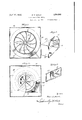
Figure 3 is a sectional view taken substantially along the line 33 of Figure 2.
Figure 4 is a sectional view taken substantially along the line H of Figure 2.
Figure 5 is a perspectiveview of the supporting member for the impingement screens. 59 Figure 6 is a perspective view of one of the compact, eliicient and Another object consists in providing a conimpingement screens with parts cut away for clearness of illustration.
Figure 7 is a. sectional view of a modified form of screen supporting member.
Referring to the drawings in which like numerals indicate like parts in the several views, 10 designates the air conditioning apparatus or casing, which as shown in Figure l is arranged to be detachably secured to one side of a window frame 11 through the instrumentality of a top flange 12 that en ages the outer side of the window 13 when t e apparatus is mounted in the opening between the window and the sill 14. A movable closure member 15, slidably connected to the casing 05 10, is preferably provided to close the opening between the apparatus and the opposite side of the window frame so as to insure the admission of filtered air only into the room in which the apparatus is installed.
The casing 10 is divided by the partition 16 into an air receiving compartment 17 and a filter compartment 18 whlch communicate with each other through an annular opening 19 in the partition 16. The outer end 20 of the casing is preferably detachably secured in position by the bolts 20' and has a central screened air inlet opening 21 for conducting the air to be treated into the casing.
A tubular pipe or conduit 22 is connected to p the end'20 of the casing and is provided with a depending portion for receiving the atmospheric or impure air and conducting it to the casing. In order to remove any large particles of dirt or other foreign matter which might be'entrained with the air delivered to the compartment 17, there is preferably, removably mounted in the pipe 22, a dry filter screen 23, that may be formed of any suitable fabric sovas to subject the'air to a preliminary treatment prior to its introduction into the casin The flow into the compartment 18 may e controlled by a valve 23' mounted in the lower portion of the ipe 22.
A motor 24 is prefera 1y mounted in the air receiving compartment 17 on a stand 25 that is secured to the bottom of the casing by the bolts 26. The drive'shaft 27 of the motor extends longitudinally in opposite directions and has keyed or otherwise secured to its outer end, an impeller or fan 28 which may be formed with the radially curved blades 29 (Figure 3) that are closely positioned ad acent the inlet opening 21 of the casing and are provided with concave portions 30 that constitute a chamber or space adjacent the hub of the impeller for receiving the incoming air. It will be seen that upon the actuation of the impeller, the air is drawn in through the conduit 20 and circulated through the easing 10 and escapes through the outlet openings 31 in the inner side 32 of the casing. In order to direct the flow of the current of air throu h the compartment 17, a conically shape deflector blade 33 is connected to the inner side of the removable end 20 of the casing and surrounds the impeller 28 so as to cause the air to circulate in the manner as indicated by the arrows in Figure 2.
The filter compartment 18 is provided with a movable top 34 hinged at 35 so as to permit access into the interior thereof. The inner end of the drive shaft 27 extends through the opening 19 in the partition 16, and has keyed or otherwise secured thereto, a dasher 36 which preferably is composed of an annument 18. The radial arms 38 are each provided with convex reduced portions 40 formed adjacent the opening 19 in the partition 16 so that the flow of the air as it strikes the disc 37 will not be impeded in escaping outwardly from the dasher.
A conically shaped hood or shield 41 is connected to the wall of the partition 16 and extends outwardly into the compartment 18 to act as a deflector plate or baflle for the air as it issues into the compartment 18. The shield 41 also acts as a support for a filter member or diffuser housing 42 in which is removably mounted the impingement screens or filter vanes.
As shown in Figure 5 of the drawings, the member 42 preferably comprises a rectangular body 43 having a semi-circular hood 44 which is formed with a downwardly extending flange 45 arranged to be detachably mounted on the adjacent surface of the shield 41. The opposed sides of the member 42 are provided with a series of aligned brackets 46 which support the frames 47 on which are remo'vably positioned the filter vanes 48 which vanes are preferably formed of any suitable good grade of fabric such as white cotton flannel or the like, so that these vanes or screens may be conveniently removed to be cleaned or a new set attached to the frames.
As shown in Figures 2 and 5, the diffuser housing 42 is arranged to receive a series of downwardly inclined uniformly spaced screens. However, these screens may assume various other angular positions in order to collect the liquid and insure the air as it passes through the member 42 being thoroughly filtered.
As shown in Figure 7, the member 49 is substantially the same in construction as the member 42 previously described with the exception that the implngement screens 50 are provided with uniformly spaced downwardly and upwardly extending portions over which the moist air circulates prior to its delivery to the outlet openings 31.
The filter vanes 0r impingement screens 48 and 50 are formed of such material as to provide an evaporating surface over which the moist air passes, so that the liquid upon being absorb-ed or evaporated produces a drop in temperature of the air of from 4 to 10 F as it passes through the apparatus.
The dasher 36 extends a limited distance into water or any other liquid solution 51 in the bottom ofthe filter com )artment 18, so that upon rotation of the sha t 27, the dasher throws the Water upwardly into the chamber formed by the flange 41 and the diffuser housing 42 to provide a thin spray or mist through which the air passes. The moist air is then conducted through the impingement screens 48 which collect the water or liquid and removes any dust or other foreign matter that may be entrained therewith, so that the air is fresh, pure and filtered as it leaves the openings 31.
A removable reservoir 52 positioned in the upper portion of the compartment 19 has a depending supply pipe 53 which extends down into the liquid 51 a limited distance to insure the liquid remaining at a constant level within the compartment 18.
In order that the temperature of the air issuing from the apparatus may be changed as conditions warrant, a series of cooling or heating coils 54 may be mounted in the tank 52 and in the bottom of the filter compartment 18, as well as in front of the filter member 42 so that these coils may be connected to either a heating unit or a refrigerating unit, not shown, in order that the air as it issues from the apparatus will be either warm or cool as desired. Additionally, a heating or cooling coil 54 may be positioned in the compartment 17, so that the temperature of the air may be varied before it is delivered to the filter compartment 18; this is particularly desirable in cool weather where the heating unit is connected to the coils, since it increases the humidity of the air issuing from the outlet openings 31.
As the major portion of the conditiomng device extends within the room or building to which it is installed, means are provided for supporting the apparatus on the inside of the window, which means preferably comprises an arm 55 pivoted at 56 to the bottom of the casing 10 and limited in its downward movement by a link 57 which is also connected as at 58 to the bottom of the apparatus. The free end of the arm 55 is arranged to abut against the sill 14 of the window so asto coact with the flange 12 to insure the apparatus being properly held in a fixed position.
In operation, the motor 24 which may be suitably connected to the house current, is turned on, and the impeller 28 and dasher 36 are rotated in the same direction, thus causing the air to be drawn into and circulated through the casing. As the air reaches the filter chamber, it is subjected to a washing operation prior to being dried and purified by its passage through the impingement screens 48 in the filter member 42. The liquid employed may be either water or any other special solution which has been found desirable for use in devices of this character.
An increase in velocity is imparted to the air as it passes through the compartment 17 by the impeller 28 while the speed of the dasher 38 throws the water or liquid in the bottom of the compartment 18 outwardly against the diffuser housing 42 with such force that the liquid is completely broken up. As the air passes through this fragmented water, it causes an atomization that produces a thin spray or mist which is conducted over the filter vanes.
In the form of the invention illustrated in Figure 7, the vanes or screens 50 are so shaped as to provide at their lower converging sides a basin in which the water or liquid collects. The water thus collected is blown toward the fiutlet end 31 of the casing, so that the screens are constantly saturated. By reason of this construction, it will be seen that the jetting of the air and fragmentation of the water eliminates the use of a high pressure jet and outside water supply such as pumps and the like. which heretoforehave been required.
When the device is used for purifying or filtering the air in cold weather the coils 54 and 54' may be connected to an electrical heating unit or the like so as to increase the temperature of the air either before it passes through the diifuser housing 42 or the water may be heated so as to raise the temperature of the air as it is subjected to the filtering operation, thus increasing the humidity of the air as it issues from the apparatus. On the other hand, in warm weather, the coils 54 and 54 may be connected to a cooling unit so as to lower the relative humidity of the air, the drop in humidity being proportionate to the drop in temperature. It will be understood, of course, that any one or all of the heating or cooling coils shown may be used as conditions warrant.
It will be noted that the filter member 42 and reservoir 52 may be conveniently removed from the casin while the filter screens are so mounted on their frames that when they become dirty or need to be renewed or repaired, this may be done at a minimum exinvention herewith shown and described are merely illustrative of preferred embodiments and that such changes may be made as fall within the purview of one skilled in the art without departing from the spirit of the invention and the scope of the appended claims.
I claim:
1. An air conditioning device comprising a casing having opposed air inlet and outlet passages, a partition separating the easing into an air receiving compartment and a filter compartment, means for forcing the air through said casing, a liquid solution in the bottom of said filter compartment, means for maintaining said solution at a predetermined level, a dasher extending into said liquid solution for providing a thin sheet or film through which the air passes, said partition having an outwardly projecting flange extending into the filter compartment and surrounding the dasher, a supporting member detachably connected to said flange and provided with angularly disposed impingement screens for treating the moist air as it passes through the filter compartment, said flange and supporting member constituting a closed chamber for confining and controlling the direction of the air passing through the casmg.
2. An air conditioning device comprising a casing having opposed air inlet and outlet passages, means for preliminarily treating the air as it passes through said inlet passage, passage, a partition separating the casing 1nto an air receiving compartment and a filter compartment, a motor mounted in said air receiving compartment and having a drive shaft extending in opposite directions towards the air inlet and the outlet passages, an impeller connected to one end of said shaft for forcing the air into and through the easing, a deflector surrounding said impeller for controlling the flow of air intothe receiving compartment, the opposite end of said shaft extending into said filter compartment, and having a disc connected thereto, plates extending radially from the hub of said disc and providing passages for conducting the air into the filter compartment, said partition having a flange extending into said filter or sheet and is then conducted through the filter vanes to be purified 'before delivery to the outlet passage.
3. An air conditioning device comprising a casing having opposed air inlet and outlet passages, a partition having a medially disposed opening separating the easing into an air receiving compartment and a filter compartment, a motor mounted in said air comapartment and having a drive shaft extending in opposite directions towards said inlet and outlet passages, an impeller connected to one end of said shaft for circulating the air through said casing, the opposite end of said shaft extending through said opening into the filter compartment and having a dasher connected thereto, means for maintaining liquid in said filter compartment at a predetermined level, an impingement screen p0 sitioned between said dasher and the outlet passage for treating the air as it passes through the filter compartment, said dasher extending into the liquid to provide, when the shaft is actuated a thin spray or film through which the air passes, and means for directing the moist air to the impingement screen for purifying the same prior toits delivery to the outlet passage.
4. An air conditioning device comprising a casin g having opposed inlet and outlet openings, a partition separating the easing into an air receiving compartment and a filter compartment, means for circulating air through 'said casing, said filter compartment having liquid in the bottom thereof, means for maintaining the liquid at a predetermined level, a dasher extending into said liquid for forming a spray through which the air passes, a. supporting member mounted in said filter compartment, hollow frame members removably mounted in said supporting member, and a liquid in the bottom thereof, means for main 7 taining the liquid at a predetermined level, a dasher extending into said liquid for forming a spray through which the air passes, a diffuser housing mounted in said filter compartment for receiving and atomizing the liquid as it issues from the dasher, filter vanes in said housing over which the moist air passes onits way to the outlet opening, said vanes being composed of material which causes evaporation of the liquid and the filtering of the air prior to its delivery to the outlet opening.
6. An air conditioning device comprising a casing having opposed inlet and outlet openings, a partition separating the easing into an air receiving compartment and a filter compartment, means for circulating air through said casing, said filter compartment having liquid in the bottom thereof, means for maintaining the liquid at a predetermined level, a dasher extending into said liquid, a diffuser housingassociated with said dasher for receiving and atomizing the liquid so as to form a spray or mist through which the air passes, filter vanes in said housing for collecting the liquid and purifying the air before the air passes through the outlet opening.
7. An air conditioning device comprising a casing having opposed inlet and outlet openings, a partition separating the casing into an air receiving compartment and a filter compartment, means for circulating air through said casing, said filter compartment having liquid in the bottom thereof, means for maintaining the liquid at a predetermined level, a dasher extending into said liquid, a diffuser housingassociated with said dasher for receiving and atomizing the liquid and forming aspray through which the air passes, filter .vanes in said housing over which the moist air passes, said vanes being formed of material which causes evaporation of the liquid and a drop in the temperature of the air as the latter passes to the outlet opening.
8. An air conditioning device comprising a casing having opposed inlet and outlet openings, a partition separating the easing into an air receiving compartment and a filter compartment, means for circulating air through said casing, said filter compartment having liquid in the bottom thereof, means for maintaining the liquid at a predetermined level, a dasher extending into said liquid, a shield encircling said dasher and connected to said partition, a diffuser housing detachably mounted on said shield for receiving and atomizing the liquid so as to form a spray through which the air passes, angularly disposed filter vanes mounted in said housing over which the moist air circulates, means for constantly maintaining said vanes saturated, said vanes being composed of material that causes evaporation of the liquid when the 'moist air passes thereover.
In testimony whereof I have hereunto set my hand.
DR. PAUL BROWN WELGH.
Priority Applications (1)
| Application Number | Priority Date | Filing Date | Title |
|---|---|---|---|
| US488115A US1854569A (en) | 1930-10-11 | 1930-10-11 | Air conditioning device |
Applications Claiming Priority (1)
| Application Number | Priority Date | Filing Date | Title |
|---|---|---|---|
| US488115A US1854569A (en) | 1930-10-11 | 1930-10-11 | Air conditioning device |
Publications (1)
| Publication Number | Publication Date |
|---|---|
| US1854569A true US1854569A (en) | 1932-04-19 |
Family
ID=23938384
Family Applications (1)
| Application Number | Title | Priority Date | Filing Date |
|---|---|---|---|
| US488115A Expired - Lifetime US1854569A (en) | 1930-10-11 | 1930-10-11 | Air conditioning device |
Country Status (1)
| Country | Link |
|---|---|
| US (1) | US1854569A (en) |
Cited By (13)
| Publication number | Priority date | Publication date | Assignee | Title |
|---|---|---|---|---|
| US2519086A (en) * | 1950-08-15 | Window mounted air-conditioning | ||
| US2551227A (en) * | 1951-05-01 | Koom cooler | ||
| US2730033A (en) * | 1953-02-02 | 1956-01-10 | United Shoe Machinery Corp | Spray booths |
| US2758456A (en) * | 1954-02-18 | 1956-08-14 | Gen Motors Corp | Window mounted air conditioning unit |
| US3074698A (en) * | 1960-02-26 | 1963-01-22 | William T Sevald | Humidifier |
| US3287002A (en) * | 1963-01-18 | 1966-11-22 | William T Sevald | Humidifiers |
| USD306062S (en) | 1987-06-05 | 1990-02-13 | Sharp Corporation | Air conditioner |
| US5240487A (en) * | 1992-10-14 | 1993-08-31 | Metro-Pacific Holdings (Canada) Inc. | Warm air register filter and scent dispenser |
| USD368307S (en) | 1995-01-17 | 1996-03-26 | Mickey Miller | Evaporative cooler pad covering plate |
| US5525145A (en) * | 1993-12-17 | 1996-06-11 | Hodge; Joseph | Filtering apparatus for a forced air duct grill |
| US5690719A (en) * | 1995-10-19 | 1997-11-25 | Hodge; Joseph | Removable filter for a forced air duct grill |
| US5989303A (en) * | 1996-08-19 | 1999-11-23 | Hodge; Joseph | Fan-fold filter for a forced air ventilation system |
| US6656243B2 (en) | 2002-02-06 | 2003-12-02 | Joseph Hodge | Filtered air vent |
-
1930
- 1930-10-11 US US488115A patent/US1854569A/en not_active Expired - Lifetime
Cited By (14)
| Publication number | Priority date | Publication date | Assignee | Title |
|---|---|---|---|---|
| US2519086A (en) * | 1950-08-15 | Window mounted air-conditioning | ||
| US2551227A (en) * | 1951-05-01 | Koom cooler | ||
| US2730033A (en) * | 1953-02-02 | 1956-01-10 | United Shoe Machinery Corp | Spray booths |
| US2758456A (en) * | 1954-02-18 | 1956-08-14 | Gen Motors Corp | Window mounted air conditioning unit |
| US3074698A (en) * | 1960-02-26 | 1963-01-22 | William T Sevald | Humidifier |
| US3287002A (en) * | 1963-01-18 | 1966-11-22 | William T Sevald | Humidifiers |
| USD306062S (en) | 1987-06-05 | 1990-02-13 | Sharp Corporation | Air conditioner |
| US5240487A (en) * | 1992-10-14 | 1993-08-31 | Metro-Pacific Holdings (Canada) Inc. | Warm air register filter and scent dispenser |
| US5525145A (en) * | 1993-12-17 | 1996-06-11 | Hodge; Joseph | Filtering apparatus for a forced air duct grill |
| USD368307S (en) | 1995-01-17 | 1996-03-26 | Mickey Miller | Evaporative cooler pad covering plate |
| US5690719A (en) * | 1995-10-19 | 1997-11-25 | Hodge; Joseph | Removable filter for a forced air duct grill |
| US5989303A (en) * | 1996-08-19 | 1999-11-23 | Hodge; Joseph | Fan-fold filter for a forced air ventilation system |
| US6165240A (en) * | 1996-08-19 | 2000-12-26 | Hodge; Joseph | Fan-fold filter for a forced air ventilation system |
| US6656243B2 (en) | 2002-02-06 | 2003-12-02 | Joseph Hodge | Filtered air vent |
Similar Documents
| Publication | Publication Date | Title |
|---|---|---|
| US1854569A (en) | Air conditioning device | |
| US3672126A (en) | Air conditioner | |
| US2143628A (en) | Air conditioning apparatus | |
| US1905101A (en) | Air conditioner | |
| US1042864A (en) | Apparatus for treating air. | |
| US1884534A (en) | Portable air-conditioning device | |
| US2115294A (en) | Air conditioning apparatus | |
| US2228425A (en) | Air cleaner | |
| US2062158A (en) | Portable air conditioning apparatus | |
| US2013270A (en) | Cas treating apparatus | |
| US2074265A (en) | Air conditioning apparatus | |
| US2079574A (en) | Air conditioning apparatus | |
| US1951962A (en) | Cooler | |
| US2124137A (en) | Air conditioning equipment | |
| US2053387A (en) | Cooling unit | |
| US2221010A (en) | Air conditioning device | |
| US1950347A (en) | Air washer and humidifier | |
| US2721623A (en) | Air conditioner | |
| US838602A (en) | Air filter and cooler. | |
| US2638331A (en) | Humidifier | |
| US2014773A (en) | Air humidifier | |
| US1984605A (en) | Air conditioning device | |
| US1459442A (en) | Air-washing apparatus | |
| US1391592A (en) | Air-cooler | |
| US2583195A (en) | Air conditioner |