US1854567A - Apparatus for making pipe loops - Google Patents
Apparatus for making pipe loops Download PDFInfo
- Publication number
- US1854567A US1854567A US329368A US32936828A US1854567A US 1854567 A US1854567 A US 1854567A US 329368 A US329368 A US 329368A US 32936828 A US32936828 A US 32936828A US 1854567 A US1854567 A US 1854567A
- Authority
- US
- United States
- Prior art keywords
- mandrel
- loops
- pipe
- die
- making pipe
- Prior art date
- Legal status (The legal status is an assumption and is not a legal conclusion. Google has not performed a legal analysis and makes no representation as to the accuracy of the status listed.)
- Expired - Lifetime
Links
- 238000001816 cooling Methods 0.000 description 4
- 238000000034 method Methods 0.000 description 4
- 238000004519 manufacturing process Methods 0.000 description 3
- RYGMFSIKBFXOCR-UHFFFAOYSA-N Copper Chemical compound [Cu] RYGMFSIKBFXOCR-UHFFFAOYSA-N 0.000 description 1
- 229910052802 copper Inorganic materials 0.000 description 1
- 239000010949 copper Substances 0.000 description 1
- 239000007788 liquid Substances 0.000 description 1
- 239000003507 refrigerant Substances 0.000 description 1
- 238000005057 refrigeration Methods 0.000 description 1
- 238000007493 shaping process Methods 0.000 description 1
Images

Classifications
-
- B—PERFORMING OPERATIONS; TRANSPORTING
- B21—MECHANICAL METAL-WORKING WITHOUT ESSENTIALLY REMOVING MATERIAL; PUNCHING METAL
- B21D—WORKING OR PROCESSING OF SHEET METAL OR METAL TUBES, RODS OR PROFILES WITHOUT ESSENTIALLY REMOVING MATERIAL; PUNCHING METAL
- B21D53/00—Making other particular articles
- B21D53/02—Making other particular articles heat exchangers or parts thereof, e.g. radiators, condensers fins, headers
- B21D53/06—Making other particular articles heat exchangers or parts thereof, e.g. radiators, condensers fins, headers of metal tubes
Definitions
- This invention relates to refrigerating apparatus, and particularly to the cooling units 1 thereof and the method of manufacturing same, this application being a division of my application Serial No. 164,880, for Method of forming pipe-loops, filed January 31, 1927, Patent 1,7 82,843.
- a tank or header which has a plurality of loops adapted to contain liquid refrigerant connected therewith.
- loops which are flattened throughout most of their length. However, it is desirable that the loops have cylindrical ends so that they may be more readily attached to header, because it is easier to make a good joint between cylindrical parts than between parts which are oblong or elliptical in crosssection.
- a further object of this invention is to provide a method for making a plurality of pipe loops which can be practiced by means of single and easily constructed apparatus.
- Fig. 2 is a sectional view taken on the line 22 of Fig.1;
- Fig. 3 is a fragmentary view showing a forming operation
- Fig. 4 is a sectional view taken on the line 44 of Fig. 3;
- Fig. 5 is a fragmentary view with the formmg dies removed from mandrel showing saw cut through pipe; i
- Fig. 6 is a sectional view taken on the line 66' of Fig. 5;
- Fig. 7 shows one of the completed loops attached to a header; and v v Fig. 8 is a sectional view taken on the line 88 of Fig. 7.
- a length of flat pipe 10 is coiled about a mandrel 11'.
- the mandrel may be of any suitable shape to conform with the configuration of the, finished product.
- the top side of the mandrel is provided with a groove 12 which extends the entire length of the mandrel intermediate the edges thereof.
- the groove 12 is adapted to receive a die or swaging member 18.
- the die or swaging member is provided, transversely thereof, with spaced, semi-circular... grooves 14, each of which receives a turn of the coiled pipe.
- the die or swaging member 13 is then elevated above the plane of the mandrel 11, by means of a removable bar or wedge 15, thereby providing a space between the top of the mandrel and the pipe'10. This space is provided in order to permit shaping a portion of each turn of pipe into a cylindrical form without deforming other portions thereof.-
- the die or swaging member 16 is forced downwardly into contact with the die or swaging member 13, so that their opposing grooves unite to form a cylindrical recess, thereby forcing that portion of the pipe which is between these members into a cylindrical shape.
- each loop may be readily bent by hand into the desired shape to fit into the opening in header shown in Fig. 7. It is readily apparent that the process described may be employed in any case where it is desirable to provide end portions of one cross-section on pipe loops of another cross-section by the use of suitable die or swaging members.
- Apparatus for making pipe loops having portions of different cross-sectional contour comprising, a two-part swedging die providing a plurality of die recesses each for receiving a portion of a turn of a pipe coil, a mandrel having provisions for receiving one of the die members so that each turn of the pipe which is wrapped around the mandrel will be received by a die recess in said die member, and means carried by the mandrel for supporting said die member and movable relative to the mandrel to permit retracting said die member from the pipe coil.
- Apparatus according to claim 1 in which the mandrel is provided with a longitudinally extendinggroove'for receiving one of the die members, and a removable bar for spacing 7 providing a plurality of die recesses each for receiving a portion of a turn of a pipe coil, a mandrel havlng provisions for receiving one ofthe die members so that each turn of the pipe which is wrapped around the mandrel will be received .
- AL. Apparatus for making pipe loops having portions of different cross-sectional contour comprising a mandrel for coiling pipe, the mandrel including swedging means ada ated to enga e onl a ortion of each tour comprising a mandrel for coiling pipe,
- the mandrel including movable swedging means, and means for holding the swedging means in engagement with the coil.
- Apparatus for making pipe loops having portions oi different cross-sectional contour comprising a mandrel for coiling pipe and means removably positioned within a longitudinal recess of the mandrel for swedging a portion of each convolution of the coil.
Landscapes
- Engineering & Computer Science (AREA)
- Mechanical Engineering (AREA)
- Orthopedics, Nursing, And Contraception (AREA)
Description
April 19, 1932. Q SUMMERS 1,854,567
' APPARATUS FOR MAKING PIPE LOOPS Original Filed Jan. 31, 192' 2 Sheets-Sheet l 2 5 0 Z gnvzntoo 7 April 1932- o. M. SUMMERS 1,854,567
APPARATUS FOR MAKING PIPE LOOPS Original Filed Jan. 31. 192' 2 Sheets-Sheet 2 mmww Patented Apr. 19, 1932 warren STATES PATENT- OFFICE OTTO M. SUMMERS, OF DAYTON, OHIO, ASSIGNOR T0 FRIGIDAIRE CORPORATION, OF
DAYTON, 01-110, A CORPORATION OF DELAWARE vAPPARATUS FOR MAKING PIPE LOOPS Original application filed January 31, 1927, Serial No. 164,880. Patent No. 1,732,343. Divided and. this application filed December 31, 1928.
This invention relates to refrigerating apparatus, and particularly to the cooling units 1 thereof and the method of manufacturing same, this application being a division of my application Serial No. 164,880, for Method of forming pipe-loops, filed January 31, 1927, Patent 1,7 82,843.
In the'fiooded system of refrigeration, it is customary to use a tank or header which has a plurality of loops adapted to contain liquid refrigerant connected therewith. The greater the number of loops that can be used, the greater is the cooling surface presented. Loops are used, as they present their entire surface to the atmosphere and, at the same time, provide a free passage for the circulating air within the cooling compartment.
If a suflicient number of round loops were used, it would be necessary to place them so close together that the circulation of air through cooling unit would be materially obstructed. For this reason it is preferable to use loops which are flattened throughout most of their length. However, it is desirable that the loops have cylindrical ends so that they may be more readily attached to header, because it is easier to make a good joint between cylindrical parts than between parts which are oblong or elliptical in crosssection.
In prior methods of manufacturing these flat loops with cylindrical ends it has been the practice to make each loop separately, Which practice is both slow and costly.
It is an object of this invention to provide a method of manufacturing a plurality of individual loops from a single coil pipe, in which a portion of these loops has one crosssectional contour and another portion another cross-sectiona-l contour.
A further object of this invention is to provide a method for making a plurality of pipe loops which can be practiced by means of single and easily constructed apparatus.
Further objects and advantages of the present invention will be apparent from the following description, reference being had to the accompanying drawings, wherein a preferred form of the present invention is clear 1y shown.
Serial No. 329,368.
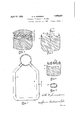
In the drawings Fig. 2 is a sectional view taken on the line 22 of Fig.1;
Fig. 3 is a fragmentary view showing a forming operation;
Fig. 4 is a sectional view taken on the line 44 of Fig. 3; Fig. 5 is a fragmentary view with the formmg dies removed from mandrel showing saw cut through pipe; i
Fig. 6 is a sectional view taken on the line 66' of Fig. 5;
Fig. 7 shows one of the completed loops attached to a header; and v v Fig. 8 is a sectional view taken on the line 88 of Fig. 7.
Referring to the drawings, a length of flat pipe 10 is coiled about a mandrel 11'. The mandrel may be of any suitable shape to conform with the configuration of the, finished product. The top side of the mandrel is provided with a groove 12 which extends the entire length of the mandrel intermediate the edges thereof. The groove 12 is adapted to receive a die or swaging member 18. The die or swaging member is provided, transversely thereof, with spaced, semi-circular... grooves 14, each of which receives a turn of the coiled pipe. The die or swaging member 13 is then elevated above the plane of the mandrel 11, by means of a removable bar or wedge 15, thereby providing a space between the top of the mandrel and the pipe'10. This space is provided in order to permit shaping a portion of each turn of pipe into a cylindrical form without deforming other portions thereof.- In practice, it is preferable first to assem-' 'member'13, is then placed in an inverted po sition upon the turns of the coiled pipe 10, so that the grooves ofeach of the die or swagingmembers are opposite,*with each pair of grooves having a portion of a turn of the coil between them.
By means of a press (not shown), the die or swaging member 16 is forced downwardly into contact with the die or swaging member 13, so that their opposing grooves unite to form a cylindrical recess, thereby forcing that portion of the pipe which is between these members into a cylindrical shape. The
.means, such as a saw 20. The natural spring of the loops thus formed, permits them to be easily removed from the mandrel; and, as they are usually constructed of copper, each loop may be readily bent by hand into the desired shape to fit into the opening in header shown in Fig. 7. It is readily apparent that the process described may be employed in any case where it is desirable to provide end portions of one cross-section on pipe loops of another cross-section by the use of suitable die or swaging members.
Whilethe form of embodiment of the 1nvention as herein disclosed, constitutes a preferred .form, it is to be understood that other forms might be adapted, all coming within the scope of the -claims which follow.
Whatis claimed is as follows:
1. Apparatus for making pipe loops having portions of different cross-sectional contour comprising, a two-part swedging die providing a plurality of die recesses each for receiving a portion of a turn of a pipe coil, a mandrel having provisions for receiving one of the die members so that each turn of the pipe which is wrapped around the mandrel will be received by a die recess in said die member, and means carried by the mandrel for supporting said die member and movable relative to the mandrel to permit retracting said die member from the pipe coil.
'2. Apparatus according to claim 1 in which the mandrel is provided with a longitudinally extendinggroove'for receiving one of the die members, and a removable bar for spacing 7 providing a plurality of die recesses each for receiving a portion of a turn of a pipe coil, a mandrel havlng provisions for receiving one ofthe die members so that each turn of the pipe which is wrapped around the mandrel will be received .by a die recess in said (he member, and means carried by the mandrel for supporting said die member, said means being adapted to permit retracting said die member within the surface of the mandrel.
AL. Apparatus for making pipe loops having portions of different cross-sectional contour comprising a mandrel for coiling pipe, the mandrel including swedging means ada ated to enga e onl a ortion of each tour comprising a mandrel for coiling pipe,
the mandrel including movable swedging means, and means for holding the swedging means in engagement with the coil.
7. Apparatus for making pipe loops having portions oi different cross-sectional contour comprising a mandrel for coiling pipe and means removably positioned within a longitudinal recess of the mandrel for swedging a portion of each convolution of the coil. In testimony whereof I hereto afliX my signature OTTO M. SUMMERS.
Priority Applications (1)
| Application Number | Priority Date | Filing Date | Title |
|---|---|---|---|
| US329368A US1854567A (en) | 1927-01-31 | 1928-12-31 | Apparatus for making pipe loops |
Applications Claiming Priority (2)
| Application Number | Priority Date | Filing Date | Title |
|---|---|---|---|
| US164880A US1732343A (en) | 1927-01-31 | 1927-01-31 | Method of forming pipe loops |
| US329368A US1854567A (en) | 1927-01-31 | 1928-12-31 | Apparatus for making pipe loops |
Publications (1)
| Publication Number | Publication Date |
|---|---|
| US1854567A true US1854567A (en) | 1932-04-19 |
Family
ID=26860944
Family Applications (1)
| Application Number | Title | Priority Date | Filing Date |
|---|---|---|---|
| US329368A Expired - Lifetime US1854567A (en) | 1927-01-31 | 1928-12-31 | Apparatus for making pipe loops |
Country Status (1)
| Country | Link |
|---|---|
| US (1) | US1854567A (en) |
-
1928
- 1928-12-31 US US329368A patent/US1854567A/en not_active Expired - Lifetime
Similar Documents
| Publication | Publication Date | Title |
|---|---|---|
| US2845695A (en) | Method of making refrigerating tubing | |
| US1862281A (en) | Method of manufacturing brake hangers | |
| US1553060A (en) | Process of forming a clevis | |
| US1925721A (en) | Method of making yoke ends | |
| US2166109A (en) | Method of making tubing for refrigerating apparatus | |
| US1854567A (en) | Apparatus for making pipe loops | |
| US2312094A (en) | Method of making hollow propellers | |
| US2182342A (en) | Method and apparatus for making helices without the aid of a core or mandrel | |
| US2691813A (en) | Method of constructing refrigeration evaporators | |
| US2026007A (en) | Coil spring | |
| US2206740A (en) | Nut and method of forming same | |
| US1786571A (en) | Method of making heat-exchanger tubes | |
| US2519820A (en) | Method of making condenser tubes | |
| US3546763A (en) | Heat exchangers and the method of making same | |
| US2995807A (en) | Heat exchangers and methods of making the same | |
| US1732343A (en) | Method of forming pipe loops | |
| US1370328A (en) | Method of making tubes | |
| US1479279A (en) | Method of making return bends | |
| US1319838A (en) | Appabattis fob reducing bods and tubes | |
| US1415620A (en) | Method of making piston rings | |
| US2060858A (en) | Method of making the rods and blank therefor | |
| US1548603A (en) | Method of making claw hammers in one heat | |
| US1906648A (en) | Method of making hinges | |
| US2102941A (en) | Method of forming bolt heads | |
| US2665547A (en) | Method of producing chain-links |