US1854559A - Advertising display wheel - Google Patents
Advertising display wheel Download PDFInfo
- Publication number
- US1854559A US1854559A US547347A US54734731A US1854559A US 1854559 A US1854559 A US 1854559A US 547347 A US547347 A US 547347A US 54734731 A US54734731 A US 54734731A US 1854559 A US1854559 A US 1854559A
- Authority
- US
- United States
- Prior art keywords
- display
- wheel
- display wheel
- advertising
- segments
- Prior art date
- Legal status (The legal status is an assumption and is not a legal conclusion. Google has not performed a legal analysis and makes no representation as to the accuracy of the status listed.)
- Expired - Lifetime
Links
- RYGMFSIKBFXOCR-UHFFFAOYSA-N Copper Chemical compound [Cu] RYGMFSIKBFXOCR-UHFFFAOYSA-N 0.000 description 2
- 229910052802 copper Inorganic materials 0.000 description 2
- 239000010949 copper Substances 0.000 description 2
- 230000005484 gravity Effects 0.000 description 2
- 239000006096 absorbing agent Substances 0.000 description 1
- 239000010432 diamond Substances 0.000 description 1
- 229910003460 diamond Inorganic materials 0.000 description 1
- 239000010437 gem Substances 0.000 description 1
- 229910001751 gemstone Inorganic materials 0.000 description 1
- 230000037431 insertion Effects 0.000 description 1
- 238000003780 insertion Methods 0.000 description 1
- 230000000717 retained effect Effects 0.000 description 1
- 230000035939 shock Effects 0.000 description 1
- 230000003584 silencer Effects 0.000 description 1
- 210000002105 tongue Anatomy 0.000 description 1
Images

Classifications
-
- A—HUMAN NECESSITIES
- A47—FURNITURE; DOMESTIC ARTICLES OR APPLIANCES; COFFEE MILLS; SPICE MILLS; SUCTION CLEANERS IN GENERAL
- A47F—SPECIAL FURNITURE, FITTINGS, OR ACCESSORIES FOR SHOPS, STOREHOUSES, BARS, RESTAURANTS OR THE LIKE; PAYING COUNTERS
- A47F5/00—Show stands, hangers, or shelves characterised by their constructional features
- A47F5/02—Rotary display stands
- A47F5/03—Rotary display stands with horizontal rotation axis
Definitions
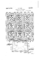
- Theobject of my invention is to provide a novel advertising display wheel, the exposed portion of which is square in shape; to provide means for revolving the wheel to 1 provide novel holders for displaying art cles or jewelry in a continuously upright po-sitlon; and to provid'e novel segmental signs bearing advertising or printed matter which is alternately dis-played and'shifted to a concealed position.
- Fig. '3 is a section on line 3'-3 of F g. 4;
- Fig.4 is a section on line 44 of Fig. 3;
- Fig. 5 is a detail perspectiveview of one of the display segments
- Fig. 6 is a detail perspective view of the means for keepingthe display holders from being rotated while the main display wheel is operated; and- Z5 Fig. 7 is a group of detail views of members 28; 29 '31 and 32, namely a front plan,-a side elevation, and a section-of said members.
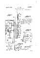
- I provide a suitable base or supporting stand 1' Within which is mounted a suitable electric motor 2 operatively'connecte'd' with suitable encased reduction mechanism 3 from which 33 extends a shaft- 4 driven at greatlyred'uced speed, this shaft4 carrying a beveled gear 5 meshing with a beveled gear 6' on shaft 7 which carries a suitable disc or discs 8 carrying a projection 10 adapted to engage the slotted portions of a Geneva Wheel 9 to produce an'inte'rmi-ttent motion of same.
- a suitable electric motor 2 operatively'connecte'd' with suitable encased reduction mechanism 3 from which 33 extends a shaft- 4 driven at greatlyred'uced speed, this shaft4 carrying a beveled gear 5 meshing with a beveled gear 6' on shaft 7 which carries a suitable disc or discs 8 carrying a projection 10 adapted to engage the slotted portions of a Geneva Wheel 9 to produce an'inte'rmi-ttent motion of same.
- Geneva wheel-'9 is mounted on a shaft 11 which carries. a disc 12'which is attached to the display wheel or device.
- This display wheel consists of a rear wall 13, side walls 14 and front wall 1 5 and preferably is made in the form of a square as shown in Figs. 1 and of-the drawings.
- the front wheel is provided with a series "of suitableopenings 16 through which print- 1931. 9 Serial No. 547,347.
- a display segment 17 is pivotally mounted on a shaft 18 which in turn is mounted in suitable brackets 19 secured to the rear P wall 13, as shown in Fig. 4.
- I also provide a. series of shafts 20 disposed 1n a suitable or symmetrical arrangement in the front wall 15 of the main display wheel and carrying a weight member 21 concealed within the casing.
- a suitable disc 22 On the outer end of each 6! of the shafts 20 is mounted a suitable disc 22 which is provided with a stationary hook 23 and with aplurality of adjustable or movable hooks 25 adapted to releasably engage an ary A ticle, such as a watch 27 and hold it in exposed 65 position on the display disc.
- the hooks 25 are mounted on slidable supports 24 which are slidably mounted in the radial slots 30 in the disc 22. Each of these slid'able supports 24 is attached to a corresponding spring 26 which. in turn is suitably attached to the disc. While four of the hooks 25,.supports 24, springs 2.6 and slots 3O are shown, it'is Withinthe contemplation of my invention to provide any suitable'number of these elements for engaging the particular article, the preferred number and arrangementhowever being as shown in the drawings.
- the shaft 20 is loosely mounted in the front wall 15-.
- I provide a plurality of ring and'jewel supports consisting of a preferably diamond" shaped mounting28 having a ring groove or slit 29;
- mounting 28 is also provided with cut-out rearwardly bent tongues 31 between which extends the slit or groove 29 to permit of the insertion of a ring.
- the operating means for the device is the motor2 which through the reduction'gearin-g mechanism 3 drives the shaft 4 at a comparatively slow speed.
- This shaft in turndriveS the shaft 7 and discs 8 which intermittently operate the Geneva wheel 9,. shaft. 11 :on which it is mounted and disc 12 which is afiixed to the rear wall of the display device, thus revolving the display wheel, I prefer to provide a balance weight 33 0-11 shaft 11.
- the display wheel carries a series of article holding plates having the hooks 23 to which the rings of watches may be secured, the bodies of the watches being engaged by the spring controlled or adjustable hooks 25.
- the article supporting discs are mounted on the shafts 20 and as these shafts are loosely mounted in the front wall 15 and weighted by the weights 21, they are kept from rotating and the watches are continuously held in the same position whether the main display wheel is stationary or revolving.
- segmental sign display devices With each quarter revolution of the main display wheel, a portion of the segmental sign display devices are moved from one of their extreme positions in which one line of advertising which they carry is displayed, to the reverse display position in which the other advertising line which they carry is brought into a displayed position through the opening 16 as will be readily understood by referring to thestructure shown in Figs. 4 and 5 of the drawings.
- the advertising matter or signs placed on the sign display segment 17 are arranged in reverse position so that when the main display wheel is in such a position that the upper line of advertising matter is visible the lower line of advertising matter which is in a reversed or up-side-do-wn position is concealed; and that when the main display wheel has made a one-half revolution the concealed matter will be brought into view by the swinging of the segments to bring the previously concealed advertising matter into a position of visibility through the openings 16.
- the Geneva wheel movement which I prefer to use will turn the main display wheel one-quarter turn at a speed of about one movement every fifteen seconds.
- the front wall 15 of the display wheel preferably consists of a copper plate covered with felt or velvet cut in such shape that lugs 31 can be turned under to hold the ring mountings on the wheel.
- lVhat I claim is 1.
- a display wheel revoluble at a slow rate of speed
- means carried by the display wheel for holding articles of merchandise in a right side up position while the display wheel revolves
- the display wheel having a series of openings
- display segments mounted on and within the display wheel and carrying advertising matter visible through'said openings, said segments being arranged to shift their position as the wheel revolves to change the advertising display with each half revolution of the wheel.
- a display wheel a gravity-weighted article receptacle mounted on said wheel, said receptacle having a plurality of radial slots, spring-controlled hook supports slidably mounted in said slots, and hooks on said supports releasably engaging the article to be displayed.
- an advertising display wheel said wheel having a series of openings in same, a corresponding series of pivotally mounted display segments either half of which may be brought into registration with the aforesaid openings, and adapted to be reversed to display different advertising matter.
- a revoluble display wheel the front wall of said display wheel consisting of a copper plate covered with felt or velvet, the display wheel having slots and turned-in lugs to receive and display rings, article holding devices loosely mounted in the display wheel, weight means connected with same whereby the article holding devices are retained in a position to hold the article continuously upright while the display wheel revolves, and means for rotating the display wheel.
- spring clips mounted on the rear side of the front wall of the display wheel and adapted to releasably engage the rings to hold same.
- a revoluble display wheel comprising front, side and rear walls, the front wall having display openings through same, pivotally mounted display segments carrying advertising matter, one-half of the segments being in view through the openings, and the other half being concealed until the display wheel revolves to a point where the segments will reverse themselves by gravity, and a felt pad mounted on the rear wall of the display wheel to silence the operation of the segments as they reverse themselves when the display Wheel revolves.
- a revoluble display device consisting of a hollow square box-like structure having spaced rear and front walls, article holding devices mounted on the front Wall, shafts on which said article holding devices are afiixed, each of said shafts being loosely supported in the front Wall, weights on said shafts concealed within the display device to retain the article holders in an upright position regardless of the revolving of the display device as a whole, openings in the front wall of the display device for the display of advertising matter, segments pivotally mounted on and within the display wheel and carrying advertising matter, said segments being arranged to reverse their position by gravity as the display device revolves.
- power controlled means for intermittently revolving the display Wheel at a slow speed.
Landscapes
- Displays For Variable Information Using Movable Means (AREA)
Description
H- T. ORR
ADVERTI S ING DI SPLAY WHEEL A ril 19, 1932.
5 Sheets-Sheet 1 Filed June 27, 1931 April 19, 1932. v ORR 1,854,559
' ADVERTISING DISPLAY WHEEL Filed June 27, 1931 3 Sheets-Sheet 2 April 19, 1932. H; T. ORR
ADVERTI S I NG DI S PLAY WHEEL 3 Sheets-Sheet 5 VVOFIJ. Over h Filed June 27, 1951 Time H26 h tarulcnrol' Patented Apr. 19, 1932 HARRY TRACY ORR, OF CHARLOTTE, NORTH CAROLINA ADVERTISING DISPLAY WHEEL Application filed June 27,
Theobject of my invention is to provide a novel advertising display wheel, the exposed portion of which is square in shape; to provide means for revolving the wheel to 1 provide novel holders for displaying art cles or jewelry in a continuously upright po-sitlon; and to provid'e novel segmental signs bearing advertising or printed matter which is alternately dis-played and'shifted to a concealed position. I attain these and other objects of my invention by the apparatus illustrated in theaccompanying drawings, in which- Figure 1 is a front plan view of my 1nvention, the operating mechanism being shown in dotted lines;
2' is a side elevation of the inventlon;
Fig. '3 is a section on line 3'-3 of F g. 4;
Fig.4 is a section on line 44 of Fig. 3;
Fig. 5 is a detail perspectiveview of one of the display segments;
Fig. 6 is a detail perspective view of the means for keepingthe display holders from being rotated while the main display wheel is operated; and- Z5 Fig. 7 is a group of detail views of members 28; 29 '31 and 32, namely a front plan,-a side elevation, and a section-of said members.
Like numerals design-ate like parts in each of-the severalviews.
Referring to the accompanying drawings,
I providea suitable base or supporting stand 1' Within which is mounted a suitable electric motor 2 operatively'connecte'd' with suitable encased reduction mechanism 3 from which 33 extends a shaft- 4 driven at greatlyred'uced speed, this shaft4 carrying a beveled gear 5 meshing with a beveled gear 6' on shaft 7 which carries a suitable disc or discs 8 carrying a projection 10 adapted to engage the slotted portions of a Geneva Wheel 9 to produce an'inte'rmi-ttent motion of same. The
Geneva wheel-'9 is mounted on a shaft 11 which carries. a disc 12'which is attached to the display wheel or device. This display wheel consists of a rear wall 13, side walls 14 and front wall 1 5 and preferably is made in the form of a square as shown in Figs. 1 and of-the drawings.
The front wheel is provided with a series "of suitableopenings 16 through which print- 1931. 9 Serial No. 547,347.
ed matter on a display segment 17 is visible. Each of these display segments 17 is pivotally mounted on a shaft 18 which in turn is mounted in suitable brackets 19 secured to the rear P wall 13, as shown in Fig. 4. I also provide a. series of shafts 20 disposed 1n a suitable or symmetrical arrangement in the front wall 15 of the main display wheel and carrying a weight member 21 concealed within the casing. On the outer end of each 6!) of the shafts 20 is mounted a suitable disc 22 which is provided with a stationary hook 23 and with aplurality of adjustable or movable hooks 25 adapted to releasably engage an ary A ticle, such as a watch 27 and hold it in exposed 65 position on the display disc. The hooks 25 are mounted on slidable supports 24 which are slidably mounted in the radial slots 30 in the disc 22. Each of these slid'able supports 24 is attached to a corresponding spring 26 which. in turn is suitably attached to the disc. While four of the hooks 25,.supports 24, springs 2.6 and slots 3O are shown, it'is Withinthe contemplation of my invention to provide any suitable'number of these elements for engaging the particular article, the preferred number and arrangementhowever being as shown in the drawings. The shaft 20 is loosely mounted in the front wall 15-.
Referring to Figs. 1 and 7, I provide a plurality of ring and'jewel supports consisting of a preferably diamond" shaped mounting28 having a ring groove or slit 29; The
The operating means for the device is the motor2 which through the reduction'gearin-g mechanism 3 drives the shaft 4 at a comparatively slow speed. This shaft in turndriveS the shaft 7 and discs 8 which intermittently operate the Geneva wheel 9,. shaft. 11 :on which it is mounted and disc 12 which is afiixed to the rear wall of the display device, thus revolving the display wheel, I prefer to provide a balance weight 33 0-11 shaft 11.
The display wheel carries a series of article holding plates having the hooks 23 to which the rings of watches may be secured, the bodies of the watches being engaged by the spring controlled or adjustable hooks 25. The article supporting discs are mounted on the shafts 20 and as these shafts are loosely mounted in the front wall 15 and weighted by the weights 21, they are kept from rotating and the watches are continuously held in the same position whether the main display wheel is stationary or revolving.
With each quarter revolution of the main display wheel, a portion of the segmental sign display devices are moved from one of their extreme positions in which one line of advertising which they carry is displayed, to the reverse display position in which the other advertising line which they carry is brought into a displayed position through the opening 16 as will be readily understood by referring to thestructure shown in Figs. 4 and 5 of the drawings. It will be understood that the advertising matter or signs placed on the sign display segment 17 are arranged in reverse position so that when the main display wheel is in such a position that the upper line of advertising matter is visible the lower line of advertising matter which is in a reversed or up-side-do-wn position is concealed; and that when the main display wheel has made a one-half revolution the concealed matter will be brought into view by the swinging of the segments to bring the previously concealed advertising matter into a position of visibility through the openings 16.
The Geneva wheel movement which I prefer to use will turn the main display wheel one-quarter turn at a speed of about one movement every fifteen seconds.
It is within the contemplation of my invention to provide suitable mechanism, in place of the Geneva wheel, for producing a continuous rotation of the main display wheel, such as a series of conventional meshing pinions and gears in place of the disc 8 and Geneva wheel 9 on shafts 7 and 11 respectively.
The front wall 15 of the display wheel preferably consists of a copper plate covered with felt or velvet cut in such shape that lugs 31 can be turned under to hold the ring mountings on the wheel.
I prefer to provide a felt pad on the inside of the rear wall 13 of the display wheel to act as a shock absorber or silencer of the ad vertising display segments when they reverse themselves as the display wheel rotates.
lVhat I claim is 1. In an advertising device of the character described, the combination of a display wheel revoluble at a slow rate of speed, means carried by the display wheel for holding articles of merchandise in a right side up position while the display wheel revolves, the display wheel having a series of openings, and display segments mounted on and within the display wheel and carrying advertising matter visible through'said openings, said segments being arranged to shift their position as the wheel revolves to change the advertising display with each half revolution of the wheel.
2. In an advertising device of the character described, the combination of a display wheel, a gravity-weighted article receptacle mounted on said wheel, said receptacle having a plurality of radial slots, spring-controlled hook supports slidably mounted in said slots, and hooks on said supports releasably engaging the article to be displayed.
3. In an advertising display wheel of the type described, the combination of a revoluble display wheel, a series of weighted shafts loosely mounted in the wheel, articleholding receptacles on said shafts, and a hook on the upper portion of each of said receptacles to hold an article to be displayed.
1. In an advertising device of the character described, the combination of an advertising display wheel, said wheel having a series of openings in same, a corresponding series of pivotally mounted display segments either half of which may be brought into registration with the aforesaid openings, and adapted to be reversed to display different advertising matter.
5. In an advertising device of the character described, the combination of a revoluble display wheel, the front wall of said display wheel consisting of a copper plate covered with felt or velvet, the display wheel having slots and turned-in lugs to receive and display rings, article holding devices loosely mounted in the display wheel, weight means connected with same whereby the article holding devices are retained in a position to hold the article continuously upright while the display wheel revolves, and means for rotating the display wheel.
6. In combination with the device defined in claim 5, spring clips mounted on the rear side of the front wall of the display wheel and adapted to releasably engage the rings to hold same.
7 In a display wheel of the type described, the combination of a revoluble display wheel comprising front, side and rear walls, the front wall having display openings through same, pivotally mounted display segments carrying advertising matter, one-half of the segments being in view through the openings, and the other half being concealed until the display wheel revolves to a point where the segments will reverse themselves by gravity, and a felt pad mounted on the rear wall of the display wheel to silence the operation of the segments as they reverse themselves when the display Wheel revolves.
8. In an advertising device of the character described, the combination of a revoluble display device consisting of a hollow square box-like structure having spaced rear and front walls, article holding devices mounted on the front Wall, shafts on which said article holding devices are afiixed, each of said shafts being loosely supported in the front Wall, weights on said shafts concealed within the display device to retain the article holders in an upright position regardless of the revolving of the display device as a whole, openings in the front wall of the display device for the display of advertising matter, segments pivotally mounted on and within the display wheel and carrying advertising matter, said segments being arranged to reverse their position by gravity as the display device revolves.
9. In combination with the apparatus defined in claim 8, power controlled means for intermittently revolving the display Wheel at a slow speed.
HARRY TRACY ORR.
Priority Applications (1)
| Application Number | Priority Date | Filing Date | Title |
|---|---|---|---|
| US547347A US1854559A (en) | 1931-06-27 | 1931-06-27 | Advertising display wheel |
Applications Claiming Priority (1)
| Application Number | Priority Date | Filing Date | Title |
|---|---|---|---|
| US547347A US1854559A (en) | 1931-06-27 | 1931-06-27 | Advertising display wheel |
Publications (1)
| Publication Number | Publication Date |
|---|---|
| US1854559A true US1854559A (en) | 1932-04-19 |
Family
ID=24184296
Family Applications (1)
| Application Number | Title | Priority Date | Filing Date |
|---|---|---|---|
| US547347A Expired - Lifetime US1854559A (en) | 1931-06-27 | 1931-06-27 | Advertising display wheel |
Country Status (1)
| Country | Link |
|---|---|
| US (1) | US1854559A (en) |
Cited By (1)
| Publication number | Priority date | Publication date | Assignee | Title |
|---|---|---|---|---|
| US11944193B1 (en) * | 2022-11-15 | 2024-04-02 | Eran Swears | Multi-wheel rotational shelving assembly |
-
1931
- 1931-06-27 US US547347A patent/US1854559A/en not_active Expired - Lifetime
Cited By (1)
| Publication number | Priority date | Publication date | Assignee | Title |
|---|---|---|---|---|
| US11944193B1 (en) * | 2022-11-15 | 2024-04-02 | Eran Swears | Multi-wheel rotational shelving assembly |
Similar Documents
| Publication | Publication Date | Title |
|---|---|---|
| US2194238A (en) | Display device | |
| JPH08504956A (en) | Transparent analog clock | |
| US2709004A (en) | Display stand | |
| US1875563A (en) | Display stand | |
| US4490932A (en) | Advertising sign support | |
| US2152424A (en) | Designoscope | |
| US1854559A (en) | Advertising display wheel | |
| MXPA04007893A (en) | Rotary display apparatus for displaying periodicals in a circular array. | |
| US2258351A (en) | Advertising horoscope machine | |
| US2586641A (en) | Advertising display clock | |
| US2273604A (en) | Display apparatus | |
| US2839855A (en) | Displays | |
| US2332845A (en) | Movable display device | |
| US1968759A (en) | Display device | |
| US1009839A (en) | Display apparatus. | |
| JP2004212266A (en) | Exhibiting device | |
| US1612362A (en) | Display device | |
| US1598277A (en) | Display device | |
| US2123285A (en) | Spinning wheel | |
| CN114343378B (en) | Tourist souvenir display cabinet | |
| US2204952A (en) | Astronomical toy | |
| US937366A (en) | Display-stand. | |
| US1746581A (en) | Multiple revolving sign | |
| US2087187A (en) | Moving stand for the display of goods, signs, and the like | |
| EP1045299B1 (en) | Timepiece |