US1854556A - Inner tube tester - Google Patents
Inner tube tester Download PDFInfo
- Publication number
- US1854556A US1854556A US225327A US22532727A US1854556A US 1854556 A US1854556 A US 1854556A US 225327 A US225327 A US 225327A US 22532727 A US22532727 A US 22532727A US 1854556 A US1854556 A US 1854556A
- Authority
- US
- United States
- Prior art keywords
- inner tube
- tube
- tank
- spider
- superstructure
- Prior art date
- Legal status (The legal status is an assumption and is not a legal conclusion. Google has not performed a legal analysis and makes no representation as to the accuracy of the status listed.)
- Expired - Lifetime
Links
- 241000239290 Araneae Species 0.000 description 10
- XLYOFNOQVPJJNP-UHFFFAOYSA-N water Substances O XLYOFNOQVPJJNP-UHFFFAOYSA-N 0.000 description 9
- 210000005069 ears Anatomy 0.000 description 2
- 239000012530 fluid Substances 0.000 description 2
- 238000000034 method Methods 0.000 description 2
- 241001517310 Eria Species 0.000 description 1
- 238000010276 construction Methods 0.000 description 1
- 239000002184 metal Substances 0.000 description 1
- 239000007787 solid Substances 0.000 description 1
Images
Classifications
-
- G—PHYSICS
- G01—MEASURING; TESTING
- G01M—TESTING STATIC OR DYNAMIC BALANCE OF MACHINES OR STRUCTURES; TESTING OF STRUCTURES OR APPARATUS, NOT OTHERWISE PROVIDED FOR
- G01M3/00—Investigating fluid-tightness of structures
- G01M3/02—Investigating fluid-tightness of structures by using fluid or vacuum
- G01M3/26—Investigating fluid-tightness of structures by using fluid or vacuum by measuring rate of loss or gain of fluid, e.g. by pressure-responsive devices, by flow detectors
- G01M3/32—Investigating fluid-tightness of structures by using fluid or vacuum by measuring rate of loss or gain of fluid, e.g. by pressure-responsive devices, by flow detectors for containers, e.g. radiators
- G01M3/3218—Investigating fluid-tightness of structures by using fluid or vacuum by measuring rate of loss or gain of fluid, e.g. by pressure-responsive devices, by flow detectors for containers, e.g. radiators for flexible or elastic containers
Definitions
- Our invention relates to improvements in inner tube testers, and it consists in the com- Y spectto the tank 1, a piston; disislidably/disbinat-ions, constructions, and arrangements hereinafter described and claimed.
- An object of our invention is to provide an inner tube tester which is pneumatically controlled, and which makes use of means for moving the inner tube into a body of water,
- a further object of our invention is to provide a device of the type described which is .these ears being provided "With: openings forextremely simple in constructionand which is durable and efiicient for the purpose intended.
- Figure 2 is a section along the line 2-2 of Figure 1;
- Figure 3 is a section along the line 33 of Figure 1.
- a tank 1 having a tube submerging superstructure supported by a frame work 2, the latter being secured to the tankby bolts 3, or other suitable fastening means.
- the tank is large enough to hold an inflated tube and a sufiicient quantity of water 4 is kept in the tank for entirely covering the tube when the latter is moved down into the body of water.
- the superstructure comprises three uprights which are spaced apart from each other, so that one-half of the area of the tank is clear and will receive an inflated tube with- P out the necessity of having to bend a tube out of shape, or of moving any of the tube submerging apparatus. It is obvious that any number of uprights 2 may be provided. or that a solid piece of metal may be substituted for the uprights without departing 5 from the spirit and scope of our invention.
- the superstructure Z carries a cylinderfi that is preferably centrally disposedtwithreposed in the cylinder andis-connectedtoa spider 7 by means of a piston rodi'8., Air,-'
- the spider as comprising arms which ,eXtend radially from a disc 9.
- the 7 disc .9 there is mounted a second disc-.10
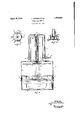
- VThejpipe 25 Figure 1 is a side elevation of the device, 2' m y V- IIBC l ia-sour v f mo rious parts of, the .device, the operatiomthereof may be readily understood. y
- the spider 7 is normally held in the full line position shown in Figure 1 by the springs 12.
- the inner tube to be tested is moved into the space made by the uprights of the superstructure and is placed upon the body of the water 4.
- the valve 15 is now opened and will quickly force*'* the spider 7 downwardly, the spider carrying with it the inner tube.
- the valve may be closed when the tube is entirely submerged and then the operator can detect the various places where leaks are occurring in the tube.
- valve 16 is opened and valve 15 is closed if this has not been done before and the springs, together with the force exerted by the buoy- 5 ancy of the inner tube, will move the spider 7 upwardly, leaving a free space through which the tube can be removed from the de vice.
- This operation consumes very little time and is practically the only method of 10 entirely submerging an innertube.
- the old method of submerging the tube by hand takes about nine operations. This device does it in one operation.
- An inner tube tester comprising a tank for holding water, a cylinder disposed above said tank, a superstructure for supporting said cylinder and having a space large enough to permit an inner tube to be placed upon a body of water without moving any of the operating parts of the tester, a piston mounted in said cylinder, a spider operatively connected to said piston, and means for controlling the flow of fluid into and out of said cylinder.
- An inner tube tester comprising a tank for holding water, a superstructure carried by said tank, and providing an opening extending at least 180 degrees around the top of the tank, a cylinder carried by said superstructure, a piston mounted in said cylinder, a spider operatively connected to said piston, means for lifting said spider clear of the tank for permitting an inner tube to be moved beneath the spider and through the opening afforded by the superstructure, and manually controlled pneumatic means for admitting fluid to and from the cylinder.
Landscapes
- Physics & Mathematics (AREA)
- General Physics & Mathematics (AREA)
- Testing Of Devices, Machine Parts, Or Other Structures Thereof (AREA)
Description
April 19, 1932.
A. MOEBES ET AL INNER TUBE TESTER Filed Oct. 10, 1927 JOSEPH J4 M58 HOP/MA N ATTORNEYS Patented Apr. 19, 1932 AUGUST MOEIBES AND JOSEPH JAMESIHOFEMAN, F .ViIISALIA,; CALIFQRNIA INNER TUBE TESTER.
Application filed October 10,1927. ..s'eria.1:noizzasev.
Our invention relates to improvements in inner tube testers, and it consists in the com- Y spectto the tank 1, a piston; disislidably/disbinat-ions, constructions, and arrangements hereinafter described and claimed.
An object of our invention is to provide an inner tube tester which is pneumatically controlled, and which makes use of means for moving the inner tube into a body of water,
this means extending clear of the tank when tube to be quickly disposed beneath the means in preparation for testing the tube A further object of our invention is to provide a device of the type described which is .these ears being provided "With: openings forextremely simple in constructionand which is durable and efiicient for the purpose intended.
Other objects and advantages will appear in the following specification, and the novel features of our invention will be particularly pointed out in the appended claims.
Our invention is illustrated in the accompanying drawings forming a part of this application, in which:
a portion of the tank being broken away;
Figure 2 is a section along the line 2-2 of Figure 1; and
Figure 3 is a section along the line 33 of Figure 1.
In carrying out our invention we provide a tank 1 having a tube submerging superstructure supported by a frame work 2, the latter being secured to the tankby bolts 3, or other suitable fastening means. The tank is large enough to hold an inflated tube and a sufiicient quantity of water 4 is kept in the tank for entirely covering the tube when the latter is moved down into the body of water.
The superstructure comprises three uprights which are spaced apart from each other, so that one-half of the area of the tank is clear and will receive an inflated tube with- P out the necessity of having to bend a tube out of shape, or of moving any of the tube submerging apparatus. It is obvious that any number of uprights 2 may be provided. or that a solid piece of metal may be substituted for the uprights without departing 5 from the spirit and scope of our invention.
in operativeposition, for permitting an inner The superstructure Zcarries a cylinderfi that is preferably centrally disposedtwithreposed in the cylinder andis-connectedtoa spider 7 by means of a piston rodi'8., Air,-'
when -admittedinto the cyli11cler,-will force the piston rod ,8. andspider 7 downwardly \lIItO. the dotted line position; shown in Figurel.
In the presentform of thedevice wehave shown the spider as comprising arms which ,eXtend radially from a disc 9. Directly above. 7 the 7 disc .9 there is mounteda second disc-.10
that has ears 11 struck upwardly therefrom,
receiving the ends of the coiled springs; 12.
f The upper' ends of thespringsare connected to the top of, the superstructure 2. -I*"ig ures: 2
amides-clearly showvhow the spideriscon- .inected tothe pistonrrod and how the; arms of -.thespider progectradially' from the disc 9.
.zAn air pipe13 communicates withthe cylinder 5 at l l and, is provided withaan[inlet valve 15, and anexhaust valve 16. VThejpipe 25 Figure 1 is a side elevation of the device, 2' m y V- IIBC l ia-sour v f mo rious parts of, the .device, the operatiomthereof may be readily understood. y
It is essential in' ntestingvthe inner tubes that the entire tube beisubmerged at the same time, in order that all leaks may be noticed. Since the advent of the balloon tire it takes considerable force to submerge an inflated balloon tube in a body of water.
It is for this reason that air was resorted to so that suflicient power could be applied to the inner tube in order to force it beneath the surface of the water. The spider 7 is normally held in the full line position shown in Figure 1 by the springs 12. The inner tube to be tested is moved into the space made by the uprights of the superstructure and is placed upon the body of the water 4. The valve 15 is now opened and will quickly force*'* the spider 7 downwardly, the spider carrying with it the inner tube. The valve may be closed when the tube is entirely submerged and then the operator can detect the various places where leaks are occurring in the tube.
After these places have been marked the valve 16 is opened and valve 15 is closed if this has not been done before and the springs, together with the force exerted by the buoy- 5 ancy of the inner tube, will move the spider 7 upwardly, leaving a free space through which the tube can be removed from the de vice. This operation consumes very little time and is practically the only method of 10 entirely submerging an innertube. The old method of submerging the tube by hand takes about nine operations. This device does it in one operation.
Although we have shown and described one embodiment of our invention, it is to be understood that the same is susceptible of various changes and we reserve the right to employ such changes as may come within the scone of the appended claims.
We claim:
1. An inner tube tester comprising a tank for holding water, a cylinder disposed above said tank, a superstructure for supporting said cylinder and having a space large enough to permit an inner tube to be placed upon a body of water without moving any of the operating parts of the tester, a piston mounted in said cylinder, a spider operatively connected to said piston, and means for controlling the flow of fluid into and out of said cylinder.
2. An inner tube tester comprising a tank for holding water, a superstructure carried by said tank, and providing an opening extending at least 180 degrees around the top of the tank, a cylinder carried by said superstructure, a piston mounted in said cylinder, a spider operatively connected to said piston, means for lifting said spider clear of the tank for permitting an inner tube to be moved beneath the spider and through the opening afforded by the superstructure, and manually controlled pneumatic means for admitting fluid to and from the cylinder.
AUGUST MOEBES.
JOSEPH JAMES HOFFMAN.
Priority Applications (1)
| Application Number | Priority Date | Filing Date | Title |
|---|---|---|---|
| US225327A US1854556A (en) | 1927-10-10 | 1927-10-10 | Inner tube tester |
Applications Claiming Priority (1)
| Application Number | Priority Date | Filing Date | Title |
|---|---|---|---|
| US225327A US1854556A (en) | 1927-10-10 | 1927-10-10 | Inner tube tester |
Publications (1)
| Publication Number | Publication Date |
|---|---|
| US1854556A true US1854556A (en) | 1932-04-19 |
Family
ID=22844444
Family Applications (1)
| Application Number | Title | Priority Date | Filing Date |
|---|---|---|---|
| US225327A Expired - Lifetime US1854556A (en) | 1927-10-10 | 1927-10-10 | Inner tube tester |
Country Status (1)
| Country | Link |
|---|---|
| US (1) | US1854556A (en) |
Cited By (3)
| Publication number | Priority date | Publication date | Assignee | Title |
|---|---|---|---|---|
| US2508246A (en) * | 1947-09-25 | 1950-05-16 | Wingfoot Corp | Tube-testing apparatus |
| US2902856A (en) * | 1956-04-23 | 1959-09-08 | Consumers Tire & Supply Co Inc | Means for locating punctures in tubeless tires |
| US4041772A (en) * | 1976-08-27 | 1977-08-16 | Consumer Tire & Supply Co., Inc. | Apparatus for locating punctures in tires |
-
1927
- 1927-10-10 US US225327A patent/US1854556A/en not_active Expired - Lifetime
Cited By (3)
| Publication number | Priority date | Publication date | Assignee | Title |
|---|---|---|---|---|
| US2508246A (en) * | 1947-09-25 | 1950-05-16 | Wingfoot Corp | Tube-testing apparatus |
| US2902856A (en) * | 1956-04-23 | 1959-09-08 | Consumers Tire & Supply Co Inc | Means for locating punctures in tubeless tires |
| US4041772A (en) * | 1976-08-27 | 1977-08-16 | Consumer Tire & Supply Co., Inc. | Apparatus for locating punctures in tires |
Similar Documents
| Publication | Publication Date | Title |
|---|---|---|
| US3762213A (en) | Leak detector | |
| CN204135623U (en) | A kind of elbow pipe welding fixture of rotatable location | |
| US1854556A (en) | Inner tube tester | |
| CN113791081A (en) | A non-destructive testing device for pressure vessel welds | |
| US1973674A (en) | Pipe testing machine | |
| CN108398297B (en) | Rotation type collection equipment for empty gas detection surveys | |
| CN104908536B (en) | A kind of tyre crane cart walking mechanism tire assembling method | |
| FR1223220A (en) | Method, repair accessory and device for repairing tubeless tires on the rim | |
| CN110763710A (en) | A kind of X-ray flaw detection equipment inside the pipeline | |
| US2679092A (en) | Apparatus for repairing and testing radiators | |
| GB401621A (en) | Improvements in tube testing machines | |
| US1972630A (en) | Pipe testing apparatus | |
| CN117347080B (en) | Hub detection device | |
| US2250740A (en) | Tire casing spreader | |
| GB651850A (en) | A new or improved apparatus for pressure testing valves or cocks for controlling the flow of fluids | |
| CN108226209A (en) | Cool-hot fatigue test device and method | |
| CN208366802U (en) | A kind of seepage of water analyzer of efficient detection | |
| US2508246A (en) | Tube-testing apparatus | |
| US1762164A (en) | Testing machine | |
| US1878515A (en) | Tire spreader | |
| US2470204A (en) | Radiator testing device | |
| GB191112049A (en) | Improvements in Apparatus for Testing Barrels for Leakage. | |
| USRE17697E (en) | Hethod of and apparatus for testing cans | |
| CN209148215U (en) | A kind of diesel engine cylinder head waterway seal detection device | |
| JPH0213253B2 (en) |