US1854518A - Cement barrel - Google Patents
Cement barrel Download PDFInfo
- Publication number
- US1854518A US1854518A US456547A US45654730A US1854518A US 1854518 A US1854518 A US 1854518A US 456547 A US456547 A US 456547A US 45654730 A US45654730 A US 45654730A US 1854518 A US1854518 A US 1854518A
- Authority
- US
- United States
- Prior art keywords
- cement
- casing
- barrel
- recess
- discharge
- Prior art date
- Legal status (The legal status is an assumption and is not a legal conclusion. Google has not performed a legal analysis and makes no representation as to the accuracy of the status listed.)
- Expired - Lifetime
Links
Images
Classifications
-
- E—FIXED CONSTRUCTIONS
- E21—EARTH OR ROCK DRILLING; MINING
- E21B—EARTH OR ROCK DRILLING; OBTAINING OIL, GAS, WATER, SOLUBLE OR MELTABLE MATERIALS OR A SLURRY OF MINERALS FROM WELLS
- E21B34/00—Valve arrangements for boreholes or wells
- E21B34/06—Valve arrangements for boreholes or wells in wells
-
- E—FIXED CONSTRUCTIONS
- E21—EARTH OR ROCK DRILLING; MINING
- E21B—EARTH OR ROCK DRILLING; OBTAINING OIL, GAS, WATER, SOLUBLE OR MELTABLE MATERIALS OR A SLURRY OF MINERALS FROM WELLS
- E21B33/00—Sealing or packing boreholes or wells
- E21B33/10—Sealing or packing boreholes or wells in the borehole
- E21B33/13—Methods or devices for cementing, for plugging holes, crevices or the like
- E21B33/14—Methods or devices for cementing, for plugging holes, crevices or the like for cementing casings into boreholes
-
- F—MECHANICAL ENGINEERING; LIGHTING; HEATING; WEAPONS; BLASTING
- F16—ENGINEERING ELEMENTS AND UNITS; GENERAL MEASURES FOR PRODUCING AND MAINTAINING EFFECTIVE FUNCTIONING OF MACHINES OR INSTALLATIONS; THERMAL INSULATION IN GENERAL
- F16K—VALVES; TAPS; COCKS; ACTUATING-FLOATS; DEVICES FOR VENTING OR AERATING
- F16K15/00—Check valves
- F16K15/14—Check valves with flexible valve members
- F16K15/144—Check valves with flexible valve members the closure elements being fixed along all or a part of their periphery
- F16K15/145—Check valves with flexible valve members the closure elements being fixed along all or a part of their periphery the closure elements being shaped as a solids of revolution, e.g. cylindrical or conical
-
- Y—GENERAL TAGGING OF NEW TECHNOLOGICAL DEVELOPMENTS; GENERAL TAGGING OF CROSS-SECTIONAL TECHNOLOGIES SPANNING OVER SEVERAL SECTIONS OF THE IPC; TECHNICAL SUBJECTS COVERED BY FORMER USPC CROSS-REFERENCE ART COLLECTIONS [XRACs] AND DIGESTS
- Y10—TECHNICAL SUBJECTS COVERED BY FORMER USPC
- Y10T—TECHNICAL SUBJECTS COVERED BY FORMER US CLASSIFICATION
- Y10T137/00—Fluid handling
- Y10T137/7722—Line condition change responsive valves
- Y10T137/7837—Direct response valves [i.e., check valve type]
- Y10T137/7859—Single head, plural ports in parallel
- Y10T137/7861—Annular head
-
- Y—GENERAL TAGGING OF NEW TECHNOLOGICAL DEVELOPMENTS; GENERAL TAGGING OF CROSS-SECTIONAL TECHNOLOGIES SPANNING OVER SEVERAL SECTIONS OF THE IPC; TECHNICAL SUBJECTS COVERED BY FORMER USPC CROSS-REFERENCE ART COLLECTIONS [XRACs] AND DIGESTS
- Y10—TECHNICAL SUBJECTS COVERED BY FORMER USPC
- Y10T—TECHNICAL SUBJECTS COVERED BY FORMER US CLASSIFICATION
- Y10T137/00—Fluid handling
- Y10T137/7722—Line condition change responsive valves
- Y10T137/7837—Direct response valves [i.e., check valve type]
- Y10T137/7879—Resilient material valve
- Y10T137/7888—With valve member flexing about securement
- Y10T137/7889—Sleeve
Definitions
- This invention has reference to the art of cementing casing in deep well drilling, and relates particularly to improvements in devices for discharging cement laterally through the walls of the casing or supply tubing.
- a cement barrel or in other words a section of tubing having lateral cement discharge passages, which are preferably provided with outwardly opening check valves so that the discharge cement cannot back up into the casing.
- the cement barrel may be made up in a string of tubing lowered within the casing, the cement barrel being lowered to discharge below the lower end of the casing.
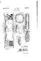
- Fig. 1 is a view showing my cement barrel made up in a string of casing lowered within a well bore;
- Fig. 2 is a longitudinal section through the cement barrel
- Fig. 3 is a transverse section taken on line 33 of Fig. 2;
- Fig. 4 is a fragmentary view taken from Fig. 2 but showing the valve in open position
- Fig. 5 is a section taken on line 5-5 of Fig.
- Fig. 6 shows the cement barrel made up in a string of tubing lowered within a casing in a well bore.
- the numeral 10 designates generally a well bore, and the numeral 11 a. casing lowered therein, and made up in casing 11 at a point at which it is desired to cement the casing in a cement barrel 13.v
- the lower end of casing 11 is here shown carrying a shoe 14 resting onthe bottom of the well hole.
- Valved discharge passages in the side walls of the barrel 13 are designated at 16 in Fig. 1.
- valved passages are shown more particularly in Figs. 2, 3, 4 and 5.
- the body 20 of the barrel is cut with an annular groove or recess 21 providing opposed upper and lower annular shoulders 22 and 23, respectively, the cutpreferably being made deepest at the lower end of the recess so that the lower shoulder 23 is wider than the upper shoulder 22, and with the wall surface 24 that defines the recess between shoulders 22 and 23 extending vertically for a short distance from shoulder 23 and then inclining outwardly to meet the upper shoulder 22, the recess thus formed providing a seat for a valve member presently to be described.
- the wall of the barrel is then drilled approximately in the middle of wall surface 24 with radial, cement-discharge passages 31.
- a resilient ring 32 of rubber or the like Fitted in recess 21 against the inclined seat- 'thereb ing surface 24 of the body is a resilient ring 32 of rubber or the like, t at tapers upwardly in opposition to the taper of the seating surface 24, and the outer surface of which is normally flush with the outer surface of the barrel.
- Straps 33 spaced lietween passages 31 are welded top and bottom to the barrel atthe edges of the roove 21 for the purpose of normally con ning the rubber ring fully seated within its groove.
- liquid cement under pressure is forced down casing 11 and from within body 20 out through the passages 31 and against the inner surface of the resilient ring 32.
- the upper portion of the ring being thinner than the lower portion thereof, flexes outwardly between straps 33 due to the pressure of the cement and allows the cement to escape through the openings thus provided, while the lower, thicker portion of the ring, being less flexible, keeps its seat within the groove 21, as indicated in Fig. 4.
- the resilient ring springs back into its fully seated or closed position, squeezing the cement out of its seat as it does so, and
- Fig. 1 is shown a typical use of the cement barrel, the lower end of the barrel being shown carrying a'shoe through the lower end of which cement may in some cases be discharged, but the shoe being shown resting on the bottom of the hole and the lower discharge passage therefore being shut 011'. With the lower passage shut off, however, suflicient pressure may be put on the cement to force it out through the resilient valve of barrel 13, from which it then flows to fill in as indicated at 34.
- cement barrel need not necessarily be at the lower end of the casing, but may be made up at any point therein required, and further that a number of cement barrels may be made up in the casing to cement in at as many points as may be desirable.
- Fig. 6 shows a cement barrel 13a made up in a string of tubing 40 lowered within a casing 4-1.
- the lower end of the barrel 13a is here shown closed as by means of a bull nose plug 43.
- the cement is in this case forced out of the resilient valve 16 and fills in around the lower end of the casing-as indicated at 44.
- a device of the'character described embodying a tubular body adapted for being made up in a pipe string, said body havin in its outer surface an annular recess, an having a dischargepassage leading from its inside bore through the side wall defining said recess, and a vertically tapering resilient ring seated in said recess.
- a device of the character described embodying a tubular body adapted for being made up in a pipe string, said body having in its outer surface an annular recess, the side wall defining said recess being inclined, and having a discharge passage leading from the inside bore of the body through said side wall to said recess, and a resilient ring tapering oppositely to the incline of the recess side wall seated in said recess.
- a device of the. character described embodying a tubular body adapted for being made up in a pipe string, said body having in its outer surface an annular recess, and having a discharge passage leading from its inside bore through the side wall defining said recess, and a resilient ring seated in said recess and adapted to be flexed radially outwardly under pressure exerted through said discharge passage from inside the tubular body.
- a device of the character described embodying a tubular body adapted to being made up in a pipe string, said body having in its outer surface an annular recess, and having a discharge passage leading from its inside bore through the side wall defining said recess, and a resilient ring seated in said recess, there being a difference in flexibility between the upper and lower portions of said ring such that the more flexible portion of the ring is adapted to be flexed radially outwardly under pressure exerted through said discharge passage from inside the tubular body whereby said discharge passages are uncovered, while the less flexible portion of the ring retains its seat in said recess.
Landscapes
- Engineering & Computer Science (AREA)
- Life Sciences & Earth Sciences (AREA)
- Geology (AREA)
- Mining & Mineral Resources (AREA)
- Physics & Mathematics (AREA)
- Environmental & Geological Engineering (AREA)
- Fluid Mechanics (AREA)
- General Life Sciences & Earth Sciences (AREA)
- Geochemistry & Mineralogy (AREA)
- General Engineering & Computer Science (AREA)
- Mechanical Engineering (AREA)
- Containers And Packaging Bodies Having A Special Means To Remove Contents (AREA)
Description
,J. Q. Ll TTLE CEMENT BARREL April 19, 1932.
Filed May 28, 1950 Inventor. John. 624 LIZ/(e 91% may.
Patented Apr. 19, 1932 rasaaa JOHN G. LITTLE, OF WHITTIER, CALIFORNIA.
CEMENT BARREL Application filed May 28,
This invention has reference to the art of cementing casing in deep well drilling, and relates particularly to improvements in devices for discharging cement laterally through the walls of the casing or supply tubing.
There are many situations in which it is desirable to discharge cement through passages in the side walls of a supply tube or in the casing itself rather than out of the bottom end thereof. One of these is the case in which the cement may initially be discharged from the lower open end of the tubing or casing, but in which discharge from the lower end may, during. the course of the operation, become obstructed due to any one of various causes, or it may be that it is desired to rest the tubing or casing on the bottom of the hole and discharge the cement at a point higher up.
In such situations it is now practice to include in the casing at the point at which the casing is to be cemented .a cement barrel, or in other words a section of tubing having lateral cement discharge passages, which are preferably provided with outwardly opening check valves so that the discharge cement cannot back up into the casing.
In other situations, the cement barrel may be made up in a string of tubing lowered within the casing, the cement barrel being lowered to discharge below the lower end of the casing.
Certain devices of this general type involving mechanical valving arrangements have appeared in the art, but'have involved serious short-comings because of lacking the mechanical simplicity which is necessarily required of such devices.
It is therefore the primary object of the present invention to provide a cement barrel having check valves of the greatest simplicity, to the ends of reducing mechanical complications and disorders in use, as well as cost of manufacture.
It is a further object of the invention to provide a check valve in the barrel which when in normal closed posi ion will be flush or in smooth alignment with the exterior surface of the casing.
1930. Serial No. 456,547.
. How these objects are accomplished, as well as other objects and features of the invention, will be fully understood from the following detailed description of a present preferred embodiment of the invention, reference for this purpose being had to the accompanying drawings, in which:
Fig. 1 is a view showing my cement barrel made up in a string of casing lowered within a well bore;
. Fig. 2 is a longitudinal section through the cement barrel;
Fig. 3 is a transverse section taken on line 33 of Fig. 2;
Fig. 4 is a fragmentary view taken from Fig. 2 but showing the valve in open position;
Fig. 5 is a section taken on line 5-5 of Fig.
3; and
Fig. 6 shows the cement barrel made up in a string of tubing lowered within a casing in a well bore.
The numeral 10 designates generally a well bore, and the numeral 11 a. casing lowered therein, and made up in casing 11 at a point at which it is desired to cement the casing in a cement barrel 13.v The lower end of casing 11 is here shown carrying a shoe 14 resting onthe bottom of the well hole. Valved discharge passages in the side walls of the barrel 13 are designated at 16 in Fig. 1.
These valved passages are shown more particularly in Figs. 2, 3, 4 and 5. As there shown, the body 20 of the barrel is cut with an annular groove or recess 21 providing opposed upper and lower annular shoulders 22 and 23, respectively, the cutpreferably being made deepest at the lower end of the recess so that the lower shoulder 23 is wider than the upper shoulder 22, and with the wall surface 24 that defines the recess between shoulders 22 and 23 extending vertically for a short distance from shoulder 23 and then inclining outwardly to meet the upper shoulder 22, the recess thus formed providing a seat for a valve member presently to be described. The wall of the barrel is then drilled approximately in the middle of wall surface 24 with radial, cement-discharge passages 31.
Fitted in recess 21 against the inclined seat- 'thereb ing surface 24 of the body is a resilient ring 32 of rubber or the like, t at tapers upwardly in opposition to the taper of the seating surface 24, and the outer surface of which is normally flush with the outer surface of the barrel. Straps 33 (see Fig. 5) spaced lietween passages 31 are welded top and bottom to the barrel atthe edges of the roove 21 for the purpose of normally con ning the rubber ring fully seated within its groove.
In operation, liquid cement under pressure is forced down casing 11 and from within body 20 out through the passages 31 and against the inner surface of the resilient ring 32. The upper portion of the ring, being thinner than the lower portion thereof, flexes outwardly between straps 33 due to the pressure of the cement and allows the cement to escape through the openings thus provided, while the lower, thicker portion of the ring, being less flexible, keeps its seat within the groove 21, as indicated in Fig. 4. When the pressure is taken off of the cement within the casing, the resilient ring springs back into its fully seated or closed position, squeezing the cement out of its seat as it does so, and
shuts off the discharged cement outside 0 the casing from backing up through the discharge passages due to the external pressure. The device is here shown with the thin edge of the resilient ring up, which arrangement results in directing the discharged cement in an upward direction, although it will be obvious that these relations may be reversed. In Fig. 1 is shown a typical use of the cement barrel, the lower end of the barrel being shown carrying a'shoe through the lower end of which cement may in some cases be discharged, but the shoe being shown resting on the bottom of the hole and the lower discharge passage therefore being shut 011'. With the lower passage shut off, however, suflicient pressure may be put on the cement to force it out through the resilient valve of barrel 13, from which it then flows to fill in as indicated at 34. It is to be understood, however, that the cement barrel need not necessarily be at the lower end of the casing, but may be made up at any point therein required, and further that a number of cement barrels may be made up in the casing to cement in at as many points as may be desirable.
Fig. 6 shows a cement barrel 13a made up in a string of tubing 40 lowered within a casing 4-1. The lower end of the barrel 13a is here shown closed as by means of a bull nose plug 43. The cement is in this case forced out of the resilient valve 16 and fills in around the lower end of the casing-as indicated at 44.
It will now be recognized that I have provided an extremely simple and inexpensive valve for a cement discharge barrel, and one which when in normal closed position is flush or in smooth alignment with the surface of the tubin or casing in which it is made u It will understood the drawings an description are to be consdered merely as illustrative of and not restrictive on the broader claims appended hereto,- for various changes in design, structure and arrangement may be made without departing from the spirit and scope of said claims.
I claim 1. A device of the'character described, embodying a tubular body adapted for being made up in a pipe string, said body havin in its outer surface an annular recess, an having a dischargepassage leading from its inside bore through the side wall defining said recess, and a vertically tapering resilient ring seated in said recess.
2. A device of the character described, embodying a tubular body adapted for being made up in a pipe string, said body having in its outer surface an annular recess, the side wall defining said recess being inclined, and having a discharge passage leading from the inside bore of the body through said side wall to said recess, and a resilient ring tapering oppositely to the incline of the recess side wall seated in said recess.
3. A device of the. character described, embodying a tubular body adapted for being made up in a pipe string, said body having in its outer surface an annular recess, and having a discharge passage leading from its inside bore through the side wall defining said recess, and a resilient ring seated in said recess and adapted to be flexed radially outwardly under pressure exerted through said discharge passage from inside the tubular body.
4. A device of the character described, embodying a tubular body adapted to being made up in a pipe string, said body having in its outer surface an annular recess, and having a discharge passage leading from its inside bore through the side wall defining said recess, and a resilient ring seated in said recess, there being a difference in flexibility between the upper and lower portions of said ring such that the more flexible portion of the ring is adapted to be flexed radially outwardly under pressure exerted through said discharge passage from inside the tubular body whereby said discharge passages are uncovered, while the less flexible portion of the ring retains its seat in said recess.
In witness that I claim the foregoing I have hereunto subscribed my name this 6th day of May 1930.
JOHN Q. LITTLE.
Priority Applications (1)
| Application Number | Priority Date | Filing Date | Title |
|---|---|---|---|
| US456547A US1854518A (en) | 1930-05-28 | 1930-05-28 | Cement barrel |
Applications Claiming Priority (1)
| Application Number | Priority Date | Filing Date | Title |
|---|---|---|---|
| US456547A US1854518A (en) | 1930-05-28 | 1930-05-28 | Cement barrel |
Publications (1)
| Publication Number | Publication Date |
|---|---|
| US1854518A true US1854518A (en) | 1932-04-19 |
Family
ID=23813196
Family Applications (1)
| Application Number | Title | Priority Date | Filing Date |
|---|---|---|---|
| US456547A Expired - Lifetime US1854518A (en) | 1930-05-28 | 1930-05-28 | Cement barrel |
Country Status (1)
| Country | Link |
|---|---|
| US (1) | US1854518A (en) |
Cited By (24)
| Publication number | Priority date | Publication date | Assignee | Title |
|---|---|---|---|---|
| US2755862A (en) * | 1951-10-24 | 1956-07-24 | Exxon Research Engineering Co | Gravel packing and wash tool |
| US2941541A (en) * | 1956-10-18 | 1960-06-21 | Renault | Resilient packing rings for fluids under pressure |
| US3129663A (en) * | 1961-08-11 | 1964-04-21 | Aircraft Armaments Inc | Fittings for low energy detonating cord |
| US3154486A (en) * | 1962-07-16 | 1964-10-27 | Graning Enameling Company | Check valve and filter |
| US3186374A (en) * | 1962-05-14 | 1965-06-01 | Outboard Marine Corp | Pressure relief means for marine propulsion device |
| US3381756A (en) * | 1965-09-03 | 1968-05-07 | Otis Eng Co | Well tools |
| US3422903A (en) * | 1964-12-22 | 1969-01-21 | Stabilator Ab | Grouting material circulating valve means in conjunction with earth drilling tubes |
| US3879771A (en) * | 1973-05-22 | 1975-04-29 | Three Bond Co Ltd | Hydraulic ram |
| US4064897A (en) * | 1974-12-12 | 1977-12-27 | Firma Dr. Ing. H.C.F. Porsche Ag | Tire filler valve arrangement |
| US4300593A (en) * | 1980-01-04 | 1981-11-17 | Ritter Robert A | Back pressure regulator and non-return valve |
| DE3107886A1 (en) * | 1980-03-07 | 1982-01-07 | Halliburton Co., 73533 Duncan, Okla. | CHECK VALVE ARRANGEMENT FOR USE IN A HOLE |
| US4361187A (en) * | 1980-02-21 | 1982-11-30 | Halliburton Company | Downhole mixing valve |
| US6253853B1 (en) * | 1998-10-05 | 2001-07-03 | Stellarton Energy Corporation | Fluid injection tubing assembly and method |
| US6460620B1 (en) * | 1999-11-29 | 2002-10-08 | Weatherford/Lamb, Inc. | Mudsaver valve |
| US6796741B1 (en) | 2003-04-30 | 2004-09-28 | Shell Oil Company | In-situ bioremediation process and apparatus |
| US20040218984A1 (en) * | 2003-04-30 | 2004-11-04 | Devaull George Ellis | Apparatus for injecting fluids |
| US20050016740A1 (en) * | 2003-02-12 | 2005-01-27 | Walter Aldaz | Seal |
| US20060027370A1 (en) * | 2004-08-06 | 2006-02-09 | Weinrich John B | Expandable injector pipe |
| DE102005028757A1 (en) * | 2005-06-22 | 2007-01-04 | Schaeffler Kg | Control valve for a device for the variable adjustment of the timing of gas exchange valves of an internal combustion engine |
| US20080099194A1 (en) * | 2006-10-25 | 2008-05-01 | Clem Nicholas J | Frac-pack casing saver |
| US20080216830A1 (en) * | 2007-03-06 | 2008-09-11 | Smiths Medical Asd, Inc. | Respiratory gas humidifier adapter with pressure relief valve and audible signal generator |
| US20090289073A1 (en) * | 2008-05-21 | 2009-11-26 | Sonoco Development, Inc. | Molded Container with Degassing Valve |
| US20120186668A1 (en) * | 2009-08-10 | 2012-07-26 | Robert Knepple | Pressure protection valve |
| US20130312851A1 (en) * | 2012-05-25 | 2013-11-28 | Cameron Andersen | Low profile valves |
-
1930
- 1930-05-28 US US456547A patent/US1854518A/en not_active Expired - Lifetime
Cited By (35)
| Publication number | Priority date | Publication date | Assignee | Title |
|---|---|---|---|---|
| US2755862A (en) * | 1951-10-24 | 1956-07-24 | Exxon Research Engineering Co | Gravel packing and wash tool |
| US2941541A (en) * | 1956-10-18 | 1960-06-21 | Renault | Resilient packing rings for fluids under pressure |
| US3129663A (en) * | 1961-08-11 | 1964-04-21 | Aircraft Armaments Inc | Fittings for low energy detonating cord |
| US3186374A (en) * | 1962-05-14 | 1965-06-01 | Outboard Marine Corp | Pressure relief means for marine propulsion device |
| US3154486A (en) * | 1962-07-16 | 1964-10-27 | Graning Enameling Company | Check valve and filter |
| US3422903A (en) * | 1964-12-22 | 1969-01-21 | Stabilator Ab | Grouting material circulating valve means in conjunction with earth drilling tubes |
| US3381756A (en) * | 1965-09-03 | 1968-05-07 | Otis Eng Co | Well tools |
| US3879771A (en) * | 1973-05-22 | 1975-04-29 | Three Bond Co Ltd | Hydraulic ram |
| US4064897A (en) * | 1974-12-12 | 1977-12-27 | Firma Dr. Ing. H.C.F. Porsche Ag | Tire filler valve arrangement |
| US4300593A (en) * | 1980-01-04 | 1981-11-17 | Ritter Robert A | Back pressure regulator and non-return valve |
| US4361187A (en) * | 1980-02-21 | 1982-11-30 | Halliburton Company | Downhole mixing valve |
| DE3107886A1 (en) * | 1980-03-07 | 1982-01-07 | Halliburton Co., 73533 Duncan, Okla. | CHECK VALVE ARRANGEMENT FOR USE IN A HOLE |
| US4328866A (en) * | 1980-03-07 | 1982-05-11 | Halliburton Company | Check valve assembly |
| US6253853B1 (en) * | 1998-10-05 | 2001-07-03 | Stellarton Energy Corporation | Fluid injection tubing assembly and method |
| US6460620B1 (en) * | 1999-11-29 | 2002-10-08 | Weatherford/Lamb, Inc. | Mudsaver valve |
| US7357189B2 (en) * | 2003-02-12 | 2008-04-15 | Weatherford/Lamb, Inc. | Seal |
| US20050016740A1 (en) * | 2003-02-12 | 2005-01-27 | Walter Aldaz | Seal |
| US20040218984A1 (en) * | 2003-04-30 | 2004-11-04 | Devaull George Ellis | Apparatus for injecting fluids |
| US6796741B1 (en) | 2003-04-30 | 2004-09-28 | Shell Oil Company | In-situ bioremediation process and apparatus |
| US6863475B2 (en) | 2003-04-30 | 2005-03-08 | Shell Oil Company | Apparatus for injecting fluids |
| US20060027370A1 (en) * | 2004-08-06 | 2006-02-09 | Weinrich John B | Expandable injector pipe |
| US7438131B2 (en) * | 2004-08-06 | 2008-10-21 | Baker Hughes Incorporated | Expandable injector pipe |
| US20080271689A1 (en) * | 2005-06-22 | 2008-11-06 | Schaeffler Kg | Control Valve for a Device for Variably Adjusting the Valve Timing for Gas Exchange Valves in an Internal Combustion Engine |
| DE102005028757A1 (en) * | 2005-06-22 | 2007-01-04 | Schaeffler Kg | Control valve for a device for the variable adjustment of the timing of gas exchange valves of an internal combustion engine |
| US8684041B2 (en) | 2005-06-22 | 2014-04-01 | Schaeffler Technologies Gmbh & Co. Kg | Control valve for a device for variably adjusting the valve timing for gas exchange valves in an internal combustion engine |
| US7559357B2 (en) * | 2006-10-25 | 2009-07-14 | Baker Hughes Incorporated | Frac-pack casing saver |
| US20080099194A1 (en) * | 2006-10-25 | 2008-05-01 | Clem Nicholas J | Frac-pack casing saver |
| US20080216830A1 (en) * | 2007-03-06 | 2008-09-11 | Smiths Medical Asd, Inc. | Respiratory gas humidifier adapter with pressure relief valve and audible signal generator |
| US7896401B2 (en) * | 2007-03-06 | 2011-03-01 | Smiths Medical Asd, Inc. | Respiratory gas humidifier adapter with pressure relief valve and audible signal generator |
| US20090289073A1 (en) * | 2008-05-21 | 2009-11-26 | Sonoco Development, Inc. | Molded Container with Degassing Valve |
| US8038023B2 (en) | 2008-05-21 | 2011-10-18 | Sonoco Development, Inc. | Molded container with degassing valve |
| US20120186668A1 (en) * | 2009-08-10 | 2012-07-26 | Robert Knepple | Pressure protection valve |
| US8985553B2 (en) * | 2009-08-10 | 2015-03-24 | Parker Hannifin Corporation | Pressure protection valve |
| US20130312851A1 (en) * | 2012-05-25 | 2013-11-28 | Cameron Andersen | Low profile valves |
| US9416885B2 (en) * | 2012-05-25 | 2016-08-16 | Schlumberger Technology Corporation | Low profile valves |
Similar Documents
| Publication | Publication Date | Title |
|---|---|---|
| US1854518A (en) | Cement barrel | |
| US3159219A (en) | Cementing plugs and float equipment | |
| US4655247A (en) | Ball-type check valve assembly | |
| CN102971482B (en) | Casing fill-up fluid management tool | |
| US1882314A (en) | Floating and cementing shoe | |
| US2155609A (en) | Multiple stage cementing | |
| US3096825A (en) | Control valve apparatus for drill pipes | |
| US2352744A (en) | Cementing and floating equipment for well casing | |
| US3409078A (en) | Self-fill and flow control safety valve | |
| US3419040A (en) | Drill pipe valve having means for rendering it temporarily inoperative | |
| US3273650A (en) | Automatic fill-up and cementing devices for well pipes | |
| US2678605A (en) | Gas-lift apparatus for producing multiple zone wells | |
| US1555068A (en) | Valve for pumps | |
| US2008818A (en) | Float shoe | |
| US2185173A (en) | Back pressure valve | |
| US2117534A (en) | Well cementing device | |
| US2212086A (en) | Float collar and guide shoe | |
| US2117536A (en) | Valve structure for well casings and tubing | |
| US1790480A (en) | Float valve for drilling tools | |
| US2263566A (en) | Cementing device | |
| US2071391A (en) | Apparatus for cementing wells | |
| US2117318A (en) | Casing float collar | |
| US3126060A (en) | L loiacano | |
| US2358908A (en) | Well swab | |
| US2875775A (en) | Gas lift valve |