US1854517A - Well screen - Google Patents
Well screen Download PDFInfo
- Publication number
- US1854517A US1854517A US291856A US29185628A US1854517A US 1854517 A US1854517 A US 1854517A US 291856 A US291856 A US 291856A US 29185628 A US29185628 A US 29185628A US 1854517 A US1854517 A US 1854517A
- Authority
- US
- United States
- Prior art keywords
- slots
- wall
- ribs
- pipe
- straining
- Prior art date
- Legal status (The legal status is an assumption and is not a legal conclusion. Google has not performed a legal analysis and makes no representation as to the accuracy of the status listed.)
- Expired - Lifetime
Links
Images
Classifications
-
- E—FIXED CONSTRUCTIONS
- E21—EARTH OR ROCK DRILLING; MINING
- E21B—EARTH OR ROCK DRILLING; OBTAINING OIL, GAS, WATER, SOLUBLE OR MELTABLE MATERIALS OR A SLURRY OF MINERALS FROM WELLS
- E21B43/00—Methods or apparatus for obtaining oil, gas, water, soluble or meltable materials or a slurry of minerals from wells
- E21B43/02—Subsoil filtering
- E21B43/08—Screens or liners
- E21B43/086—Screens with preformed openings, e.g. slotted liners
-
- Y—GENERAL TAGGING OF NEW TECHNOLOGICAL DEVELOPMENTS; GENERAL TAGGING OF CROSS-SECTIONAL TECHNOLOGIES SPANNING OVER SEVERAL SECTIONS OF THE IPC; TECHNICAL SUBJECTS COVERED BY FORMER USPC CROSS-REFERENCE ART COLLECTIONS [XRACs] AND DIGESTS
- Y10—TECHNICAL SUBJECTS COVERED BY FORMER USPC
- Y10S—TECHNICAL SUBJECTS COVERED BY FORMER USPC CROSS-REFERENCE ART COLLECTIONS [XRACs] AND DIGESTS
- Y10S29/00—Metal working
- Y10S29/035—Shrink fitting with other step
-
- Y—GENERAL TAGGING OF NEW TECHNOLOGICAL DEVELOPMENTS; GENERAL TAGGING OF CROSS-SECTIONAL TECHNOLOGIES SPANNING OVER SEVERAL SECTIONS OF THE IPC; TECHNICAL SUBJECTS COVERED BY FORMER USPC CROSS-REFERENCE ART COLLECTIONS [XRACs] AND DIGESTS
- Y10—TECHNICAL SUBJECTS COVERED BY FORMER USPC
- Y10T—TECHNICAL SUBJECTS COVERED BY FORMER US CLASSIFICATION
- Y10T29/00—Metal working
- Y10T29/49—Method of mechanical manufacture
- Y10T29/496—Multiperforated metal article making
- Y10T29/49602—Coil wound wall screen
Definitions
- This invention has to do with well screensstraining devices which are used largely 1n oil wells for purposes of strainin the sand and other solid matter from the uid which 5 enters the well pipe; and it may be said that it is an object of the invention to provlde a simple and easily manufactured form of well screen which provides a vvery large total screening area per lineal foot of pipe, and at the same time provides great strength.
- my screen provides screening area many times as large as the perforated pipe now in use, and whereas the perforated' pipe either decreases the strength of the well'pipc, or at least does not increase it, my construction provides a well pipe screen which increases the strength of the pipe, both as to longitudinal and transverse forces, by as much as twenty-tive percent.
- the invention is embodied in a double-walled screen pipe, the two walls being spaced apart but being so assembled and physically integrated with each other as to utilize both their strengths.
- the outer wall which is typically, although not necessarily, composed of thinner metal than the inner wall, is provided with a plurality of elongated and relatively narrow straining slots which extend horizontally or circumferen ⁇ .tially around the pipe.
- I provide a suitable series of spacers, preferably and typically in the form of ribs.
- These ribs are also preferably made, in effect, integral with one or the other of the walls so that their strengths are added to the strengths of the pipe walls.
- these spacing ribs are integrated with the inner wall.
- the spaces between the two walls and between adjacent ribs form flow chambers or channels; and the arrangement is such that the screening slots in the outer wall all regis- 192s. mm m. 291,859.'
- the straining slots are arranged in vertical rows; and the spacing ribs extend vertically and are placed between rows of straining slots; so that each row of straining slots communicates directly and uninterruptedly with the iiow channel between two adjacent spacing ribs.
- the screened iuid which flows into such a flow channel finds its way inside the pipe through openings in the inner wall. These inner wall openings may or may not register directly with the straining slots in the outer wall; their only function vbeing to carry inwardly the Huid which is fed into the flow channels. and to be of such aggregate capacity as not to impede the flow through the straining slots.
- the aggregate screening capacity is so large that the flow through the several screening slots is 'comparatively slow.
- the aggregate screen area per foot of pipe is comparatively small; the fluid velocity through the screening openings is veryv high; and the fluid, particularly when accompanied by sand and silt, wears the screen openings very yquickly, with the result that the screening elements soon become useless and should be frequently replaced. But replacement is often impossible.
- the inner wall of my strainer 1s illustrated as made of ordinary well pipe; and it may composed of well pipe of any suitablethickness and selected size.
- This well pipe is .used in standard lengths, the lengths being joined Atogether by the usual screw-threaded collars 11, one at the end of each length.
- a length of well pipe is provided Vwith openings 12 which may be formed in any suitable manner, as by punching or drilling or slotting; but they are here shown preferably as round holes such as may be easily punched or drilled.
- these holes are preferably arranged in longitudinal rows, as illustrated in the drawings; but the holes in adjacent rows may be arranged in staggered relation, as is also clearly illustrated.
- these holes 12 there are only two controlling factors to be kept in mind. First the aggregate area of the holes is sufficient to pass the total fluid flow at comparatively low velocity and without forming any appreciable obstruction to the fluid iow; and second the holes are so formed as a weaken the pipe as little as possible. Round holes suit these requirements well in proportion to their total area they weaken the pipe to a minimum degree, both as regards lon itudinal tensile strength and lateral crushing, bending or shearing strength. Placing ⁇ the holes in staggered relation also materially decreases the amount of weakening.
- Ribs 15 may be formed of any suitable metal, such as iron or steel. For instance they may be formed of substantially the same steel as that of the pipe. They are welded to the inner wall 10,
- ribs 15 are of uniform thickness so that the outer strainer walls 20 may be laced about these ribs and contact withA all o them throughout their lengths.
- the irela'tive'sizes of inner wall, ribs and outer wall arepreferably such that the outer wallmay be heatshrunk upon the ribs to surround the ribsA snugly and tightly; but at the same time the shrink is not forcible enough to draw the outer wall out of its true circular shape.
- the structure thus assembled becomes, foi-all physical purposes, a single integral structure, especially so far as tensile strength and lateralstrength are concerned.
- the shrunk grip of the outer wall upon the ribs is suicient to keep the outer wall from sliding longitudinally under any forces imposed upon the strainer pipe; but, in practical manufacture of the Screen I weld the outer wall to one of the ribs. This may be done by closing the seam weld of the outer wall directly over a rib, thus joining the outer wall to a rib and thus to the inner wall. And I also preferably close The. outer wall 20 is 'preferably provided with a series of rows of straining slots 22 which have their lengths arranged horizontally or circumferentially of the pipe. These slots are of limited individual lengths, being only as long as the clear distance between adjacent ribs 15.
- the assembly is made so that a row of slots 22 will register directly with the space between adjacent ribs, and the webs 23, between adjacent rows of slots 22, will register with and rest upon the ribs 15.
- the tensile strength of the complete structure is about 25 per cent greater than the tensile strength of the unperforv ated pipe 10. And this is true in spite of the fact that horizontal slots 22 are used.
- the outer wall 20 also adds materially to 'the lateral strength of the pipe as re ards crushing, bending or shearing forces.
- the lateral strength of the complete assembly is about 25 per cent greater than the lateral strength of the corresponding unperforated pipe 10.
- This additive lateral strength is due primarily to the lateral strength of the outer wall 20 and to the fact that the outer wall fits vclosely and tightly 4around the spacers or ribs, but is at all times maintained in perfect circular formation. The shrunk fit of the outer wall upon the ribs is tight enough to accomplish the purposes described; but the shrink vis never made enough to draw the portions of wall 20 ber.
- slots 22 may be made as desired. I prefer to make the slots not too long so that the webs 23 of the outer wall are not separated too far. In a typical instance slots 22 may be about one-eighth of an inch wide and about one inch to one inch and a qua-rter long; and their typical vertical spacing may be about an inch. And the webs 23 may be about three-eighths'of an inch wide. Using such slots at such spacings, and such reinforced construction, I give to a length of pipe about ten times the total screeningY area that can be obtained by slotting openings in the pipe itself, and I still retain all of the original strength of the well casing, in fact increase its strength as much as 25%.
- the perforations 12 may be individually of any suitable size, but the aggregate area of these perforations is preferably about the same as the aggregate area of slots 22.
- the aggregate area of perforations 12 is preferably not materially less than that of slots 22, so that, the fluid having once passed the straining slots, its passage will not be materially obstructed by perforations 12.
- each individual opening 12 is preferably of much larger dimension than the width of a slot 22 so as to readily pass anything which a slot 22 may pass.
- Slots 22 may be made of any desired form, for instance they may be of constant widththroughout the thickness of wall 20, or they may be wider at the inner face of the wall than at the outer face.
- the fluid passes comparatively slowly and quietly through the straining slots and thence into the passage spaces 30 between the two walls and between adjacent ribs l5.
- the velocity of flow is further reduced, due to the fact that the space through passage 30 is much larger than slots -22.
- the fluid flows indiscriminately through any and all of the perforations 12 which communicate with the several passages 30.
- the flow through the straining slots is so slow that the coarse material is left behind as the Huid passes the slots.
- the straining functions of the slots are not due primarily, or at least not exclusively, to the fact that the solid material may be of such size that it cannot pass through the slots 22.
- the slots are placed horizontally so that the coarse solid material will pile up at the lower edge of the slot rather than pass through.
- the Vertical width of a slot v22 may be, in a typical instance, not more than the thickness of the outer wall 20; so as to form a shelf on which the coarser of suspended solid material will pile up.
- a double tube well screen having annularly spaced inner and outer tubes, circumferentially spaced ribs attached rigidly to the outer surface of the inner tube and extending longitudinally substantially the entire length of the inner tube, the inner tube having vertically spaced perfor'ations registering with the spa-ces between ribs, the outer tube fitting tightly and directly about the ribs and having circumferentially spaced longitudinal rows of longitudinally spaced narrow circumferential slots, the rows of slots registering with the vertically extending spaces between ribs and the intervening unslotted portions of the outer tube resting directly on the ribs.
Landscapes
- Life Sciences & Earth Sciences (AREA)
- Engineering & Computer Science (AREA)
- Geology (AREA)
- Mining & Mineral Resources (AREA)
- Chemical & Material Sciences (AREA)
- Dispersion Chemistry (AREA)
- Physics & Mathematics (AREA)
- Environmental & Geological Engineering (AREA)
- Fluid Mechanics (AREA)
- General Life Sciences & Earth Sciences (AREA)
- Geochemistry & Mineralogy (AREA)
- Earth Drilling (AREA)
Description
April 19, 1932. o. A. AYNE 1,854,517
WELL SCREEN Filed July 11, 1928 Patented Apr. 19, 1932 PATENT OFFICE OLLYN A. l' LOS ANGELES, CALJ'ORNIL -warm. scam Application med July 11,
This invention has to do with well screensstraining devices which are used largely 1n oil wells for purposes of strainin the sand and other solid matter from the uid which 5 enters the well pipe; and it may be said that it is an object of the invention to provlde a simple and easily manufactured form of well screen which provides a vvery large total screening area per lineal foot of pipe, and at the same time provides great strength. I may say at the outset that my screen provides screening area many times as large as the perforated pipe now in use, and whereas the perforated' pipe either decreases the strength of the well'pipc, or at least does not increase it, my construction provides a well pipe screen which increases the strength of the pipe, both as to longitudinal and transverse forces, by as much as twenty-tive percent. The foregoing, however, expresses only the general objects and accomplishments of my invention; there are further objects and correspondingly further accomplishments which will be understood fromrthe following description.
Typically the invention is embodied in a double-walled screen pipe, the two walls being spaced apart but being so assembled and physically integrated with each other as to utilize both their strengths. The outer wall, which is typically, although not necessarily, composed of thinner metal than the inner wall, is provided with a plurality of elongated and relatively narrow straining slots which extend horizontally or circumferen` .tially around the pipe. For maintaining the proper spacing between the two walls I provide a suitable series of spacers, preferably and typically in the form of ribs. These ribs are also preferably made, in effect, integral with one or the other of the walls so that their strengths are added to the strengths of the pipe walls. In the specific and illustrative embodiment of the invention hereinafter described in detail, these spacing ribs are integrated with the inner wall.
The spaces between the two walls and between adjacent ribs form flow chambers or channels; and the arrangement is such that the screening slots in the outer wall all regis- 192s. mm m. 291,859.'
ter completely with one or another of said iow channels. The relative arrangement is such that no s acing rib closes any straining slot, thus maintaining all of the straining slots attheir highest possible capacity. In theA preferred and specific embodiment the straining slots are arranged in vertical rows; and the spacing ribs extend vertically and are placed between rows of straining slots; so that each row of straining slots communicates directly and uninterruptedly with the iiow channel between two adjacent spacing ribs. The screened iuid which flows into such a flow channel then finds its way inside the pipe through openings in the inner wall. These inner wall openings may or may not register directly with the straining slots in the outer wall; their only function vbeing to carry inwardly the Huid which is fed into the flow channels. and to be of such aggregate capacity as not to impede the flow through the straining slots. l
In addition to the simplicity and great strength of my pipe screen, I may here call attention to another characteristic feature of great practical importance. The aggregate screening capacity is so large that the flow through the several screening slots is 'comparatively slow. In the average perforated pipe the aggregate screen area per foot of pipe is comparatively small; the fluid velocity through the screening openings is veryv high; and the fluid, particularly when accompanied by sand and silt, wears the screen openings very yquickly, with the result that the screening elements soon become useless and should be frequently replaced. But replacement is often impossible. It is therefore ofgreat practical import-ance that a screen, when inserted in a well, should have long life; and this I provide, not only by the material of which my screen is made, but primarily by the provision of a relatively very large aggregate screening area. And this large screening area, besides minimizing wear, also effectively increases the screening efliciency of leach slot, the Huid passing through each slotv comparatively slowly and therefore carrying comparatively little solid matter with 1t through the slot.
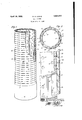
' With these preliminary observations in l 'partly in section and partly in elevation.
In the accompanying drawings the inner wall of my strainer 1s illustrated as made of ordinary well pipe; and it may composed of well pipe of any suitablethickness and selected size. This well pipe is .used in standard lengths, the lengths being joined Atogether by the usual screw-threaded collars 11, one at the end of each length. To form I ny screen, a length of well pipe is provided Vwith openings 12 which may be formed in any suitable manner, as by punching or drilling or slotting; but they are here shown preferably as round holes such as may be easily punched or drilled. To suit the specific form of my invention wherein longitudinal spacing ribs are used, these holes are preferably arranged in longitudinal rows, as illustrated in the drawings; but the holes in adjacent rows may be arranged in staggered relation, as is also clearly illustrated. In forming these holes 12 there are only two controlling factors to be kept in mind. First the aggregate area of the holes is sufficient to pass the total fluid flow at comparatively low velocity and without forming any appreciable obstruction to the fluid iow; and second the holes are so formed as a weaken the pipe as little as possible. Round holes suit these requirements well in proportion to their total area they weaken the pipe to a minimum degree, both as regards lon itudinal tensile strength and lateral crushing, bending or shearing strength. Placing` the holes in staggered relation also materially decreases the amount of weakening.
Around the outside of inner wall 10 are placed, in spaced relation, the longitudinal spacing ribs 15. The numberof these ribs need not necessarily be equal to the number of rows of holes 12.; but in the specific illus-l tration I show such relation. Ribs 15 ma be formed of any suitable metal, such as iron or steel. For instance they may be formed of substantially the same steel as that of the pipe. They are welded to the inner wall 10,
either continuously alon their lengths, or at least at intervals along teir lengths; so that, forall tensile strength purposes, they become integral parts of the inner wall, and are s'o illustrated in the drawings.
These ribs 15 are of uniform thickness so that the outer strainer walls 20 may be laced about these ribs and contact withA all o them throughout their lengths. The irela'tive'sizes of inner wall, ribs and outer wall arepreferably such that the outer wallmay be heatshrunk upon the ribs to surround the ribsA snugly and tightly; but at the same time the shrink is not forcible enough to draw the outer wall out of its true circular shape. The structure thus assembled becomes, foi-all physical purposes, a single integral structure, especially so far as tensile strength and lateralstrength are concerned. The shrunk grip of the outer wall upon the ribs is suicient to keep the outer wall from sliding longitudinally under any forces imposed upon the strainer pipe; but, in practical manufacture of the Screen I weld the outer wall to one of the ribs. This may be done by closing the seam weld of the outer wall directly over a rib, thus joining the outer wall to a rib and thus to the inner wall. And I also preferably close The. outer wall 20 is 'preferably provided with a series of rows of straining slots 22 which have their lengths arranged horizontally or circumferentially of the pipe. These slots are of limited individual lengths, being only as long as the clear distance between adjacent ribs 15. The assembly is made so that a row of slots 22 will register directly with the space between adjacent ribs, and the webs 23, between adjacent rows of slots 22, will register with and rest upon the ribs 15. The longitudinally extending webs 23 of the outer wall, and the longitudinal ribs 15, together add more tensile strength to the pipe structure than has been taken away from pipe 10 by the perforations 12. In-fact, in a typical practical design, the tensile strength of the complete structure is about 25 per cent greater than the tensile strength of the unperforv ated pipe 10. And this is true in spite of the fact that horizontal slots 22 are used. And the outer wall 20 also adds materially to 'the lateral strength of the pipe as re ards crushing, bending or shearing forces. a typical average design the lateral strength of the complete assembly is about 25 per cent greater than the lateral strength of the corresponding unperforated pipe 10. This additive lateral strength is due primarily to the lateral strength of the outer wall 20 and to the fact that the outer wall fits vclosely and tightly 4around the spacers or ribs, but is at all times maintained in perfect circular formation. The shrunk fit of the outer wall upon the ribs is tight enough to accomplish the purposes described; but the shrink vis never made enough to draw the portions of wall 20 ber.
iio.
iis
isc
The size and number of slots 22 may be made as desired. I prefer to make the slots not too long so that the webs 23 of the outer wall are not separated too far. In a typical instance slots 22 may be about one-eighth of an inch wide and about one inch to one inch and a qua-rter long; and their typical vertical spacing may be about an inch. And the webs 23 may be about three-eighths'of an inch wide. Using such slots at such spacings, and such reinforced construction, I give to a length of pipe about ten times the total screeningY area that can be obtained by slotting openings in the pipe itself, and I still retain all of the original strength of the well casing, in fact increase its strength as much as 25%.
The perforations 12 may be individually of any suitable size, but the aggregate area of these perforations is preferably about the same as the aggregate area of slots 22. The aggregate area of perforations 12 is preferably not materially less than that of slots 22, so that, the fluid having once passed the straining slots, its passage will not be materially obstructed by perforations 12. But each individual opening 12 is preferably of much larger dimension than the width of a slot 22 so as to readily pass anything which a slot 22 may pass. Slots 22 may be made of any desired form, for instance they may be of constant widththroughout the thickness of wall 20, or they may be wider at the inner face of the wall than at the outer face.
Due to the comparatively large screening area in my assembly, the fluid passes comparatively slowly and quietly through the straining slots and thence into the passage spaces 30 between the two walls and between adjacent ribs l5. Here the velocity of flow is further reduced, due to the fact that the space through passage 30 is much larger than slots -22. Then the fluid flows indiscriminately through any and all of the perforations 12 which communicate with the several passages 30. The flow through the straining slots is so slow that the coarse material is left behind as the Huid passes the slots. The straining functions of the slots are not due primarily, or at least not exclusively, to the fact that the solid material may be of such size that it cannot pass through the slots 22. The slots are placed horizontally so that the coarse solid material will pile up at the lower edge of the slot rather than pass through.
Ebr instance the Vertical width of a slot v22 may be, in a typical instance, not more than the thickness of the outer wall 20; so as to form a shelf on which the coarser of suspended solid material will pile up. The very on their shelving bottoms, due to the extremely low vvelocity through the slots, and remains there. This action, it will now be seen, is due to the large number of large horizontal slots that cause separation, not by straining through small and easily clogged openings, but by reduction of velocity.
I claim:
A double tube well screen having annularly spaced inner and outer tubes, circumferentially spaced ribs attached rigidly to the outer surface of the inner tube and extending longitudinally substantially the entire length of the inner tube, the inner tube having vertically spaced perfor'ations registering with the spa-ces between ribs, the outer tube fitting tightly and directly about the ribs and having circumferentially spaced longitudinal rows of longitudinally spaced narrow circumferential slots, the rows of slots registering with the vertically extending spaces between ribs and the intervening unslotted portions of the outer tube resting directly on the ribs.
In witness that I claim the foregoing I have hereunto subscribed my name this 12th day of June, 1928.
OLLYN A. LAYNE.
fine material of course passes on through slots 22 and openings 12, to be removed from the well along with the fluid. But the coarscr material, although it may be small enough to pass through slots 22, is dropped at those slots
Priority Applications (1)
| Application Number | Priority Date | Filing Date | Title |
|---|---|---|---|
| US291856A US1854517A (en) | 1928-07-11 | 1928-07-11 | Well screen |
Applications Claiming Priority (1)
| Application Number | Priority Date | Filing Date | Title |
|---|---|---|---|
| US291856A US1854517A (en) | 1928-07-11 | 1928-07-11 | Well screen |
Publications (1)
| Publication Number | Publication Date |
|---|---|
| US1854517A true US1854517A (en) | 1932-04-19 |
Family
ID=23122149
Family Applications (1)
| Application Number | Title | Priority Date | Filing Date |
|---|---|---|---|
| US291856A Expired - Lifetime US1854517A (en) | 1928-07-11 | 1928-07-11 | Well screen |
Country Status (1)
| Country | Link |
|---|---|
| US (1) | US1854517A (en) |
Cited By (6)
| Publication number | Priority date | Publication date | Assignee | Title |
|---|---|---|---|---|
| US2476550A (en) * | 1945-03-02 | 1949-07-19 | Owens Illinois Glass Co | Injector for molding machines |
| US2838120A (en) * | 1953-10-29 | 1958-06-10 | Foundation Equipment Corp | Wellpoints |
| US3187567A (en) * | 1961-11-16 | 1965-06-08 | Pure Oil Co | Fluid flow indicating method and apparatus for well bores |
| US3972647A (en) * | 1974-04-12 | 1976-08-03 | Niedermeyer Karl O | Screen for intake of emergency sump pump |
| US20050086807A1 (en) * | 2003-10-28 | 2005-04-28 | Richard Bennett M. | Downhole screen manufacturing method |
| EP1950373A3 (en) * | 2007-01-25 | 2013-01-02 | Halliburton Energy Services, Inc. | Well screen fabrication |
-
1928
- 1928-07-11 US US291856A patent/US1854517A/en not_active Expired - Lifetime
Cited By (8)
| Publication number | Priority date | Publication date | Assignee | Title |
|---|---|---|---|---|
| US2476550A (en) * | 1945-03-02 | 1949-07-19 | Owens Illinois Glass Co | Injector for molding machines |
| US2838120A (en) * | 1953-10-29 | 1958-06-10 | Foundation Equipment Corp | Wellpoints |
| US3187567A (en) * | 1961-11-16 | 1965-06-08 | Pure Oil Co | Fluid flow indicating method and apparatus for well bores |
| US3972647A (en) * | 1974-04-12 | 1976-08-03 | Niedermeyer Karl O | Screen for intake of emergency sump pump |
| US20050086807A1 (en) * | 2003-10-28 | 2005-04-28 | Richard Bennett M. | Downhole screen manufacturing method |
| US7757401B2 (en) * | 2003-10-28 | 2010-07-20 | Baker Hughes Incorporated | Method for manufacturing a screen for downhole use |
| EP1950373A3 (en) * | 2007-01-25 | 2013-01-02 | Halliburton Energy Services, Inc. | Well screen fabrication |
| AU2008200220B2 (en) * | 2007-01-25 | 2013-03-07 | Halliburton Energy Services, Inc | Well screen fabrication |
Similar Documents
| Publication | Publication Date | Title |
|---|---|---|
| US2344909A (en) | Deep well screen | |
| US2342913A (en) | Deep well screen | |
| US6715544B2 (en) | Well screen | |
| US10450844B2 (en) | Drainage layers for sand control screen assemblies | |
| KR890003088B1 (en) | Deep well screen | |
| EA017651B1 (en) | Flow restriction device and method | |
| US1854517A (en) | Well screen | |
| US7954546B2 (en) | Subterranean screen with varying resistance to flow | |
| US2046459A (en) | Screen for oil wells | |
| GB1598502A (en) | Protected well screen | |
| US2346885A (en) | Deep well screen | |
| US1057098A (en) | Sheet-metal casing for drainage culverts, conduits, screens, &c. | |
| US1341755A (en) | Well-screen | |
| US1629018A (en) | Strainer | |
| US1165137A (en) | Double-walled strainer for culverts, drainage-casings, &c., and connecting means therefor. | |
| US1821659A (en) | Well strainer | |
| US984704A (en) | Automatic household-filter. | |
| US1643394A (en) | Perforated pipe for wells | |
| US1780882A (en) | Well screen | |
| US975333A (en) | Well-screen. | |
| US929191A (en) | Well-strainer. | |
| US787913A (en) | Strainer for oil or water wells. | |
| US895733A (en) | Oil and water well strainer. | |
| US2118171A (en) | Well screen | |
| US884048A (en) | Well-tubing. |