US1854500A - Elevator cage - Google Patents
Elevator cage Download PDFInfo
- Publication number
- US1854500A US1854500A US314189A US31418928A US1854500A US 1854500 A US1854500 A US 1854500A US 314189 A US314189 A US 314189A US 31418928 A US31418928 A US 31418928A US 1854500 A US1854500 A US 1854500A
- Authority
- US
- United States
- Prior art keywords
- cage
- car
- arm
- stops
- arms
- Prior art date
- Legal status (The legal status is an assumption and is not a legal conclusion. Google has not performed a legal analysis and makes no representation as to the accuracy of the status listed.)
- Expired - Lifetime
Links
Images

Classifications
-
- B—PERFORMING OPERATIONS; TRANSPORTING
- B66—HOISTING; LIFTING; HAULING
- B66B—ELEVATORS; ESCALATORS OR MOVING WALKWAYS
- B66B17/00—Hoistway equipment
- B66B17/14—Applications of loading and unloading equipment
- B66B17/16—Applications of loading and unloading equipment for loading and unloading mining-hoist cars or cages
- B66B17/20—Applications of loading and unloading equipment for loading and unloading mining-hoist cars or cages by moving vehicles into, or out of, the cars or cages
Definitions
- the object of my invention is to provide an elevator cage of simple, durable and inexpensive construction, of that type designed to elevate and lower carrier cars, such as used in connection with mining coal and other minerals, and to provide in connection with the cage improved means whereby a carrier car may be automatically released from'its locleed pof sition on the cage platform as the car is delivered therefrom, and to provide means for automatically locking' a second car being moved to position on said cage, and when so locked in position, the cage may be moved to its elevated position and dumped and again returned to its normal position in the bottom of the shaft, at which time the car is auto-V matically released and' a new to replace the same.
- a further object is to provide in a dumping cage improved means whereby a car may be automatically locked to said cage and retained in a locked position as the cage is operated.
- My invention consists in the construction, arrangement and combination of the various parts of the device, whereby the objects contemplated are attained, as hereinafter more car permitted fully set forth, pointed out in my claims, and illustrated' in the accompanying drawings, in j 30 which:
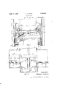
- Figure 1 is a plan view of the bottom portion of a cage showing my improved locking mechanism applied thereto, a portion ofthe top of the cage platform broken away.
- Figure 2 is a transverse sectional viewA taken on the line 2 2 of Figure 1.
- Figure 3 is a sectional view taken on the' ⁇ line 3-3 of Figure 1.
- FIG. 4 is a side elevation of m im roved v :n Y e0 cage mounted 1n the bottom end of an elevator shaft y
- the numeral 10 indicates an elevator shaft having vertical guide members 11. The lower ends of the members 11 terminate near the bottom end of the shaft 10.
- the lower end of the shaft 10 is connected with entryways 12, one of which is provided with an inclined tra ck 13 and the other with a horizontally arranged track 14. Said tracks 13 and 14 are supported above the bottom of the shaft a ⁇ plates 23 for reinforcing said flanges,
- the numeral 10 indicates an elevator shaft having vertical guide members 11.
- the lower ends of the members 11 terminate near the bottom end of the shaft 10.
- the lower end of the shaft 10 is connected with entryways 12, one of which is provided with an inclined tra ck 13 and the other with a horizontally arranged track 14.
- Said tracks 13 and 14 are supported above the bottom of the shaft a ⁇ plates 23 for reinforcing said flanges,
- a cage 15 is slidably mounted to and between the guides 11.
- Said cage comprises a frame work 16 designe'dtosup-V port a horizontally arranged floor 17.
- the side edges of the frame 16 are'lprovided withl J5 vertically arranged channels 18 designedv to travel on the guides 11.
- the said frame 16 is pivotally connected to the channels 18 by means of pivots 19 to provide a dumping cage.
- the frame 16 is" locked to the channels 18, by mechanism ⁇ not illustrated which is o f the ordinary construction and forms no part of my present invention, so that as the channels are elevated and lowered, the frame 16 will also be ele# 5 vatedand lowered.l
- the upper ends of the channels 18 are connected to the upper endY of the cage in the usual manner.
- the floor 17 is supported by horizontalj beams 20 and 21, while the top of the lioor is provided with spaced angle irons 22.
- the outer face of each of the upwardly projectflanges Aof said 'angles is provided with upper edges of the flanges and the plates 23 5 are Vdesigned to form rails upon which the wheels 24 of a car 25 are supported.
- the floor 17 is of a width equal to the distance between the outer faces of the upward-A ly extending plates 23 so that spaces 26 are ⁇ v 80 provided between the plates 23 and the side members27 of the cage.
- Rotatively mounted in the central portion of the beams 20 is a shaft 28, while a shaft 29 is 4rotatively mounted in the beams 21.
- each of the said shafts 28 vand 29 is provided with a hub 30, each of said hubs having a pair of spaced arms 31 projecting from each of its opposite sides.
- each of the plates 23 Supported on the outer'face near the forward end of each of the plates 23 is a pair of outwardly extending bearings 32.
- Each pair of said bearings is designed to support a shaft 33 on which is mounted an upwardly projecting wheel stop 34.
- the lower endd of each of the wheel stopsl 34 is provided with a downwardly extending arm 35, the lower end of each of said arms 35 having one end of a link 36 connected thereto, while the opposite ends of the links 36 are connected to and between the outer ends of the arms 31.
- the wheel stops 34 are designed to be supported normally in an upright position in alinement with the wheels 24, and in front of the front wheels 24.
- the rear ends of the outer surfaces of the plates 33 are provided with spaced brackets 37, which are designed to support shafts 38, each of the shafts being provided with an upwardly extending wheel stop 39 having downwardly extending/'arms 40.
- TheA lower ends of said arms are pivotally connected to links 41, which in turn are connected toiarms ⁇ 42 mounted on the inn-er end of the shaft 29.
- the links 41 andthe arms42l are similar to the links 36 and the arms 3l.
- Each of the stops 39 is slid'ably mounted on the shafts 38 and are yiel'dably held to their forward limit of movement by means of springs 43.
- the said stops 39 are designed to ⁇ engage the rear sides of the rear wheels 24 when Vin their normal upright positions.
- the forward end of the shaft 28 is provided with a lever 45,y while the rear end of the shaft 29 is provi-.ded with a lever 46. Both of said levers 45 and 46 extend toward the the same side of the device, and have their free ends inclined downwardly and outwardly, as-illustrated by dotted lines in Figure 3, whenI the stops 34 and 39 are in an upright position. l
- each bracket 47 is provided with an upwardly extending trip arm 48, while the other bracket 47 is provided with an upwardly extend-ing trip arm 49.
- the upper end of each of the trip arms provided with a laterally extending plate 50.
- the lower ends of each of the arms 48 and 49 have an inwardly extending weight 51 which normally supports the upper ends off the arms 48 and 49 to a position slightly inclined inwardly from a vertical line.
- the outer ends ofthe arms 51 are designed to rest on the base of the bracket 47 when the arms are in the said position.
- the upper ends of said arms are located immediately below the free ends of the arms 45 andv 46 so that as the cage platform is lowered in the shaft, the free ends ofthe arms 45 and 46 will engage the upper ends of the arms 48 and 49, and cause the shafts 28 and 29 to be rotated and the upper ends of 'the wheel stops 34 and ⁇ 39 to be moved outwardly.
- a bell crank lever 53 Pivotally connected to the left hand plate 23, as shown in Figure 2, is a bell crank lever 53 having one arm 54 projecting slightly above the plate23 and tho other arm projecting downwardly, the lower end of which is pivotally connected to one end of a trip bar 54a, the free end of which is slidably mounted in a slot 55 in the end plate 56a.
- the free end ⁇ of said bar 54a is adapted to swing to an inclined position, shown by dotted lines in Fig. 2.
- the plate 23 is also provided. with a bell crank lever 56 having an arm 57 designed to rest slightly above the upper edge ofthe plate 23 and a downwardly projecting arm pivotally connected to a link 58, which extends through a slot 59 in the end plate 60.
- the free end ofthe link 58 is also adapted to swing upwardly and downwardly.
- the lower ends of the arms 53 and 56 are connected by a link 61, having a spring 61a to yieldably hold the said link in its left handl position, so that the upper edge of the arm 57 will rest movably below the upper edge ofthe plate 23 with the arm 54 above said plate.
- the outer end of the bar 54a is designed to rest on the upper edge of the plates 50 of the arm 48 as shown by dotted lines inV Figure 2, while the free end of the. link 58 is designed to rest adjacent to the front face of the plate 50 ofthe arm 49, when the cage is at its lower limit of movement.
- rl ⁇ he bar 54a will also be moved to the right, causing its free end to disengage the upper edge of the plate 50, and to drop into position adjacent to the back face of said plate, as shown by solid lines in Figure 2.
- the lower end of the arm 56 will also be moved to the right, causing the upper edge of the arm 57 to be elevated above the plate 23.
- l have provided a mechanism designed to be used on elevator cages, whereby a car supported thereon will be automatically unlocked, to permit the car to be removed, and provided with means whereby a second car will be automatically locked in position through the movement of the car, as it is placed on said cage.
- rlhe springs 43 provide means whereby the shock of the momentum of the car will be greatly reduced, as the stops 39 are permitted to yield rearwardly.
- the springs are of such tension that the car will be again moved forwardly, as the shock is relieved, to position with the front side of the front wheels against the stops 34.
- the springs '43 also take up any slack movement between said stops, so that the car is firmly held against movement while the cage is in action.
- An elevator comprising a. supporting frame, a pair of spaced rails thereon, front and rear wheel stops pivotally mounted ad- -jacent to each side of said rails so that this upper ends will swing outwardly, said stops having downwardly extending levers, a pair of longitudinally extending and alined rock shafts, a rock arm carried by each of said shafts, links connected with the free ends of said rock arms and the lower ends of the downwardly extending arm of said wheel stops, springs for normally retaining said wheel stops in their upper and inner limit of movement, a lever connected to the outer end of each of said rock shafts, a trip lever supported beneath the lower end of each of said levers, a pair of bell crank levers pivotally connected to the outer face of one of said rails, one of said levers having a forwardly extending trip arm and the other lever having a rearwardly extending trip arm, the lower ends of said bell crank levers being connected by a link, a bar pivotally connected to the forward end of said link and supported
- An elevator comprising a supporting frame, a pair of spaced rails thereon, front and rear wheel stops pivotally mounted adjacent to each side of said rails so that their upper ends will swing outwardly, yieldable means for normally retaining said wheel stops at their upper and inner limits of movement, means for actuating said stops outwardly, said means including a pair of horizontal pivot levers, -means operatively connecting said levers with said stops, a pair of bell crank levers pivotally connected to the outer surface of one of said rails, one of said levers having a forwardly extending trip arm and the other lever having a rearwardly extending trip arm, the lower ends of said bell crank levers being connected by a link, a bar pivotally connected to the forward end of said link and supported in position to engage the forward trip lever, and a second link extending rearwardly and connected to the lower ends of said bell crank levers and designed to engage the upper end of the rear trip lever.
Landscapes
- Types And Forms Of Lifts (AREA)
Description
Filed Oct. 22,' V1928 2 Shee'cs-Sheet 1 T. ULMANN ELEVATOR CAGE April '19, 1932.
Filed Oct. 22, 1928 2 Sheets-Sheet 2 Patented Apr. 19, 1932 UNT STATES THEODORE AULMANN, OF DES MOINES, IOWA ELEVATOR CAGE Application led October 22,1928. Serial No. 314,189.
The object of my invention is to provide an elevator cage of simple, durable and inexpensive construction, of that type designed to elevate and lower carrier cars, such as used in connection with mining coal and other minerals, and to provide in connection with the cage improved means whereby a carrier car may be automatically released from'its locleed pof sition on the cage platform as the car is delivered therefrom, and to provide means for automatically locking' a second car being moved to position on said cage, and when so locked in position, the cage may be moved to its elevated position and dumped and again returned to its normal position in the bottom of the shaft, at which time the car is auto-V matically released and' a new to replace the same.
A further object is to provide in a dumping cage improved means whereby a car may be automatically locked to said cage and retained in a locked position as the cage is operated.
My invention consists in the construction, arrangement and combination of the various parts of the device, whereby the objects contemplated are attained, as hereinafter more car permitted fully set forth, pointed out in my claims, and illustrated' in the accompanying drawings, in j 30 which: A
Figure 1 isa plan view of the bottom portion of a cage showing my improved locking mechanism applied thereto, a portion ofthe top of the cage platform broken away.
Figure 2 is a transverse sectional viewA taken on the line 2 2 of Figure 1.
Figure 3 is a sectional view taken on the'` line 3-3 of Figure 1.
Figure 4 is a side elevation of m im roved v :n Y e0 cage mounted 1n the bottom end of an elevator shaft y The numeral 10 indicates an elevator shaft having vertical guide members 11. The lower ends of the members 11 terminate near the bottom end of the shaft 10. The lower end of the shaft 10 is connected with entryways 12, one of which is provided with an inclined tra ck 13 and the other with a horizontally arranged track 14. Said tracks 13 and 14 are supported above the bottom of the shaft a `plates 23 for reinforcing said flanges, The
slight distance. A cage 15 is slidably mounted to and between the guides 11. Said cage comprises a frame work 16 designe'dtosup-V port a horizontally arranged floor 17. The side edges of the frame 16 are'lprovided withl J5 vertically arranged channels 18 designedv to travel on the guides 11.
' The said frame 16 is pivotally connected to the channels 18 by means of pivots 19 to provide a dumping cage. The frame 16 is" locked to the channels 18, by mechanism `not illustrated which is o f the ordinary construction and forms no part of my present invention, so that as the channels are elevated and lowered, the frame 16 will also be ele# 5 vatedand lowered.l The upper ends of the channels 18 are connected to the upper endY of the cage in the usual manner.
The floor 17 is supported by horizontalj beams 20 and 21, while the top of the lioor is provided with spaced angle irons 22. The outer face of each of the upwardly projectflanges Aof said 'angles is provided with upper edges of the flanges and the plates 23 5 are Vdesigned to form rails upon which the wheels 24 of a car 25 are supported.
The floor 17 is of a width equal to the distance between the outer faces of the upward-A ly extending plates 23 so that spaces 26 are`v 80 provided between the plates 23 and the side members27 of the cage.-
Rotatively mounted in the central portion of the beams 20 is a shaft 28, while a shaft 29 is 4rotatively mounted in the beams 21. The
` inner' end of each of the said shafts 28 vand 29 is provided with a hub 30, each of said hubs having a pair of spaced arms 31 projecting from each of its opposite sides.
Supported on the outer'face near the forward end of each of the plates 23 is a pair of outwardly extending bearings 32. Each pair of said bearings is designed to support a shaft 33 on which is mounted an upwardly projecting wheel stop 34. The lower endd of each of the wheel stopsl 34 is provided with a downwardly extending arm 35, the lower end of each of said arms 35 having one end of a link 36 connected thereto, while the opposite ends of the links 36 are connected to and between the outer ends of the arms 31. The wheel stops 34 are designed to be supported normally in an upright position in alinement with the wheels 24, and in front of the front wheels 24.
The rear ends of the outer surfaces of the plates 33 are provided with spaced brackets 37, which are designed to support shafts 38, each of the shafts being provided with an upwardly extending wheel stop 39 having downwardly extending/'arms 40. TheA lower ends of said arms are pivotally connected to links 41, which in turn are connected toiarms `42 mounted on the inn-er end of the shaft 29. The links 41 andthe arms42l are similar to the links 36 and the arms 3l. Each of the stops 39 is slid'ably mounted on the shafts 38 and are yiel'dably held to their forward limit of movement by means of springs 43. The said stops 39 are designed to` engage the rear sides of the rear wheels 24 when Vin their normal upright positions.
lt will readilybe seen that iff the shafts 28 and 29 are rocked in a clockwise direction, as illustrated in Figure 3, the free ends of the arms 31 'and 42 will be rotated@ in a clockwise direction, causingthe links 36 and 41 to be moved inwardly, which in turn will cause the upper ends. of the wheell stops 34 and 39 to be moved outwardly out ofthe path of the wheels 24. Springs 44 are provided for normally retaining the stops 34 and 39 at their inner limit ofV movement..
The forward end of the shaft 28 is provided with a lever 45,y while the rear end of the shaft 29 is provi-.ded with a lever 46. Both of said levers 45 and 46 extend toward the the same side of the device, and have their free ends inclined downwardly and outwardly, as-illustrated by dotted lines in Figure 3, whenI the stops 34 and 39 are in an upright position. l
Supported in the bottom of the shaft 10 is a. pair ofbrackets 47 one of said brackets being provided with an upwardly extending trip arm 48, while the other bracket 47 is provided with an upwardly extend-ing trip arm 49. The upper end of each of the trip arms provided with a laterally extending plate 50. The lower ends of each of the arms 48 and 49 have an inwardly extending weight 51 which normally supports the upper ends off the arms 48 and 49 to a position slightly inclined inwardly from a vertical line. The outer ends ofthe arms 51 are designed to rest on the base of the bracket 47 when the arms are in the said position.
The upper ends of said arms are located immediately below the free ends of the arms 45 andv 46 so that as the cage platform is lowered in the shaft, the free ends ofthe arms 45 and 46 will engage the upper ends of the arms 48 and 49, and cause the shafts 28 and 29 to be rotated and the upper ends of 'the wheel stops 34 and`39 to be moved outwardly.
The upper ends of said stops are moved out of the path of the wheels at the time the cage has reached its downward limit of movement.
Pivotally connected to the left hand plate 23, as shown in Figure 2, is a bell crank lever 53 having one arm 54 projecting slightly above the plate23 and tho other arm projecting downwardly, the lower end of which is pivotally connected to one end of a trip bar 54a, the free end of which is slidably mounted in a slot 55 in the end plate 56a. The free end` of said bar 54a is adapted to swing to an inclined position, shown by dotted lines in Fig. 2.
The plate 23 is also provided. with a bell crank lever 56 having an arm 57 designed to rest slightly above the upper edge ofthe plate 23 and a downwardly projecting arm pivotally connected to a link 58, which extends through a slot 59 in the end plate 60. The free end ofthe link 58 is also adapted to swing upwardly and downwardly. The lower ends of the arms 53 and 56 are connected by a link 61, having a spring 61a to yieldably hold the said link in its left handl position, so that the upper edge of the arm 57 will rest movably below the upper edge ofthe plate 23 with the arm 54 above said plate.
The outer end of the bar 54a is designed to rest on the upper edge of the plates 50 of the arm 48 as shown by dotted lines inV Figure 2, while the free end of the. link 58 is designed to rest adjacent to the front face of the plate 50 ofthe arm 49, when the cage is at its lower limit of movement.
rThe operation of my device is as follows: Alssuming that the wheels of the ear 25 are supported on the rails 22 between the wheel stops 34 and 39, and that the cage is being, lowered in the shaft, the free ends of the arms 45 and 46 will engage the upper ends of the trip arms-48 and 49, causing the shafts 28 and 29 to herotated and the upper ends of the stops 34 and 39 moved outwardly from alinement with the wheels 24.
rlhe filled car 62 is supported on the tracks 13 vand is automatically released' by downward movement of the cage by mechanism not illustrated, so that the rear end of the ear 62 willl engage the forward end of the car 25 and push the car 25 rearwardly to the track 14. The car 62l is moved by gravity. As the rear wheels of the car 62. engage 'the arm 54, the lower end of the lever 53 will be moved' to the right, as shown in Figure 2, which in turn will move the links 6l and 58, causing the trip arm 49l to be moved rearwardly from under the arm 46. rl`he bar 54a will also be moved to the right, causing its free end to disengage the upper edge of the plate 50, and to drop into position adjacent to the back face of said plate, as shown by solid lines in Figure 2. The lower end of the arm 56 will also be moved to the right, causing the upper edge of the arm 57 to be elevated above the plate 23.
rlhe free end of the arm 46 is then moved downwardly to its inclined position by means of the spring 44, and at the same time causing the upper ends of the stops 39 to return to their normal upright position in alinement with the oack wheels of the car 62. Said stops stop the car against further movement, as the car 62 is moved rearwardly, at which time the rear wheels will enga-ge the upper edge of the lever 57, causing the lower end of the arm 56 to be moved to the left, as shown in Figure 2, which in turn will move the upper end of the trip arm 48 forwardly to disengage the lower end of the lever 45, which will permit the shaft 28 to be rotated and the upper ends of the stops 34 moved into position in frontof the front wheels of the car 62, and thereby lock the said car to a central position on the cage platform, until the cage has been elevated and the car dumped and again returned to its position in the bottom of the shaft, at which time the above operation is repeated. As the lower end of the arm 5S is moved to the left, the lever 53 will be operated and the arm 54 elevated.
rThus it will be seen that l have provided a mechanism designed to be used on elevator cages, whereby a car supported thereon will be automatically unlocked, to permit the car to be removed, and provided with means whereby a second car will be automatically locked in position through the movement of the car, as it is placed on said cage.
rlhe springs 43 provide means whereby the shock of the momentum of the car will be greatly reduced, as the stops 39 are permitted to yield rearwardly. The springs are of such tension that the car will be again moved forwardly, as the shock is relieved, to position with the front side of the front wheels against the stops 34.
IThe springs '43 also take up any slack movement between said stops, so that the car is firmly held against movement while the cage is in action.
I claim as my invention:
l. An elevator comprising a. supporting frame, a pair of spaced rails thereon, front and rear wheel stops pivotally mounted ad- -jacent to each side of said rails so that this upper ends will swing outwardly, said stops having downwardly extending levers, a pair of longitudinally extending and alined rock shafts, a rock arm carried by each of said shafts, links connected with the free ends of said rock arms and the lower ends of the downwardly extending arm of said wheel stops, springs for normally retaining said wheel stops in their upper and inner limit of movement, a lever connected to the outer end of each of said rock shafts, a trip lever supported beneath the lower end of each of said levers, a pair of bell crank levers pivotally connected to the outer face of one of said rails, one of said levers having a forwardly extending trip arm and the other lever having a rearwardly extending trip arm, the lower ends of said bell crank levers being connected by a link, a bar pivotally connected to the forward end of said link and supported in position to engage the forward trip lever, and a second link extending rearwardly and connected to the lower ends of said bell crank levers and designed to engage the upper end of the rear trip lever.
2. An elevator comprising a supporting frame, a pair of spaced rails thereon, front and rear wheel stops pivotally mounted adjacent to each side of said rails so that their upper ends will swing outwardly, yieldable means for normally retaining said wheel stops at their upper and inner limits of movement, means for actuating said stops outwardly, said means including a pair of horizontal pivot levers, -means operatively connecting said levers with said stops, a pair of bell crank levers pivotally connected to the outer surface of one of said rails, one of said levers having a forwardly extending trip arm and the other lever having a rearwardly extending trip arm, the lower ends of said bell crank levers being connected by a link, a bar pivotally connected to the forward end of said link and supported in position to engage the forward trip lever, and a second link extending rearwardly and connected to the lower ends of said bell crank levers and designed to engage the upper end of the rear trip lever.
Des Moines, Iowa, August 3, 1928.
THEODORE AULMANN.
Priority Applications (1)
| Application Number | Priority Date | Filing Date | Title |
|---|---|---|---|
| US314189A US1854500A (en) | 1928-10-22 | 1928-10-22 | Elevator cage |
Applications Claiming Priority (1)
| Application Number | Priority Date | Filing Date | Title |
|---|---|---|---|
| US314189A US1854500A (en) | 1928-10-22 | 1928-10-22 | Elevator cage |
Publications (1)
| Publication Number | Publication Date |
|---|---|
| US1854500A true US1854500A (en) | 1932-04-19 |
Family
ID=23218937
Family Applications (1)
| Application Number | Title | Priority Date | Filing Date |
|---|---|---|---|
| US314189A Expired - Lifetime US1854500A (en) | 1928-10-22 | 1928-10-22 | Elevator cage |
Country Status (1)
| Country | Link |
|---|---|
| US (1) | US1854500A (en) |
Cited By (1)
| Publication number | Priority date | Publication date | Assignee | Title |
|---|---|---|---|---|
| FR2339553A1 (en) * | 1976-01-31 | 1977-08-26 | Stierlen Maquet Ag | LOADING AND UNLOADING STATION FOR HANDLING INSTALLATION |
-
1928
- 1928-10-22 US US314189A patent/US1854500A/en not_active Expired - Lifetime
Cited By (1)
| Publication number | Priority date | Publication date | Assignee | Title |
|---|---|---|---|---|
| FR2339553A1 (en) * | 1976-01-31 | 1977-08-26 | Stierlen Maquet Ag | LOADING AND UNLOADING STATION FOR HANDLING INSTALLATION |
Similar Documents
| Publication | Publication Date | Title |
|---|---|---|
| US1854500A (en) | Elevator cage | |
| US2822937A (en) | Shuttle car mechanism | |
| US1759757A (en) | Car-unloading device | |
| US1993203A (en) | Three-way dumping body | |
| US1786560A (en) | Dumping truck | |
| US2057833A (en) | Dumping body for automobile trucks | |
| US252055A (en) | Coal-chute | |
| US1398896A (en) | Mine-car-controlling mechanism | |
| US1744894A (en) | Lifting truck | |
| US1465661A (en) | Rotary car dump | |
| US811486A (en) | Tipple. | |
| US547309A (en) | Dumping-car | |
| US481968A (en) | Car-dumping apparatus | |
| US1408379A (en) | Turntable | |
| US519753A (en) | Dirt-loading machine | |
| US1230251A (en) | Truck. | |
| US907350A (en) | Mine-car stop. | |
| US470658A (en) | Dumping-car | |
| US982426A (en) | Mine-car-dumping apparatus. | |
| US1016302A (en) | Belt guiding and shifting device. | |
| US463006A (en) | Automatic car-dump | |
| US1200397A (en) | Sugar-beet dump. | |
| US1678569A (en) | Dump truck | |
| US1111830A (en) | Mine-car-dumping apparatus. | |
| US1403050A (en) | Motor-truck dump |