US1854499A - Window awning - Google Patents
Window awning Download PDFInfo
- Publication number
- US1854499A US1854499A US444118A US44411830A US1854499A US 1854499 A US1854499 A US 1854499A US 444118 A US444118 A US 444118A US 44411830 A US44411830 A US 44411830A US 1854499 A US1854499 A US 1854499A
- Authority
- US
- United States
- Prior art keywords
- frame
- awning
- pivoted
- window
- brace
- Prior art date
- Legal status (The legal status is an assumption and is not a legal conclusion. Google has not performed a legal analysis and makes no representation as to the accuracy of the status listed.)
- Expired - Lifetime
Links
- 239000004744 fabric Substances 0.000 description 17
- 230000000694 effects Effects 0.000 description 5
- 238000010276 construction Methods 0.000 description 3
- 238000005096 rolling process Methods 0.000 description 2
- 210000001015 abdomen Anatomy 0.000 description 1
- 230000008030 elimination Effects 0.000 description 1
- 238000003379 elimination reaction Methods 0.000 description 1
- 210000003141 lower extremity Anatomy 0.000 description 1
- 239000002184 metal Substances 0.000 description 1
Images
Classifications
-
- E—FIXED CONSTRUCTIONS
- E06—DOORS, WINDOWS, SHUTTERS, OR ROLLER BLINDS IN GENERAL; LADDERS
- E06B—FIXED OR MOVABLE CLOSURES FOR OPENINGS IN BUILDINGS, VEHICLES, FENCES OR LIKE ENCLOSURES IN GENERAL, e.g. DOORS, WINDOWS, BLINDS, GATES
- E06B9/00—Screening or protective devices for wall or similar openings, with or without operating or securing mechanisms; Closures of similar construction
- E06B9/56—Operating, guiding or securing devices or arrangements for roll-type closures; Spring drums; Tape drums; Counterweighting arrangements therefor
- E06B9/92—Means allowing the closures to be shifted out of the plane of the opening
-
- Y—GENERAL TAGGING OF NEW TECHNOLOGICAL DEVELOPMENTS; GENERAL TAGGING OF CROSS-SECTIONAL TECHNOLOGIES SPANNING OVER SEVERAL SECTIONS OF THE IPC; TECHNICAL SUBJECTS COVERED BY FORMER USPC CROSS-REFERENCE ART COLLECTIONS [XRACs] AND DIGESTS
- Y10—TECHNICAL SUBJECTS COVERED BY FORMER USPC
- Y10S—TECHNICAL SUBJECTS COVERED BY FORMER USPC CROSS-REFERENCE ART COLLECTIONS [XRACs] AND DIGESTS
- Y10S160/00—Flexible or portable closure, partition, or panel
- Y10S160/907—Spring, other than spring roller, awning operator
-
- Y—GENERAL TAGGING OF NEW TECHNOLOGICAL DEVELOPMENTS; GENERAL TAGGING OF CROSS-SECTIONAL TECHNOLOGIES SPANNING OVER SEVERAL SECTIONS OF THE IPC; TECHNICAL SUBJECTS COVERED BY FORMER USPC CROSS-REFERENCE ART COLLECTIONS [XRACs] AND DIGESTS
- Y10—TECHNICAL SUBJECTS COVERED BY FORMER USPC
- Y10S—TECHNICAL SUBJECTS COVERED BY FORMER USPC CROSS-REFERENCE ART COLLECTIONS [XRACs] AND DIGESTS
- Y10S160/00—Flexible or portable closure, partition, or panel
- Y10S160/911—Worm gear awning operator
Definitions
- This invention relates to window awnings of that class provided a visor which may be adjustably positioned anywhere throughout the height of a window opening or which may be used in vertical position as a screen or shade covering the entire height of the window or any fraction thereof, said awning being entirely operable from inside of the building.
- a further object of the invention is to provide a construction of the character aforesaid having spring or retractile means which constantly maintain the parts under tension to prevent rattling or vibration of any of the parts, both when the awning is open and when it is in its collapsed or folded condition.
- a still further object is to produce an automatic awning of the character outlined having means whereby its operation may be entirely controlled from within a building.
- Another object of the invention is to provide a combination supporting bracket and housing forming a hood or protecting housing within which the awning fabric and opera-'-.ing mechanism is entirely encased when the same is in collapsed position to obviate the necessity of removing the awning in winter and at the same time leave no nesting places for birds or the like.
- a still further object of the invention is to provide a strong, durable, eflicient, inex pensive and simple construction of the character outlined; and in order that the invention may be fully understood, reference is to be had to the accompanying drawings, in which:
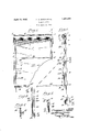
- FIG. 1 is a fragmentary front elevation of an awning embodying the invention.
- Figure 2 is a section on the line IIII of Figure 1.
- Figure 3 is a side elevation of the awning frame in folded or collapsed position.
- Figure 1 is a perspective view of one of the upper sliding bracket members.
- Figure 5 is a view similar to Figure 4, but illustrates the bracket with the upper brace member in operative relation thereto when the fabric is spread to form or provide a visor.
- brackets mounted at the top and on opposite sides of a window opening, said brackets each being of relatively right angle shape, the projecting flanges thereof having opposing grooves in their inner faces for the reception of the ends of a sheet metal hood or housing 2, as shown in Figures 1 and 2, said grooves being so arranged that the front edge of the hood is formed with a return bend 3 to stiffen or reinforce the same against vibration by the wind.
- bearing lugs 4 Projecting from the brackets 1, are bearing lugs 4, and formed integrally with said brackets at their lower ends are stops 5, all for a purpose which will hereinafter appear.
- a shaft 6' is journaled in the brackets 1, and secured to said shaft is one end of an awning fabric 7, to be wound upon and unwound from the shaft as the awning is respectively raised and lowered.
- One end of the shaft 6 is equipped with a-gear wheel 8, enmeshed with a worm 9 or other suitable gear, secured to the upper end of a vertically extending guide rod 10, it being evident that upon proper rotation of said guide rod, the awning fabric may be wound upon or unwound from the shaft 6.
- a similar non-rotatable guide rod 11 On the opposite side of the window from the guide rode 10 is a similar non-rotatable guide rod 11, it being evident, however, that the operating mechanism may be located on either side of the window.
- the rotatable guide rod 10 at its lower end, extends into a bracket 12 secured to the outside face of the conventional casing (not detailed) of the window, and within said bracket the rod is equipped with a bevel gear 13 enmeshed with a bevel gear 14 mounted on a shaft 15 extending through the casing into the building, and having its inner end equipped with a permanent or removable crank 16, whereby the guide rod may be rotated to efiect rolling or unrolling of the awning fabric, as above-described.
- brackets 17 and 18 Slidingly mounted on rods 10 and 11 are upper and lower brackets 17 and 18 respectively, arranged in pairs and connected by straps or bars 19, the brackets 17 being connected by a cross bar 20 bridging the window opening.
- the relatively inverted U-shaped frame thus formed is freely slidable from a point where its upper end may contact with the hood, to a point where brackets 18 abut sleeves 21 on rods 10 and 11.
- a relatively U-shaped awning frame 22 The ends of a relatively U-shaped awning frame 22 are pivoted to brackets 18 that it may swing from the relatively horizontal position shown in Figure 2, to the relatively vertical position shown in Figure 3, it being noted in this connection, however, that the parts are so proportioned that the frame can never swing inwardly past a vertical position as this might lead to the locking of the mechanism in closed position.
- the parts are so proportioned that the awning frame in closed position, inclines slightly outwardly so that its leverage will always insure opening of the awning when brackets 18 contact with stops or sleeves 21, although it is to be understood that if manually opening of the awning is desired the frame may be permitted to swing inwardly past the vertical, or that, in such a situation springs might be used to give the desired impetus to ensure opening movement.
- the awning fabric 7 passes under the cross bar 20 and is securely attached to the cross member of the U-shaped frame 22.
- Pivoted to the side members of frame 22 are lower brace members 23 having their upper ends pivoted to upper brace members 24, which in turn are pivoted to the upper slide brackets 17 of the inverted sliding U-frame, said brackets 17 being provided with stop members 25 to prevent the break-joint brace from swinging inwardly beyond a line passing through their centers as this would provide lost motion in the parts.
- the upper breakjoint brace members 24 are provided with'a pair of projecting lugs 26 and 27, the lower most lug 26 upon upward movement of the awning coming in contact with the stop 5 and effecting outward collapsing or breaking movement of the brace, to cause the uppermost lug 27 to override and rest on the stop 5 (see dotted lines, Figure 2) to prevent downward falling movement of the structure, so that the entire frame will be maintained adjacent the top of the window pending the folding movement of frame 22 to the position shown by Figure 3, it being noted that this adjustment brings the cross-members of the pivoted and slide frames so close together that no visor portion remains, the visor portion being that stretch of the fabric running from its lower extremity to the cross-member 20.
- the retractile spring 29 is maintaining an upward pull at one side of the pivotal point 30 and a downward push on the other side of such pivotal point, but as the fabric cannot unroll from the roller due to the enmeshed gears, the force of said spring removes lost motion from the parts and prevents rattling and vibration in the wind. It will also be apparent from a consideration of Figure 2, that gusts of wind cannot effect accidental collapse or folding of the awning, as the frame is locked in open position by the brace, assisted by springs 29; and the weight of the structure is such that it requires a considerable pressure to belly out the visor portion 31 of the fabric, and effect lifting of the entire structure.
- the entire awning frame may be drawn up until the cross bar 20 is against the lower edge of the housing 2, and the spring 29 acts to continue the collapsing movement of the brace member 24 to dispose it wholly outward of the vertical plane of stop 5.
- the operator reversely operates the shaft 6, the entire awning frame structure gravitating downwardly along the guide rods, until the weight of said frame is removed from the fabric by the stops or sleeves 21, and then the weight of the pivoted U- frame overcomes the spring tension until the points of connection of the springs pass center, from which point the springs assist in the unfolding operation, until the pivoted frame is locked by alinement of the breakjoint braces as heretofore stated.
- the awning fabric may be rolled up to position the visor at any desired point, and it can only be unlocked by being raised high enough to effect the tripping of the break-j oint brace as above recited.
- an awning the combination of fixed vertical guides, a relatively inverted U- frame vertically slidable on said guides, an awning frame pivotally connected to the lower ends of said U-frame and capable of opening and closing swinging movement, a collapsible brace connected at one end to said awning frame and at its upper end to said U-frame, and retractile means exerting yieldingly-applied force upon the brace and pivoted frame tending to hold the pivoted awning frame in either open or closed position.
- an awning the combination of fixed vertical guides, a relatively inverted U-frame vertically slidable on said guides, an awning frame pivotally connected to the lower ends of said U-frame and capable of opening and closing swinging movement, a collapsible brace connected at one end to said Uframe and at its other end to said awning frame, a retractile spring connecting the awning frame and the brace and tending to hold the former in open or closed position, and means for collapsing said brace outwardly when the slidable frame has nearly attained its upward limit of movement.
- an awning In an awning the combination of fixed vertical guides, a relatively inverted U-frame vertically slidable on said guides, an awning frame pivotally connected to the lower ends of said U-frame, a collapsible brace connected at one end to the said awning frame and at its other end to said U-frame, and retractile means connected to said collapsible brace, the retractile means having its lower end secured to the awning frame at such a point that it passes from one side to the other of the pivotal point of said frame to the inverted U-frame whereby the retractile means tends to maintain the awning open or closed depending upon whether said awning frame is in open or closed position.
- awning comprising vertical guide rods at opposite sides of a'window, an inverted vertically-slidable frame spanning the window, a U-frame pivoted to the lower end of the first-named frame and also spanning the window and adapt-ed to occupy a horizontal or open position or an upright or folded position, awning fabric extending from the upper end of the window and attached at its lower end to the cross-member of the pivoted frame and extending through the first-named frame and engaging the inner side of the cross-member thereof, braces composed of two members pivoted together and respectively pivoted to the pivoted frame near the pivoted end thereof and to the firstnamed frame near the upper end thereof,
- An awning comprising vertical guide rods at opposite sides of a window, an inverted vertically-slidable U-frame spanning the window, a U-frame pivoted to the lower end of the first-named frame and also spanning the window and adapted to occupy a horizontal or open positionor an upright or folded position, awning fabric extending from the upper end of the window and attached at its lower end to the cross-member of the pivoted frame and extending through the first-named frame and engaging the inner side of the cross-member thereof, braces composed of two members pivoted together and respectively pivoted to the pivoted frame near the pivoted end thereof and to the first-named frame near the upper end thereof, springs connected to the lower members of the braces and to the first-named frame and adapted when the pivoted frame is in open position to exert force to hold said frame open and to pull the braces downward and inward toward the window, means for limiting movement of the upper ends of the lower members of the braces toward the window under the force exerted by said springs, and means for causing
- An awning comprising vertical guide rods at opposite sides of a window, an inverted vertically-slidable frame spanning the window, a U-frame pivoted to the lower end of the first-named frame and also spanning the window and adapted to occupy a horizontal or open position.
- awning fabric extending from the upper end of the window and attached at its lower end to the cross-member of the pivoted frame and extending through the firstnamed frame and engaging the inner side of the cross-member thereof
- braces composed of two members pivoted together and respectively pivoted to the pivoted frame near the pivoted end thereof and to the first-named frame near the upper end thereof
- springs connected to the lower members of the braces and to the first-named frame and adapted when the pivoted frame is in open position to exert force to hold said frame open and to I pull the braces downward and inward toward the window
- means for limiting movement of the upper ends of the lower members of the braces toward the window under the force exerted by said springs means for causing the fabric to exert an upward pull on the cross-member of the pivoted frame to effect upward movement of the slide frame without effecting collapsing or folding movement of the pivoted frame, and means for engagement by the upper member of the brace as the upward sliding movement of the first-named frame is nearly completed, to collapse
Landscapes
- Engineering & Computer Science (AREA)
- Structural Engineering (AREA)
- Architecture (AREA)
- Civil Engineering (AREA)
- Building Awnings And Sunshades (AREA)
Description
April l9, 1932. F. A. ANTON ET AL WINDOW AWNING Filed April 14, 1930 Zmoentors made I .AIZFQ v zfiwwzweza Patented Apr. 19, 1932 UNITE STATES,
PATENT, FFICE FREDERICK A. ANTON AND EDWIN F. BELL, F TOPEKA, KANSAS, ASSIGNORS T0 TOPEKA Li TENT & AWNING COMPANY, OF TOPEKA, KANSAS, A CORPORATION OF KANSAS WINDOW Application filed April 14,
This invention relates to window awnings of that class provided a visor which may be adjustably positioned anywhere throughout the height of a window opening or which may be used in vertical position as a screen or shade covering the entire height of the window or any fraction thereof, said awning being entirely operable from inside of the building.
A further object of the invention is to provide a construction of the character aforesaid having spring or retractile means which constantly maintain the parts under tension to prevent rattling or vibration of any of the parts, both when the awning is open and when it is in its collapsed or folded condition.
A still further object is to produce an automatic awning of the character outlined having means whereby its operation may be entirely controlled from within a building.
Another object of the invention is to provide a combination supporting bracket and housing forming a hood or protecting housing within which the awning fabric and opera-'-.ing mechanism is entirely encased when the same is in collapsed position to obviate the necessity of removing the awning in winter and at the same time leave no nesting places for birds or the like.
A still further object of the invention is to provide a strong, durable, eflicient, inex pensive and simple construction of the character outlined; and in order that the invention may be fully understood, reference is to be had to the accompanying drawings, in which:
Figure 1 is a fragmentary front elevation of an awning embodying the invention.
Figure 2 is a section on the line IIII of Figure 1.
Figure 3 is a side elevation of the awning frame in folded or collapsed position.
Figure 1 is a perspective view of one of the upper sliding bracket members.
Figure 5 is a view similar to Figure 4, but illustrates the bracket with the upper brace member in operative relation thereto when the fabric is spread to form or provide a visor. I V
In the said drawings, where like reference AWNING 1930. Serial No. 444,118.
characters identify corresponding parts in allof the figures, 1 indicates similar bracket members mounted at the top and on opposite sides of a window opening, said brackets each being of relatively right angle shape, the projecting flanges thereof having opposing grooves in their inner faces for the reception of the ends of a sheet metal hood or housing 2, as shown in Figures 1 and 2, said grooves being so arranged that the front edge of the hood is formed with a return bend 3 to stiffen or reinforce the same against vibration by the wind. Projecting from the brackets 1, are bearing lugs 4, and formed integrally with said brackets at their lower ends are stops 5, all for a purpose which will hereinafter appear.
The opposite ends of a shaft 6'are journaled in the brackets 1, and secured to said shaft is one end of an awning fabric 7, to be wound upon and unwound from the shaft as the awning is respectively raised and lowered. One end of the shaft 6 is equipped with a-gear wheel 8, enmeshed with a worm 9 or other suitable gear, secured to the upper end of a vertically extending guide rod 10, it being evident that upon proper rotation of said guide rod, the awning fabric may be wound upon or unwound from the shaft 6. On the opposite side of the window from the guide rode 10 is a similar non-rotatable guide rod 11, it being evident, however, that the operating mechanism may be located on either side of the window. The rotatable guide rod 10 at its lower end, extends into a bracket 12 secured to the outside face of the conventional casing (not detailed) of the window, and within said bracket the rod is equipped with a bevel gear 13 enmeshed with a bevel gear 14 mounted on a shaft 15 extending through the casing into the building, and having its inner end equipped with a permanent or removable crank 16, whereby the guide rod may be rotated to efiect rolling or unrolling of the awning fabric, as above-described.
Slidingly mounted on rods 10 and 11 are upper and lower brackets 17 and 18 respectively, arranged in pairs and connected by straps or bars 19, the brackets 17 being connected by a cross bar 20 bridging the window opening. The relatively inverted U-shaped frame thus formed is freely slidable from a point where its upper end may contact with the hood, to a point where brackets 18 abut sleeves 21 on rods 10 and 11.
The ends of a relatively U-shaped awning frame 22 are pivoted to brackets 18 that it may swing from the relatively horizontal position shown in Figure 2, to the relatively vertical position shown in Figure 3, it being noted in this connection, however, that the parts are so proportioned that the frame can never swing inwardly past a vertical position as this might lead to the locking of the mechanism in closed position. By preference the parts are so proportioned that the awning frame in closed position, inclines slightly outwardly so that its leverage will always insure opening of the awning when brackets 18 contact with stops or sleeves 21, although it is to be understood that if manually opening of the awning is desired the frame may be permitted to swing inwardly past the vertical, or that, in such a situation springs might be used to give the desired impetus to ensure opening movement.
The awning fabric 7 passes under the cross bar 20 and is securely attached to the cross member of the U-shaped frame 22. Pivoted to the side members of frame 22 are lower brace members 23 having their upper ends pivoted to upper brace members 24, which in turn are pivoted to the upper slide brackets 17 of the inverted sliding U-frame, said brackets 17 being provided with stop members 25 to prevent the break-joint brace from swinging inwardly beyond a line passing through their centers as this would provide lost motion in the parts. The upper breakjoint brace members 24 are provided with'a pair of projecting lugs 26 and 27, the lower most lug 26 upon upward movement of the awning coming in contact with the stop 5 and effecting outward collapsing or breaking movement of the brace, to cause the uppermost lug 27 to override and rest on the stop 5 (see dotted lines, Figure 2) to prevent downward falling movement of the structure, so that the entire frame will be maintained adjacent the top of the window pending the folding movement of frame 22 to the position shown by Figure 3, it being noted that this adjustment brings the cross-members of the pivoted and slide frames so close together that no visor portion remains, the visor portion being that stretch of the fabric running from its lower extremity to the cross-member 20.
In order to provide means for holding the movable parts of the awning frame against vibration, it has been found desirable to so construct the pivoted ends of the frame 22 as to provide a point of attachment 28 for a retractile spring 29, which point of attachment, when the awning frame is in open position,
be evident that in this type of connection,
the retractile spring 29 is maintaining an upward pull at one side of the pivotal point 30 and a downward push on the other side of such pivotal point, but as the fabric cannot unroll from the roller due to the enmeshed gears, the force of said spring removes lost motion from the parts and prevents rattling and vibration in the wind. It will also be apparent from a consideration of Figure 2, that gusts of wind cannot effect accidental collapse or folding of the awning, as the frame is locked in open position by the brace, assisted by springs 29; and the weight of the structure is such that it requires a considerable pressure to belly out the visor portion 31 of the fabric, and effect lifting of the entire structure.
hen the awning frame is in fully collapsed position as shown in Figure 3, the upper connecting point 30a of the spring 29 has moved to a position inwardly inclined from the vertical as regards the face of the building, the guide bars 10 and 11 and the lower pointof connection 28 of said spring 29, it being evident that in this position the spring tension tends to maintain the awning in collapsed position and to remove slack or lost motion which might allow vibration to be set up by the wind.
When the awning is in this folded position,
by rolling up the fabric it will be apparent that the entire awning frame may be drawn up until the cross bar 20 is against the lower edge of the housing 2, and the spring 29 acts to continue the collapsing movement of the brace member 24 to dispose it wholly outward of the vertical plane of stop 5. When it is desired to open the awning, the operator reversely operates the shaft 6, the entire awning frame structure gravitating downwardly along the guide rods, until the weight of said frame is removed from the fabric by the stops or sleeves 21, and then the weight of the pivoted U- frame overcomes the spring tension until the points of connection of the springs pass center, from which point the springs assist in the unfolding operation, until the pivoted frame is locked by alinement of the breakjoint braces as heretofore stated. After the visor is thus formed, the awning fabric may be rolled up to position the visor at any desired point, and it can only be unlocked by being raised high enough to effect the tripping of the break-j oint brace as above recited.
From the above description, it will be apparent that we have produced a window awning embodying the features of advantage set forth as desirable in the statement of the objects of the invention, and which may be modified in minor particulars without de parting from the principles of construction or from the spirit and scope of the appended claims.
7e claim:
1. In an awning, the combination of fixed vertical guides, a relatively inverted U- frame vertically slidable on said guides, an awning frame pivotally connected to the lower ends of said U-frame and capable of opening and closing swinging movement, a collapsible brace connected at one end to said awning frame and at its upper end to said U-frame, and retractile means exerting yieldingly-applied force upon the brace and pivoted frame tending to hold the pivoted awning frame in either open or closed position.
2. In an awning, the combination of fixed vertical guides, a relatively inverted U-frame vertically slidable on said guides, an awning frame pivotally connected to the lower ends of said U-frame and capable of opening and closing swinging movement, a collapsible brace connected at one end to said Uframe and at its other end to said awning frame, a retractile spring connecting the awning frame and the brace and tending to hold the former in open or closed position, and means for collapsing said brace outwardly when the slidable frame has nearly attained its upward limit of movement.
'3. In an awning the combination of fixed vertical guides, a relatively inverted U-frame vertically slidable on said guides, an awning frame pivotally connected to the lower ends of said U-frame, a collapsible brace connected at one end to the said awning frame and at its other end to said U-frame, and retractile means connected to said collapsible brace, the retractile means having its lower end secured to the awning frame at such a point that it passes from one side to the other of the pivotal point of said frame to the inverted U-frame whereby the retractile means tends to maintain the awning open or closed depending upon whether said awning frame is in open or closed position.
in awning comprising vertical guide rods at opposite sides of a'window, an inverted vertically-slidable frame spanning the window, a U-frame pivoted to the lower end of the first-named frame and also spanning the window and adapt-ed to occupy a horizontal or open position or an upright or folded position, awning fabric extending from the upper end of the window and attached at its lower end to the cross-member of the pivoted frame and extending through the first-named frame and engaging the inner side of the cross-member thereof, braces composed of two members pivoted together and respectively pivoted to the pivoted frame near the pivoted end thereof and to the firstnamed frame near the upper end thereof,
open and to pull the braces downward and inward toward the window, and means for limiting movement of the upper ends of the lower members of the braces toward the window under the force exerted by said springs.
5. An awning comprising vertical guide rods at opposite sides of a window, an inverted vertically-slidable U-frame spanning the window, a U-frame pivoted to the lower end of the first-named frame and also spanning the window and adapted to occupy a horizontal or open positionor an upright or folded position, awning fabric extending from the upper end of the window and attached at its lower end to the cross-member of the pivoted frame and extending through the first-named frame and engaging the inner side of the cross-member thereof, braces composed of two members pivoted together and respectively pivoted to the pivoted frame near the pivoted end thereof and to the first-named frame near the upper end thereof, springs connected to the lower members of the braces and to the first-named frame and adapted when the pivoted frame is in open position to exert force to hold said frame open and to pull the braces downward and inward toward the window, means for limiting movement of the upper ends of the lower members of the braces toward the window under the force exerted by said springs, and means for causing the fabric to exert an upward pull on the cross-member of the pivoted frame to effect upward movement of the slide frame without effecting collapsing or folding movement of the pivoted frame.
6. An awning comprising vertical guide rods at opposite sides of a window, an inverted vertically-slidable frame spanning the window, a U-frame pivoted to the lower end of the first-named frame and also spanning the window and adapted to occupy a horizontal or open position. or an upright or folded position, awning fabric extending from the upper end of the window and attached at its lower end to the cross-member of the pivoted frame and extending through the firstnamed frame and engaging the inner side of the cross-member thereof, braces composed of two members pivoted together and respectively pivoted to the pivoted frame near the pivoted end thereof and to the first-named frame near the upper end thereof, springs connected to the lower members of the braces and to the first-named frame and adapted when the pivoted frame is in open position to exert force to hold said frame open and to I pull the braces downward and inward toward the window, means for limiting movement of the upper ends of the lower members of the braces toward the window under the force exerted by said springs, means for causing the fabric to exert an upward pull on the cross-member of the pivoted frame to effect upward movement of the slide frame without effecting collapsing or folding movement of the pivoted frame, and means for engagement by the upper member of the brace as the upward sliding movement of the first-named frame is nearly completed, to collapse the break-j oint braces outwardly by rotating the upper members thereof until other parts of said members overlap and abut the said last named means, to eifect the folding of the pivoted frame and the incidental elimination of the visor.
In testimony whereof We aflix signatures.
FREDERICK A. ANTON. EDlVIN F. BELL.
Priority Applications (1)
| Application Number | Priority Date | Filing Date | Title |
|---|---|---|---|
| US444118A US1854499A (en) | 1930-04-14 | 1930-04-14 | Window awning |
Applications Claiming Priority (1)
| Application Number | Priority Date | Filing Date | Title |
|---|---|---|---|
| US444118A US1854499A (en) | 1930-04-14 | 1930-04-14 | Window awning |
Publications (1)
| Publication Number | Publication Date |
|---|---|
| US1854499A true US1854499A (en) | 1932-04-19 |
Family
ID=23763580
Family Applications (1)
| Application Number | Title | Priority Date | Filing Date |
|---|---|---|---|
| US444118A Expired - Lifetime US1854499A (en) | 1930-04-14 | 1930-04-14 | Window awning |
Country Status (1)
| Country | Link |
|---|---|
| US (1) | US1854499A (en) |
Cited By (4)
| Publication number | Priority date | Publication date | Assignee | Title |
|---|---|---|---|---|
| NL1002740C2 (en) * | 1996-03-29 | 1997-09-30 | Mado Nederland | Sunshade. |
| US6095221A (en) * | 1998-08-20 | 2000-08-01 | White Consolidated Industries, Inc. | Awning extension and retraction mechanism |
| US6273172B1 (en) * | 1998-08-20 | 2001-08-14 | White Consolidated Industries, Inc. | Motor operated awning |
| US8113259B2 (en) * | 2010-06-18 | 2012-02-14 | Marvin Carl Tessmer | Side shade for an awning |
-
1930
- 1930-04-14 US US444118A patent/US1854499A/en not_active Expired - Lifetime
Cited By (7)
| Publication number | Priority date | Publication date | Assignee | Title |
|---|---|---|---|---|
| NL1002740C2 (en) * | 1996-03-29 | 1997-09-30 | Mado Nederland | Sunshade. |
| EP0798442A1 (en) * | 1996-03-29 | 1997-10-01 | Mado Nederland B.V. | A sunshade |
| US6095221A (en) * | 1998-08-20 | 2000-08-01 | White Consolidated Industries, Inc. | Awning extension and retraction mechanism |
| US6230783B1 (en) | 1998-08-20 | 2001-05-15 | White Consolidated Industries, Inc. | Awning extension and retraction mechanism |
| US6273172B1 (en) * | 1998-08-20 | 2001-08-14 | White Consolidated Industries, Inc. | Motor operated awning |
| US6276424B1 (en) | 1998-08-20 | 2001-08-21 | White Consolidated Industries, Inc. | Awning extension and retraction mechanism |
| US8113259B2 (en) * | 2010-06-18 | 2012-02-14 | Marvin Carl Tessmer | Side shade for an awning |
Similar Documents
| Publication | Publication Date | Title |
|---|---|---|
| US1854499A (en) | Window awning | |
| US2079073A (en) | Disappearing awning arms | |
| US1677230A (en) | Rolling window screen | |
| US924951A (en) | Awning. | |
| US2564641A (en) | Awning | |
| US1842598A (en) | Awning | |
| JP3070164B2 (en) | Projection screen equipment | |
| US2004674A (en) | Closure forming awning | |
| US1005584A (en) | Shutter. | |
| US1666657A (en) | Collapsible metal awning | |
| US2056341A (en) | Roll window screen and brace | |
| BE1006486A3 (en) | Improved roller awning | |
| US2169157A (en) | Shutter | |
| US1804798A (en) | Rolling awning | |
| US1225917A (en) | Folding sunshade and tent. | |
| US2253843A (en) | Awning | |
| US1597632A (en) | Awning | |
| US2129555A (en) | Automatic visor awning | |
| US1740586A (en) | Window attachment | |
| US1183112A (en) | Awning. | |
| DE220592C (en) | ||
| CN212950069U (en) | Automatic car sunshade screen of locking | |
| US1567914A (en) | Shade hanging and operating means | |
| US1805223A (en) | Awning | |
| US1243988A (en) | Awning. |