US1854493A - Sheet glass surfacing apparatus - Google Patents
Sheet glass surfacing apparatus Download PDFInfo
- Publication number
- US1854493A US1854493A US144667A US14466726A US1854493A US 1854493 A US1854493 A US 1854493A US 144667 A US144667 A US 144667A US 14466726 A US14466726 A US 14466726A US 1854493 A US1854493 A US 1854493A
- Authority
- US
- United States
- Prior art keywords
- surfacing
- arms
- supporting
- glass
- unit
- Prior art date
- Legal status (The legal status is an assumption and is not a legal conclusion. Google has not performed a legal analysis and makes no representation as to the accuracy of the status listed.)
- Expired - Lifetime
Links
- 239000005357 flat glass Substances 0.000 title description 5
- 230000008093 supporting effect Effects 0.000 description 24
- 239000011521 glass Substances 0.000 description 14
- 230000033001 locomotion Effects 0.000 description 5
- 230000006835 compression Effects 0.000 description 4
- 238000007906 compression Methods 0.000 description 4
- 238000010276 construction Methods 0.000 description 2
- 210000000887 face Anatomy 0.000 description 2
- 230000008878 coupling Effects 0.000 description 1
- 238000010168 coupling process Methods 0.000 description 1
- 238000005859 coupling reaction Methods 0.000 description 1
- 210000005069 ears Anatomy 0.000 description 1
- 230000000694 effects Effects 0.000 description 1
- 210000003128 head Anatomy 0.000 description 1
- 238000000034 method Methods 0.000 description 1
- 238000012856 packing Methods 0.000 description 1
- 238000005498 polishing Methods 0.000 description 1
- 230000000284 resting effect Effects 0.000 description 1
- 239000000725 suspension Substances 0.000 description 1
Images

Classifications
-
- B—PERFORMING OPERATIONS; TRANSPORTING
- B24—GRINDING; POLISHING
- B24B—MACHINES, DEVICES, OR PROCESSES FOR GRINDING OR POLISHING; DRESSING OR CONDITIONING OF ABRADING SURFACES; FEEDING OF GRINDING, POLISHING, OR LAPPING AGENTS
- B24B7/00—Machines or devices designed for grinding plane surfaces on work, including polishing plane glass surfaces; Accessories therefor
- B24B7/20—Machines or devices designed for grinding plane surfaces on work, including polishing plane glass surfaces; Accessories therefor characterised by a special design with respect to properties of the material of non-metallic articles to be ground
- B24B7/22—Machines or devices designed for grinding plane surfaces on work, including polishing plane glass surfaces; Accessories therefor characterised by a special design with respect to properties of the material of non-metallic articles to be ground for grinding inorganic material, e.g. stone, ceramics, porcelain
- B24B7/24—Machines or devices designed for grinding plane surfaces on work, including polishing plane glass surfaces; Accessories therefor characterised by a special design with respect to properties of the material of non-metallic articles to be ground for grinding inorganic material, e.g. stone, ceramics, porcelain for grinding or polishing glass
- B24B7/242—Machines or devices designed for grinding plane surfaces on work, including polishing plane glass surfaces; Accessories therefor characterised by a special design with respect to properties of the material of non-metallic articles to be ground for grinding inorganic material, e.g. stone, ceramics, porcelain for grinding or polishing glass for plate glass
Definitions
- the primary purpose of the present invention is to, provide improvedapparatus for supporting a: surfacing unit in such a manner that sheets of glass to be surfaced, supported upon trucks or tables, may be passed therebeneath.
- Another object of the invention is to provide improved supporting apparatus of the above;character including means for raising and lowering the surfacing unit relative to the glass sheets in an easy and convenient manner.
- Afurther object of the invention isto provide means for preventing lateral swinging movement of the-surfacing unit with respect to the glass during theraising'and lowering thereof.
- Afurther object of the invention is the provision of meansfor yieldably supporting the surfacing unit whereby to -permit free vertical sliding movement thereof.
- A. stillfurther object of the invention is to provide means for allowingmovement of the surfacing unit in a. vertical direction. and for reventingany lateral movement thereof.
- Still another object of the invention isthe provision of means for raising and lower ng the surfacing unit perpendicularly relative to the glass being surfaced wlthout changing the perpendicular axis of rotation of saidunit.
- Fig. 1 is a front elevation partially. in section, of'improved sheet glass surfacing apparatus constructed in accordance with the present invention
- Fig. 2 is a top plan view thereof partially broken away
- Fig. 3 is atransversesection. taken on line 3;3. of Fig.1,
- Fig. 4 is a side elevation of the upper portionof the supporting apparatus
- Fig. 5 is a rear view thereof
- Flg. 6 is a section showing a slightly modified-form of the present invention.
- Fig. 7 is a detail elevation showing a somewhat modified type of means for guiding the lower end of the surfacing unit
- Fig. 8- is a top plan view of the modified type of guiding means shown in Fig. 5.
- a conventional type of grinding machine designated in its entirety by the nu meral 10, and including a casing 11 in which is journaled a runner spindle 12 driven from a motor 13through the intermediary of suitable reducing gears located in the casing 1.4L Secured to the lower end of the spindle 12by means of a. universal or floating connection 15 is a grinding head 16 carrying the grinding block 17.
- ihis machine is shown in connection with the process wherein a series of sheets of glass 18 to be surfaced are supported upon a plurality of tables 19 mounted upon tracks 20, which tables are adapted to carry the glass sheets beneath a plurality of surfacing units to the type hereinabove set forth.
- a carriage designated as a whole by the numeral 21, and including a hollow substantially cone-shaped portion or housing 22 formed at its upper end with an annular shoulder 23.v
- the surfacing unit 10 is received through the housing 22, and the casing 14 of said unit is provided with an annular flange 24 which rests upon the shoulder 23.
- a suspension frame including a plate 25, having formed integraltherewith and adjacent its upper edge, a hori zontal supporting beam 26 which rests upon and is secured to a girder 27.
- a plate 25 having formed integraltherewith and adjacent its upper edge, a hori zontal supporting beam 26 which rests upon and is secured to a girder 27.
- Formed integral with the plate 25 at the opposite ends thereof are the forwardly directed extension plates 28 and 29, to the inner adjacent faces of which are secured vertical channel meme bers 30 and 31, the channels 31 of which. are
- the upper end of the carriage 21 is provided with oppositely disposed substantially rectangular arms 32 and 33 which are slidably received within the channel members 30 and 31. Also slidably mounted within each of the channel members 30 and 31 is a block 34 substantially T-shaped in top plan to snugly fit within the channel 31. The adjacent faces of the blocks 34 and arms 32 and 33 are provided with pockets 37 and 38 within which are received the opposite ends of compression springs 39 for yieldably sup porting the surfacing unit 10.
- each channel member 32 and 33 is closed by means of a wall 40, and inserted upwardly through this wall and also through a plate 41, is an adjusting screw 42 having its upper end received within the block 34. Threaded upon each adjusting screw 42 is a gear 44 in constant mesh with a worm 45 mounted upon a shaft 46 contained within a housing 47.
- Each of the shafts 46 extends rearwardly of the surfacing machine as shown in Fig. 4 and is connected by means of a universal joint 78 to a shaft 7 9, which is in turn connected by a universal joint 80 with a shaft 81 having keyed to its outer end a beveled gear 82.
- the beveled gears 82 are adapted to mesh with similar beveled gears 83 keyed to a horizontal shaft 84 extending transversely of the supporting apparatus.
- the shaft 84 has secured to one end thereof a beveled gear 85 meshing with a correspondingly bevelled gear 86 mounted at the upper end of the vertically arranged shaft 87, said shaft 87 having keyed to its lower end a bevelled gear 88 meshing with a correspondingly bevelled gear 89 carried by horizontal shaft 90.
- the shaft 90 has secured thereto a hand wheel 91 and upon rotation of this hand wheel, rotary move ment will be imparted through the shaft and gear arrangement set forth above to the gears 44 whereby to raise or lower the blocks 34 and subsequently the carriage 21 and surfacing unit 10.
- both sides of the supporting apparatus can be simultaneously raised or lowered an equal dis tance whereby to insure proper contact between the grinding blocl: 17 and glass 18.
- the hand wheel 91 is so positioned that it is readily accessible to the operator of the machine.
- bracket arms 49 and 50 Formed integrally with the extensions 28 and 29 are the downwardly converging bracket arms 49 and 50, the lower ends thereof be ing formed integral with a forwardly directed horizontal plate 51 secured to a supporting beam 52.
- This plate 51 is provided with a recess 53 having notches 54, 55 and 56 within which are slidably received the re **d ends of the arms 57, 58 and 59 extendend of the machine whereby to prevent the same from lateral swinging movement and to also retain the surfacing unit in a perpendicular position.
- Eyes 60 and 61 are carried by the carriage 21 in order to facilitate the removal thereof together with the unit 10,
- the tension of the compression springs 39 will vary somewhat so that one side of the supporting apparatus will be slightly lower or higher than the opposite side thereof with the result that the entire weight of the grinding block 17 will not rest evenly upon the glass being surfaced.
- the channel members 30 and 31 are provided at their upper ends with ears 92 through which are threaded vertical adjusting screws 93, said screws resting upon the upper edges of the extension plates 28 and 29. Passing transversely through the channel members 30 and 31 are suitable bolts 94 which operate within vertical slots 95 formed in the extension plates 28 and 29. Suitable nuts 96 are threaded upon the free ends of the bolts 94.
- Figs. 6 to 8 inclusive has been shown a somewhat modified form of the present in vention.
- the arms 32 and 33- have secured to the under surfaces thereof plungers 64 which are slidably received within cylinders 65 carried by the supporting beam 25.
- the upper ends of the said plungers are reduced as at 66 and are passed upwardly through the arms 32 and 33, suitable nuts 67 threaded upon the upper free ends of the said reduced portions 66 serving to secure the plungers in position.
- Encircling the plungers 64 and adjustably carried by the upper ends of the cylinders 65 are packing boxes 68 which prevent dirt from entering the cylinders and also prevent any tendency of the plungers to bind.
- the lower ends of the bracket arms l9 and 50 are formed integral with a forwardly directed horizontal plate 69 secured to the supporting beam 52 and provided with a recess 7 O for receiving the lower end of the surfacing unit.
- the plate 69 is provided with three spaced bearings 71, 72 and 73 within which are slidably received vertical pins 7 4: carried by the outer ends of the arms 75, 76, and 77, which are secured to and extend from the casing 11.
- these pins 74 sliding within the bearings 71, 72 and 73 serve to guide the lower end of the surfacing unit during the raising and lowering thereof.
- a substantially vertically arranged surfacing unit including oppositely disposed substantially horizontal supporting arms, a main support, vertical channel members carried by the main support for receiving the arms therein, means within said channel members for yieldably supporting the said arms, and means for securing the channel members to said main support in such a manner that they may be moved vertically with respect thereto.
- a substantially vertically arranged surfacing unit including oppositely disposed substantially horizontal supporting arms, a main support, vertical channel members carried by the main support and receiving the supporting arms therein, means for effecting independent vertical adjustment of said channel members with respect to said support, members slidably arranged within the channel members beneath said arms, and spring means interposed between and bearing against said arms and members for yieldably supporting said unit.
- a substantially vertically arranged surfacing unit including oppositely disposed substantially horizontal supporting arms, a main support, vertical channel members carried by the main support and receiving the supporting arms therein, means for eflecting independent vertical adjustment of said channel members with respect to said support, blocks slidably mounted within the channel members heneath said arms, compression springs interposed between and bearing against said arms and blocks for yieldably supporting the surfacing unit, and means for adjusting said blocks within said channel members to effect raising and lowering of said unit.
Landscapes
- Engineering & Computer Science (AREA)
- Chemical & Material Sciences (AREA)
- Ceramic Engineering (AREA)
- Inorganic Chemistry (AREA)
- Mechanical Engineering (AREA)
- Grinding And Polishing Of Tertiary Curved Surfaces And Surfaces With Complex Shapes (AREA)
Description
April 19, 1932. E. G. STAHLE 1,354,493
sanm'r GLASS sunmcxue APPARATUS Filed Oct. as, 1926 3 Sheets-Sheet 1 Erik q. fah/e.
gwugntoo I April 19, 1932. E. G STAHLE I 1,854,493
SHEET GLASS SURFACING APPARATUS Filed Oct. 28, 1926 3 Sheets-Sheet 2 L, m 93 J Mill-Inn g gwuwdoz Erik c5. awn/e April 19, 1932.
E. G. STAHLE SHEET GLASS SURFACING APPARATUS s-sheets-she'et .5
Filed Oct 28, 1926 Erik G Q @zah/e Patented Apr. 19, 1932 UNI'T EB? STAT E S.
PATENT OFFi CE ERIK GnsTAHLE, OF PITTSBURGH, PENNSYLVANIA, ASSIGNOR TO- LIIBBEY-OWENS-FORD GLASS COMPANY, OF TOLEDO, OHIO, A CORPORATION OF OHIO SHEET GLASS SURFACING APPARATUS Application filed October 28, 1926. Serial No. 144,667.
paratus.
The primary purpose of the present invention is to, provide improvedapparatus for supporting a: surfacing unit in such a manner that sheets of glass to be surfaced, supported upon trucks or tables, may be passed therebeneath.
Another object of the invention is to provide improved supporting apparatus of the above;character including means for raising and lowering the surfacing unit relative to the glass sheets in an easy and convenient manner.
Afurther object of the invention isto provide means for preventing lateral swinging movement of the-surfacing unit with respect to the glass during theraising'and lowering thereof.
Afurther object of the invention is the provision of meansfor yieldably supporting the surfacing unit whereby to -permit free vertical sliding movement thereof.
A. stillfurther object of the invention is to provide means for allowingmovement of the surfacing unit in a. vertical direction. and for reventingany lateral movement thereof.
Still another object of the invention isthe provision of means for raising and lower ng the surfacing unit perpendicularly relative to the glass being surfaced wlthout changing the perpendicular axis of rotation of saidunit.
Other objects and advantages of: the 1nvention will become apparent during the course of the following description when taken in connection with the accompanying drawings.
In the drawingswherein like numerals are employed to designate like parts throughout thesame. v
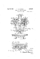
Fig. 1 is a front elevation partially. in section, of'improved sheet glass surfacing apparatus constructed in accordance with the present invention,
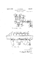
Fig. 2 is a top plan view thereof partially broken away,
Fig. 3 is atransversesection. taken on line 3;3. of Fig.1,
Fig. 4 is a side elevation of the upper portionof the supporting apparatus,
Fig. 5 is a rear view thereof,
Flg. 6 is a section showing a slightly modified-form of the present invention,
Fig. 7 is a detail elevation showing a somewhat modified type of means for guiding the lower end of the surfacing unit, and
Fig. 8- is a top plan view of the modified type of guiding means shown in Fig. 5.
Referring now in detail to the drawings, and especially to Figs. 1 to 5 inclusive, there is disclosed a conventional type of grinding machine designated in its entirety by the nu meral 10, and including a casing 11 in which is journaled a runner spindle 12 driven from a motor 13through the intermediary of suitable reducing gears located in the casing 1.4L Secured to the lower end of the spindle 12by means of a. universal or floating connection 15 is a grinding head 16 carrying the grinding block 17.
ihis machine is shown in connection with the process wherein a series of sheets of glass 18 to be surfaced are supported upon a plurality of tables 19 mounted upon tracks 20, which tables are adapted to carry the glass sheets beneath a plurality of surfacing units to the type hereinabove set forth.
For the purpose of supporting the surfacing unit above the sheets 18, there is provided a carriage designated as a whole by the numeral 21, and including a hollow substantially cone-shaped portion or housing 22 formed at its upper end with an annular shoulder 23.v The surfacing unit 10 is received through the housing 22, and the casing 14 of said unit is provided with an annular flange 24 which rests upon the shoulder 23.
Extending transversely of and adjacent the carriage 21, is a suspension frame including a plate 25, having formed integraltherewith and adjacent its upper edge, a hori zontal supporting beam 26 which rests upon and is secured to a girder 27. Formed integral with the plate 25 at the opposite ends thereof are the forwardly directed extension plates 28 and 29, to the inner adjacent faces of which are secured vertical channel meme bers 30 and 31, the channels 31 of which. are
substantially T-shaped in top plan as shown in Fig. 2.
The upper end of the carriage 21 is provided with oppositely disposed substantially rectangular arms 32 and 33 which are slidably received within the channel members 30 and 31. Also slidably mounted within each of the channel members 30 and 31 is a block 34 substantially T-shaped in top plan to snugly fit within the channel 31. The adjacent faces of the blocks 34 and arms 32 and 33 are provided with pockets 37 and 38 within which are received the opposite ends of compression springs 39 for yieldably sup porting the surfacing unit 10.
In order to raise and lower the surfacing unit 10 and carriage 21, the bottom of each channel member 32 and 33 is closed by means of a wall 40, and inserted upwardly through this wall and also through a plate 41, is an adjusting screw 42 having its upper end received within the block 34. Threaded upon each adjusting screw 42 is a gear 44 in constant mesh with a worm 45 mounted upon a shaft 46 contained within a housing 47.
Each of the shafts 46 extends rearwardly of the surfacing machine as shown in Fig. 4 and is connected by means of a universal joint 78 to a shaft 7 9, which is in turn connected by a universal joint 80 with a shaft 81 having keyed to its outer end a beveled gear 82. The beveled gears 82 are adapted to mesh with similar beveled gears 83 keyed to a horizontal shaft 84 extending transversely of the supporting apparatus. The shaft 84 has secured to one end thereof a beveled gear 85 meshing with a correspondingly bevelled gear 86 mounted at the upper end of the vertically arranged shaft 87, said shaft 87 having keyed to its lower end a bevelled gear 88 meshing with a correspondingly bevelled gear 89 carried by horizontal shaft 90. The shaft 90 has secured thereto a hand wheel 91 and upon rotation of this hand wheel, rotary move ment will be imparted through the shaft and gear arrangement set forth above to the gears 44 whereby to raise or lower the blocks 34 and subsequently the carriage 21 and surfacing unit 10. lVith such a construction, both sides of the supporting apparatus can be simultaneously raised or lowered an equal dis tance whereby to insure proper contact between the grinding blocl: 17 and glass 18. The hand wheel 91 is so positioned that it is readily accessible to the operator of the machine.
Formed integrally with the extensions 28 and 29 are the downwardly converging bracket arms 49 and 50, the lower ends thereof be ing formed integral with a forwardly directed horizontal plate 51 secured to a supporting beam 52. This plate 51 is provided with a recess 53 having notches 54, 55 and 56 within which are slidably received the re duced ends of the arms 57, 58 and 59 extendend of the machine whereby to prevent the same from lateral swinging movement and to also retain the surfacing unit in a perpendicular position. Eyes 60 and 61 are carried by the carriage 21 in order to facilitate the removal thereof together with the unit 10,
while similar eyes 62 and 63 are carried by the surfacing unit 10 in order to facilitate the removal thereof from the carriage 21.
While, for the purpose of illustrating the use and application of the present invention,
there has been disclosed a conventional type of grinding machine, yet it is to be understood that the invention is not restricted for use in connection with grinding machines alone, but may be employed for supporting polishing machines or other types of surfacing machines.
At certain times, the tension of the compression springs 39 will vary somewhat so that one side of the supporting apparatus will be slightly lower or higher than the opposite side thereof with the result that the entire weight of the grinding block 17 will not rest evenly upon the glass being surfaced. In order that this condition may be remedied the channel members 30 and 31 are provided at their upper ends with ears 92 through which are threaded vertical adjusting screws 93, said screws resting upon the upper edges of the extension plates 28 and 29. Passing transversely through the channel members 30 and 31 are suitable bolts 94 which operate within vertical slots 95 formed in the extension plates 28 and 29. Suitable nuts 96 are threaded upon the free ends of the bolts 94. With such a construction, when it is desired to raise or lower one side of the supporting apparatus independently of the other in order to compensate for any difference in the tension of the compression springs 39, it is simply necessary to first loosen the nuts 96 and then, by adjusting the screws 93 in the pro-per direction, raise or lower the channel member at the desired side of the supporting apparatus, after which the nuts 96 should be again tightened to secure the channel member in position. The raising or lowering of the channel member will act to raise or lower the corresponding arm 32 or 33 so that the surfacing unit will be moved to a perpendicular position in order that the entire weight of the grinding block 17, will rest evenly upon the glass being surfaced. The universal couplings 78 and 80 are provided to permit the raising or lowering of the channel members 30 and 31.
In Figs. 6 to 8 inclusive has been shown a somewhat modified form of the present in vention. In this form of the invention, as shown in Fig. 6, it will be noted that the arms 32 and 33- have secured to the under surfaces thereof plungers 64 which are slidably received within cylinders 65 carried by the supporting beam 25. The upper ends of the said plungers are reduced as at 66 and are passed upwardly through the arms 32 and 33, suitable nuts 67 threaded upon the upper free ends of the said reduced portions 66 serving to secure the plungers in position. Encircling the plungers 64 and adjustably carried by the upper ends of the cylinders 65 are packing boxes 68 which prevent dirt from entering the cylinders and also prevent any tendency of the plungers to bind. Also, in this form of the invention the lower ends of the bracket arms l9 and 50 are formed integral with a forwardly directed horizontal plate 69 secured to the supporting beam 52 and provided with a recess 7 O for receiving the lower end of the surfacing unit. The plate 69 is provided with three spaced bearings 71, 72 and 73 within which are slidably received vertical pins 7 4: carried by the outer ends of the arms 75, 76, and 77, which are secured to and extend from the casing 11. Thus, these pins 74 sliding within the bearings 71, 72 and 73 serve to guide the lower end of the surfacing unit during the raising and lowering thereof.
It is to be understood that the form of the invention herewith shown and described is to be taken as the preferred embodiment of the same, and that various changes in the shape, size and arrangement or parts may be resorted to without departing from the spirit of the invention or the scope of the subjoined claims.
Claims:
1. In apparatus for surfacing glass, a substantially vertically arranged surfacing unit including oppositely disposed substantially horizontal supporting arms, a main support, vertical channel members carried by the main support for receiving the arms therein, means within said channel members for yieldably supporting the said arms, and means for securing the channel members to said main support in such a manner that they may be moved vertically with respect thereto.
2. In apparatus for surfacing glass, a substantially vertically arranged surfacing unit including oppositely disposed substantially horizontal supporting arms, a main support, vertical channel members carried by the main support and receiving the supporting arms therein, means for effecting independent vertical adjustment of said channel members with respect to said support, members slidably arranged within the channel members beneath said arms, and spring means interposed between and bearing against said arms and members for yieldably supporting said unit.
3. In apparatus for surfacing glass, a substantially vertically arranged surfacing unit including oppositely disposed substantially horizontal supporting arms, a main support, vertical channel members carried by the main support and receiving the supporting arms therein, means for eflecting independent vertical adjustment of said channel members with respect to said support, blocks slidably mounted within the channel members heneath said arms, compression springs interposed between and bearing against said arms and blocks for yieldably supporting the surfacing unit, and means for adjusting said blocks within said channel members to effect raising and lowering of said unit.
Signed at Toledo, in the county of Lucas I and State of Ohio, this 18th day of October,
ERIK G. STAI-ILE.
Priority Applications (1)
| Application Number | Priority Date | Filing Date | Title |
|---|---|---|---|
| US144667A US1854493A (en) | 1926-10-28 | 1926-10-28 | Sheet glass surfacing apparatus |
Applications Claiming Priority (1)
| Application Number | Priority Date | Filing Date | Title |
|---|---|---|---|
| US144667A US1854493A (en) | 1926-10-28 | 1926-10-28 | Sheet glass surfacing apparatus |
Publications (1)
| Publication Number | Publication Date |
|---|---|
| US1854493A true US1854493A (en) | 1932-04-19 |
Family
ID=22509593
Family Applications (1)
| Application Number | Title | Priority Date | Filing Date |
|---|---|---|---|
| US144667A Expired - Lifetime US1854493A (en) | 1926-10-28 | 1926-10-28 | Sheet glass surfacing apparatus |
Country Status (1)
| Country | Link |
|---|---|
| US (1) | US1854493A (en) |
Cited By (1)
| Publication number | Priority date | Publication date | Assignee | Title |
|---|---|---|---|---|
| US2881569A (en) * | 1955-10-24 | 1959-04-14 | Lempco Products Inc | Grinding machine |
-
1926
- 1926-10-28 US US144667A patent/US1854493A/en not_active Expired - Lifetime
Cited By (1)
| Publication number | Priority date | Publication date | Assignee | Title |
|---|---|---|---|---|
| US2881569A (en) * | 1955-10-24 | 1959-04-14 | Lempco Products Inc | Grinding machine |
Similar Documents
| Publication | Publication Date | Title |
|---|---|---|
| US1958734A (en) | Universal grinder | |
| US1854493A (en) | Sheet glass surfacing apparatus | |
| US2592948A (en) | Roller leveler | |
| US2175296A (en) | Sheet edging machine | |
| US2296934A (en) | Edging machine | |
| US1961487A (en) | Glass grinding machine | |
| US1990002A (en) | Glass grinding apparatus | |
| US2954744A (en) | Movable table propelling and retarding mechanism and mounting for same | |
| US2003905A (en) | Glass grinding machine | |
| US1329551A (en) | Buffing-machine | |
| USRE18533E (en) | of toledo | |
| US2215896A (en) | Balancing wheel for charging machine carriages or the like | |
| US1012651A (en) | Sandpapering-machine. | |
| GB356099A (en) | Machine for finishing edges or strips, sheets and plates of marble, glass and other materials | |
| US2218647A (en) | Corner grinding machine | |
| US1767123A (en) | Glass-surfacing apparatus | |
| US1876457A (en) | iversen | |
| US1856173A (en) | Sheet glass surfacing apparatus | |
| GB727692A (en) | Improvements in or relating to apparatus for simultaneously surfacing both surfaces of a moving ribbon of glass | |
| US1872422A (en) | Sheet glass surfacing apparatus | |
| US1836364A (en) | Sheet glass grinding and polishing apparatus | |
| US2248263A (en) | Edge grinding machine | |
| US2215403A (en) | Locomotive and car wheel grinding machine | |
| US681786A (en) | Machine for rolling configured wire-glass. | |
| US2696131A (en) | Vertical rolling mill |