US1854487A - Railroad track construction - Google Patents
Railroad track construction Download PDFInfo
- Publication number
- US1854487A US1854487A US485137A US48513730A US1854487A US 1854487 A US1854487 A US 1854487A US 485137 A US485137 A US 485137A US 48513730 A US48513730 A US 48513730A US 1854487 A US1854487 A US 1854487A
- Authority
- US
- United States
- Prior art keywords
- rails
- track
- rail
- adjacent
- railroad track
- Prior art date
- Legal status (The legal status is an assumption and is not a legal conclusion. Google has not performed a legal analysis and makes no representation as to the accuracy of the status listed.)
- Expired - Lifetime
Links
- 238000010276 construction Methods 0.000 title description 8
- 241000269350 Anura Species 0.000 description 2
- 230000003028 elevating effect Effects 0.000 description 2
- 241000218645 Cedrus Species 0.000 description 1
- 230000002452 interceptive effect Effects 0.000 description 1
- 230000000284 resting effect Effects 0.000 description 1
Images
Classifications
-
- E—FIXED CONSTRUCTIONS
- E01—CONSTRUCTION OF ROADS, RAILWAYS, OR BRIDGES
- E01B—PERMANENT WAY; PERMANENT-WAY TOOLS; MACHINES FOR MAKING RAILWAYS OF ALL KINDS
- E01B25/00—Tracks for special kinds of railways
- E01B25/28—Rail tracks for guiding vehicles when running on road or similar surface
Definitions
- This invention relates to improvements in railroad track construction, whereby a single truck or carrier may be provided with combined road wheels and track flanges, in such manner that the truck may be operated either on the ordinary railroad track or on highways.
- the object of my invention is to provide an improved track construction whereby the road wheels are automatically and gradually lifted to the same elevation as the top edge of the railroad track, and the adjacent switch and frog members, to permit the road wheels to pass over the intersecting portions of the track rails with a minimum amount of jolting to the truck; and in connection therewith to provide means whereby the flanged wheels will properly move to operative relation with the rails after theyhave crossed the intersecting portions with the flanges of said wheels properly placed thereon, and to permit the steering of the truck to either pair of rails at a switch by means of the customary steering mechanism of the truck and without the necessity of throwing the rail switches.
- My invention consists in the construction, arrangement and combination of the various parts of the device, whereby the objects contemplated are attained, as hereinafter more fully set forth, pointed out in my claims, and illustrated in the accompanying drawings, in which:
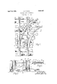
- Figure 1 is a plan view of a portion of my improved track construction.
- Figure 2 is a detail sectional view taken on the line 22 of Figure 1.
- Figure 3 is a detail sectional view taken on the line 3-3 of Figure 1, showing a truck supported thereon of the type designed to be 4.0 used for both road and rail transportation.
- My improvement consists in providing a track 10 having parallel rail members 11, and a second track 12 having rail members 13.
- the track12 intersects the track 11.
- the outer one of the rails 13 intersects the inner rail of the track 11 at the point 1%.
- the usual intersecting frog 15 is provided.
- a frog 16 is provided for the intersection of the outer rails of said track members.
- a switch block 17 is provided at the junction of the intersection of the inner rails of said tracks, said block being provided with a switch 18 of ordinary construction.
- Adjacent to one side of the frog 15 is a platform 19 having at its inner end an inclined portion 20.
- Theplatform 19 is sub stantially the same elevation as the top edge of the rails 11.
- the outer edge of the platform and the inclined portion is provided with an upwardly extending flange 21.
- the 0 opposite side of the frog 15 is provided with a table 22 having an inclined portion 23 adjacent to the inner rail 11, and an inclined portion 24 adjacent to the outer rail 13.
- a table 25 is also provided having an inclined portion 26.
- the inner edges of the members 23 and 24 are provided with upwardly extending flanges 27.
- a table 28 Adjacent to the outer side of the inner rail 13 and adjacent to the block 17 is a table 28 having at each end an inclined portion 29, and at its outer edge an upwardly extending flange 30. Outside of the outer rail 11 and adjacent to the frog 16 is a table 31 having an upwardly extending flange 32 and inclined end portions 33. The top surfaces of all of the tables are substantially level with the top edges of the adjacent rails.
- Said truck comprises a frame 34 having the usual rear axle housing 3.5 and axles 36,
- each of which is provided with a flanged truck may be operated on a highway without the flange engaging the ground surface.
- the truck is operated on a railroad track, then the wheels 37 rest on the rails 11 with the bottom sides of the tires 39 resting below the upper surface of the rails and just above the ties 40.
- a railroad track comprising a pair of parallel rails, and a second track comprising a pair of intersecting rails, the intersecting rails of the track portions including frog and switch members, and an elevating table adjacent to the frogs and switches, each table having a horizontal portion substantialy level with the top edges of said track members, and a downwardly and outwardly inclined end portion, the outside edges of said table and inclined portions being provided with upwardly projecting flanges.
- a railroad track comprising a. pair of parallel rails, and a second track having a pair of intersecting rails, the intersecting rails of the track portions including frog and switch members, and a table adjacent to each of the frogs and switches and adjacent to the adjacent rail portions for engaging a flexible tire of a wheel including a flanged rail wheel, and for gradually elevating the lower surface of the flexible tire to a position level with the top of said rails as the wheel is moved over said frog and switch portions.
- a table adapted to be supported adjacent to a track rail and when so supported having its upper surface substantially level with the top of said rail, one end of said table being inclined downwardly, the outer edge of said table and said inclined portion having an upwardly extending flange.
- a table adapted to be supported adjacent to a track rail and when so supported have its upper surface substantially level with the top of said rail, one end of said table being inclined downwardly, the outer edge of the inclined portion being flared outwardly, the outer edges of said inclined portion and said table having upwardly extending flanges.
- a table adapted to be supported adjacent to a track rail and when so supported having its upper surface substantially level with the top of said rail, one end of said table being inclined downwardly, the outer edge of said table having an upwardly extending flange.
Landscapes
- Engineering & Computer Science (AREA)
- Mechanical Engineering (AREA)
- Architecture (AREA)
- Civil Engineering (AREA)
- Structural Engineering (AREA)
- Railway Tracks (AREA)
Description
April 19, 1932. RQNK 1,854,487
RAILROAD TRACK CONSTRUCTION Filed'Sept. 29, 1950 Patented Apr. 19, 1932 PATENT OFFICE GEORGE T. RONK, F CEDAR RAPIDS, IOWA.
RAILROAD TRACK CONSTRUCTION Application filed September 29, 1930. Serial No. 485,137.
This invention relates to improvements in railroad track construction, whereby a single truck or carrier may be provided with combined road wheels and track flanges, in such manner that the truck may be operated either on the ordinary railroad track or on highways.
The object of my invention is to provide an improved track construction whereby the road wheels are automatically and gradually lifted to the same elevation as the top edge of the railroad track, and the adjacent switch and frog members, to permit the road wheels to pass over the intersecting portions of the track rails with a minimum amount of jolting to the truck; and in connection therewith to provide means whereby the flanged wheels will properly move to operative relation with the rails after theyhave crossed the intersecting portions with the flanges of said wheels properly placed thereon, and to permit the steering of the truck to either pair of rails at a switch by means of the customary steering mechanism of the truck and without the necessity of throwing the rail switches.
My invention consists in the construction, arrangement and combination of the various parts of the device, whereby the objects contemplated are attained, as hereinafter more fully set forth, pointed out in my claims, and illustrated in the accompanying drawings, in which:
Figure 1 is a plan view of a portion of my improved track construction.
\ 55 Figure 2 is a detail sectional view taken on the line 22 of Figure 1.
Figure 3 is a detail sectional view taken on the line 3-3 of Figure 1, showing a truck supported thereon of the type designed to be 4.0 used for both road and rail transportation. My improvement consists in providing a track 10 having parallel rail members 11, and a second track 12 having rail members 13. The track12 intersects the track 11. The
outer one of the rails 13 intersects the inner rail of the track 11 at the point 1%. The usual intersecting frog 15 is provided. A frog 16 is provided for the intersection of the outer rails of said track members. A switch block 17 is provided at the junction of the intersection of the inner rails of said tracks, said block being provided with a switch 18 of ordinary construction.
Adjacent to one side of the frog 15 is a platform 19 having at its inner end an inclined portion 20. Theplatform 19 is sub stantially the same elevation as the top edge of the rails 11. The outer edge of the platform and the inclined portion is provided with an upwardly extending flange 21. The 0 opposite side of the frog 15 is provided with a table 22 having an inclined portion 23 adjacent to the inner rail 11, and an inclined portion 24 adjacent to the outer rail 13. A table 25 is also provided having an inclined portion 26. The inner edges of the members 23 and 24 are provided with upwardly extending flanges 27.
Adjacent to the outer side of the inner rail 13 and adjacent to the block 17 is a table 28 having at each end an inclined portion 29, and at its outer edge an upwardly extending flange 30. Outside of the outer rail 11 and adjacent to the frog 16 is a table 31 having an upwardly extending flange 32 and inclined end portions 33. The top surfaces of all of the tables are substantially level with the top edges of the adjacent rails.
Thus it will be seen that I have provided means whereby a truck such as illustrated in Figure 3, and which is adapted to be-operated either on a highway or on rails, may be operated on the ordinary rail track after my improved table devices above described have been applied thereto. 7
Said truck comprises a frame 34 having the usual rear axle housing 3.5 and axles 36,
each of which is provided with a flanged truck may be operated on a highway without the flange engaging the ground surface.
l/Vhen the truck is operated on a railroad track, then the wheels 37 rest on the rails 11 with the bottom sides of the tires 39 resting below the upper surface of the rails and just above the ties 40.
On account of the lower sides of the tires 39 being supported a considerable distance below the upper edges of the rails, it will be seen that if the truck is moved over the rails 11 to position over the switch 17, and the frog'16, then the tires would abruptly engage the intersecting rails 12 and 13, cansing the truck to be thrown upwardly and possibly the flanges thrown out of engage ment with the rail as they are lowered into position after crossing the tracks.
Furthermore, it will be seen that the sides of the lower portions of the flexible tires would engage the diverging rail or switch members, which would have a tendency to pull the trucks in the path of the intersecting tracks. This will take place at the same time the flanges are being lifted from the rails. By providing my improved tables, I have provided means whereby the wheels will be gradually elevated as the flexible tires engage the inclined portions of the tables, permitting the wheels to pass over the frog and switch portions, and then to be gradually lowered into position.
Thus it will be seen that I have provided improved means whereby the ordinary railroad track may be easily and quickly converted into a track which is adapted to operate trucks of the type above described without interfering with the operation of the railroad trains, as the application of my improved tables in no way interferes with the operation of the trains. Neither is it necessary to provide any special switching arrangement.
I claim as my invention:
1. In combination, a railroad track comprising a pair of parallel rails, and a second track comprising a pair of intersecting rails, the intersecting rails of the track portions including frog and switch members, and an elevating table adjacent to the frogs and switches, each table having a horizontal portion substantialy level with the top edges of said track members, and a downwardly and outwardly inclined end portion, the outside edges of said table and inclined portions being provided with upwardly projecting flanges.
2. In combination, a railroad track comprising a. pair of parallel rails, and a second track having a pair of intersecting rails, the intersecting rails of the track portions including frog and switch members, and a table adjacent to each of the frogs and switches and adjacent to the adjacent rail portions for engaging a flexible tire of a wheel including a flanged rail wheel, and for gradually elevating the lower surface of the flexible tire to a position level with the top of said rails as the wheel is moved over said frog and switch portions.
3. In a railroad track, the combination of intersecting rails, a table supported in one of the angular spaces between said intersecting rails, the top of said table being substantially even with the top surface of said rails and having diverging end portions each terminating in a downwardly inclined portion, the outer edges of said diverging portions being provided with upwardly projecting flanges.
4. In adevice of the class described, a table adapted to be supported adjacent to a track rail and when so supported having its upper surface substantially level with the top of said rail, one end of said table being inclined downwardly, the outer edge of said table and said inclined portion having an upwardly extending flange.
5. In a device of the class described, a table adapted to be supported adjacent to a track rail and when so supported have its upper surface substantially level with the top of said rail, one end of said table being inclined downwardly, the outer edge of the inclined portion being flared outwardly, the outer edges of said inclined portion and said table having upwardly extending flanges.
6. In a device of the class described, a table adapted to be supported adjacent to a track rail and when so supported having its upper surface substantially level with the top of said rail, one end of said table being inclined downwardly, the outer edge of said table having an upwardly extending flange.
Des Moines, Iowa, August 25, 1930.
GEORGE T. RONK.
Priority Applications (1)
| Application Number | Priority Date | Filing Date | Title |
|---|---|---|---|
| US485137A US1854487A (en) | 1930-09-29 | 1930-09-29 | Railroad track construction |
Applications Claiming Priority (1)
| Application Number | Priority Date | Filing Date | Title |
|---|---|---|---|
| US485137A US1854487A (en) | 1930-09-29 | 1930-09-29 | Railroad track construction |
Publications (1)
| Publication Number | Publication Date |
|---|---|
| US1854487A true US1854487A (en) | 1932-04-19 |
Family
ID=23927035
Family Applications (1)
| Application Number | Title | Priority Date | Filing Date |
|---|---|---|---|
| US485137A Expired - Lifetime US1854487A (en) | 1930-09-29 | 1930-09-29 | Railroad track construction |
Country Status (1)
| Country | Link |
|---|---|
| US (1) | US1854487A (en) |
Cited By (4)
| Publication number | Priority date | Publication date | Assignee | Title |
|---|---|---|---|---|
| US2541514A (en) * | 1944-09-29 | 1951-02-13 | Bassick Co | Industrial truck caster wheel |
| US3119349A (en) * | 1959-05-13 | 1964-01-28 | Pneuways Dev Company Private L | Track-mounted transport means or systems |
| DE3244231A1 (en) * | 1981-11-30 | 1983-06-09 | Elevator GmbH, 6340 Baar | RAIL SYSTEM FOR ROLLING PALLETS OR ROLLING CONTAINERS |
| US11230813B1 (en) * | 2020-10-16 | 2022-01-25 | Thomas Holtzman Williams | Automated road-rail transportation system with side stabilization |
-
1930
- 1930-09-29 US US485137A patent/US1854487A/en not_active Expired - Lifetime
Cited By (4)
| Publication number | Priority date | Publication date | Assignee | Title |
|---|---|---|---|---|
| US2541514A (en) * | 1944-09-29 | 1951-02-13 | Bassick Co | Industrial truck caster wheel |
| US3119349A (en) * | 1959-05-13 | 1964-01-28 | Pneuways Dev Company Private L | Track-mounted transport means or systems |
| DE3244231A1 (en) * | 1981-11-30 | 1983-06-09 | Elevator GmbH, 6340 Baar | RAIL SYSTEM FOR ROLLING PALLETS OR ROLLING CONTAINERS |
| US11230813B1 (en) * | 2020-10-16 | 2022-01-25 | Thomas Holtzman Williams | Automated road-rail transportation system with side stabilization |
Similar Documents
| Publication | Publication Date | Title |
|---|---|---|
| US1854487A (en) | Railroad track construction | |
| US2150348A (en) | Railway | |
| US27978A (en) | Samuel m | |
| US1355466A (en) | Tramcar | |
| US2043645A (en) | Switch brace and rerailer | |
| US945140A (en) | Derailment safety device for railway-trucks. | |
| US749609A (en) | Railroad | |
| US591597A (en) | Railroad | |
| US1410059A (en) | Rerailer | |
| US889369A (en) | Normal-surface transfer-table. | |
| US1404479A (en) | Turntable for motor vehicles | |
| US1438341A (en) | Combination locomotive and coach hoist | |
| US1757403A (en) | Car-replacing rail | |
| US1323975A (en) | Railroad-crossing evener | |
| US40694A (en) | Improvement in railroad-switches | |
| US1536122A (en) | Pleasure-railway structure | |
| US839633A (en) | Railway. | |
| US326212A (en) | Construction and operation op permanent railroads | |
| US1246921A (en) | Transportation system. | |
| US2088835A (en) | Railway car construction | |
| GB454878A (en) | Improvements in or relating to road vehicles for the combined road and rail transport of material | |
| US547823A (en) | Triple-track safety-railway | |
| US388073A (en) | Track device for handling cars | |
| US574807A (en) | lancaster | |
| US1081717A (en) | Device for replacing derailed cars. |