US1854481A - Machine for forming channels in pads - Google Patents
Machine for forming channels in pads Download PDFInfo
- Publication number
- US1854481A US1854481A US350998A US35099829A US1854481A US 1854481 A US1854481 A US 1854481A US 350998 A US350998 A US 350998A US 35099829 A US35099829 A US 35099829A US 1854481 A US1854481 A US 1854481A
- Authority
- US
- United States
- Prior art keywords
- pad
- cutters
- shaft
- pads
- cuts
- Prior art date
- Legal status (The legal status is an assumption and is not a legal conclusion. Google has not performed a legal analysis and makes no representation as to the accuracy of the status listed.)
- Expired - Lifetime
Links
Images
Classifications
-
- B—PERFORMING OPERATIONS; TRANSPORTING
- B68—SADDLERY; UPHOLSTERY
- B68G—METHODS, EQUIPMENT, OR MACHINES FOR USE IN UPHOLSTERING; UPHOLSTERY NOT OTHERWISE PROVIDED FOR
- B68G7/00—Making upholstery
-
- Y—GENERAL TAGGING OF NEW TECHNOLOGICAL DEVELOPMENTS; GENERAL TAGGING OF CROSS-SECTIONAL TECHNOLOGIES SPANNING OVER SEVERAL SECTIONS OF THE IPC; TECHNICAL SUBJECTS COVERED BY FORMER USPC CROSS-REFERENCE ART COLLECTIONS [XRACs] AND DIGESTS
- Y10—TECHNICAL SUBJECTS COVERED BY FORMER USPC
- Y10T—TECHNICAL SUBJECTS COVERED BY FORMER US CLASSIFICATION
- Y10T83/00—Cutting
- Y10T83/02—Other than completely through work thickness
- Y10T83/0304—Grooving
-
- Y—GENERAL TAGGING OF NEW TECHNOLOGICAL DEVELOPMENTS; GENERAL TAGGING OF CROSS-SECTIONAL TECHNOLOGIES SPANNING OVER SEVERAL SECTIONS OF THE IPC; TECHNICAL SUBJECTS COVERED BY FORMER USPC CROSS-REFERENCE ART COLLECTIONS [XRACs] AND DIGESTS
- Y10—TECHNICAL SUBJECTS COVERED BY FORMER USPC
- Y10T—TECHNICAL SUBJECTS COVERED BY FORMER US CLASSIFICATION
- Y10T83/00—Cutting
- Y10T83/202—With product handling means
- Y10T83/2066—By fluid current
- Y10T83/207—By suction means
-
- Y—GENERAL TAGGING OF NEW TECHNOLOGICAL DEVELOPMENTS; GENERAL TAGGING OF CROSS-SECTIONAL TECHNOLOGIES SPANNING OVER SEVERAL SECTIONS OF THE IPC; TECHNICAL SUBJECTS COVERED BY FORMER USPC CROSS-REFERENCE ART COLLECTIONS [XRACs] AND DIGESTS
- Y10—TECHNICAL SUBJECTS COVERED BY FORMER USPC
- Y10T—TECHNICAL SUBJECTS COVERED BY FORMER US CLASSIFICATION
- Y10T83/00—Cutting
- Y10T83/647—With means to convey work relative to tool station
- Y10T83/6476—Including means to move work from one tool station to another
- Y10T83/6489—Slitter station
-
- Y—GENERAL TAGGING OF NEW TECHNOLOGICAL DEVELOPMENTS; GENERAL TAGGING OF CROSS-SECTIONAL TECHNOLOGIES SPANNING OVER SEVERAL SECTIONS OF THE IPC; TECHNICAL SUBJECTS COVERED BY FORMER USPC CROSS-REFERENCE ART COLLECTIONS [XRACs] AND DIGESTS
- Y10—TECHNICAL SUBJECTS COVERED BY FORMER USPC
- Y10T—TECHNICAL SUBJECTS COVERED BY FORMER US CLASSIFICATION
- Y10T83/00—Cutting
- Y10T83/647—With means to convey work relative to tool station
- Y10T83/6584—Cut made parallel to direction of and during work movement
- Y10T83/6606—Tool between laterally spaced work-conveying means
Definitions
- ED077157 Gar/"aw Wflfudd Aprifi 19, 1932.
- G. w. MUDD MACHINE FOR FORMING CHANNELS IN PADS Original Filed March 29, 1929 3 Sheets-Sheet Ramp Gav/w W ilfudd Patented Apr. 19, 1932 GARRETT W. MUDID, OF CHICAGO, ILLINOIS, ASSIGNOR, BY MESNE ASSIGNMENTS, TO CHICAGO CURLED- HAIR COMPANY, OF CHICAGO, ILLINOIS, A CORPORATION OF ILLINOIS MACHINE FOR FORMING CHANNELS IN PADS Application filed March 29, 1929, Serial No. 350,998. Renewed September 12, 1931.
- This invention relates to improvements in machines for cutting pads constructed of hair, moss or other suitable fibrous material which are used for upholstering and the like, and one of the objects of the invention is to provide improved means for cutting the body of the pad partially therethrough and for then removing the material from the cut portion to form a channel or recess extending across the pad and opening through the face thereof, all while the pad is passing through the machine.
- a further object is to provide improved means for removing the hair, fiber, or other material forming the body of the pad, and improved means for carrying away such removed material.
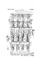
- Figure 1 is a top plan view, partly broken away and with parts omitted of a machine of this character constructed in accordance with the principles of this invention.
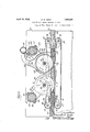
- Figure 2 is a vertical, longitudinal sectional view as taken on line 2-2, Figure 1.
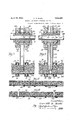
- Figure 3 is a detail sectional view taken on line 3-3, Figure 2.
- Figure 4 is a detail sectional view taken on line 4-4, Figure 2.
- Figure 5 is a detail sectional view of a pad showing the same secured to a backing and bofore the pad is treated by this process.
- Figure 6 is a view similar to Figure 5, showing the pad with channels formed therein.
- the numeral 10 designates the sides of a supporting frame which may be of any desired size and configuration and secured thereacross and in suitable positions are coo-perating pairs of shafts 11-12, the shafts of each pair being superposed.
- Endless conveyor elements 13 are arranged to pass over co-operat-ing sprocket wheels 1415 on the upper shafts 11 and 12 and similar endless conveyors 16 are arranged to co-operate with the conveyors 13 and pass over sprockets 1718 respectively on the lowermost shafts 1112 of the pairs.
- the shafts may be driven in any suitable or desired manner preferably from a pulley 19 secured to one of the shafts and which receives its motion from any suitable source. If desired a gear wheel 20 may be secured to the shaft which is driven by the pulley 19 and motion may be imparted from this gear wheel 20 to one of the shafts of the other endless conveyor.
- the pad 21 is advanced between the proximate runs of the conveyors 1316 and these runs are suitably spaced according to the thickness of the pad to be operated upon.
- the pad preferably embodies a backing 22 constructed of any suitable material, such as burlap or the like and the material is secured to the backing by interlacing the same in any well known and suitable manner so as to pull portions of the pad through the backing 22.
- a shaft or supporting member 24 Secured between the sides of the support ing frame is a shaft or supporting member 24 and mounted upon this shaft are a plurality of pairs of arms 25 being secured to the shaft in any suitable manner preferably by means of semi-circular members 2627 which encompass the shaft and these members are secured together by suitable fastening devices 28 so as to clamp the shaft 24 and thereby secure the arms to the shaft, suitable key devices 29 being also provided, if desired.
- the shaft 24 is adjustably held in position preferably by means of fastening bolts which pass through the side members of the iii) main supporting structure and into the shaft 24 so that by loosening the fastening devices the shaft 24 may be axially rotated to raise or lower the arms 25 and to secure them in the desired position.
- any number of these pairs of arms 25 may be provided according to the width of the pad being operated upon and the number of channels which it is desired to form in the p
- a shaft 31 passes through and is journaled in each of the arms 25 and mounted upon the shaft 31 are any desired number of spaced rotary cutters or knives 32 which are maintained in the desired spaced relation by means of suitable spacers 33.
- the cutters 32 are preferably mounted upon a sleeve 34 which encompasses the shaft 31 and a key and slot connection 3536 may be provided between the sleeve and the shaft 31.
- Ball bearings 37 may be provided for clamping the cutters to the sleeve 34 and a suitable clamping collar 38 is threaded upon the sleeve 34 and co-operates with a flange 39 on the collar 34 for securing the cutters in position.
- any other suitable means may be provided for mounting the cutters upon the shaft 31.
- the shaft 31 is adapted to be moved longil tudinally through the arms 25 so that it may be disconnected from an operating motor 40 or if desired an adjustable coupling 41 may be provided to form a connection between the motor shaft and the shaft 31.
- the cutters 32 may be positioned to cut for any desired distance through the body of the pad 21, but in the present form of the invention the cutters are shown as cutting to a point in close -1 proximity to the backing 22. These cutter may be suitably spaced according to the width of the groove or channel which it is desired to produce.
- the conveyors 13 and 16 are preferably arranged in pairs as shown more clearly in Figure 3 and are adapted to operate respectively in guides 42-43 so as to hold them in close proximity to the pad 21 for advancing the pad and also for holding the pad during the cutting operation.
- the cutters will operate to cut spaced parallel lines through the body of the pad and after the pad has been thus cut the material between the cuts is removed so as to form a channel 44 opening through the face of the pad, the backing 22 of the pad forming the bottom of the channel.
- One of these channels will be cut by each pair of cutters 32.
- a simple and eflicient means embodies a rotary drum like picker 45 provided with picking teeth 46 about its periphery, one picker being provided for each pair of cutters 32.
- These pickers 45 may be operated in any desired or suitable manner either by gearing the same to other parts of the mechanism or by means of a separate motor 47 which is connected by means of a suitable coupling 48 with a shaft 49.
- This shaft 49 passes through each of the pickers 45 and the picking devices are secured to the shaft in any suitable manner such as by means of a sleeve 50 having a flange 51 at one end thereof and a threaded portion at the other end to receive a nut or collar 52.
- Ball bearings 53 being respectively provided between the flange 51 and the collar or nut 52 on each side of the hub 54 of the picker element for clamping the latter, and the collar 50 may be secured by pin and groove connections 5556 with the shaft 49.
- the shaft 49 is also journaled in spaced arms 57, one arranged on each side of each of the pickers 45 and these arms 57 are provided with semi-circular port-ions 5859 which encompass a sh aft or support 60 secured in position preferably in a manner somewhat similar to the manner in which the shaft 24 is secured so that by rotating the shaft 60 the arms 57 which are clamped to the shaft 60 by means of suitable fastening devices 61 and keyed thereto by means of a key 62, may be raised or lowered to position the pickers 45 to remove the cut material to a predetermined depth, that is so that a channel of any desired depth may be formed.
- the picking element 45 will operate upon the out material and will pick it out or remove it from the pad to form the channels 44 which open through the face of the pad.
- a suitable guard 63 may be provided for the pickers and this guard consitutes a housing in which the pickers operate.
- a conduit. 64 has communication by means of a pipe 65 with the housing 63 and a suction may be created in the conduit 64 so that the material which is removed by the pickers will be delivered to the housing 63 and conveyed through the conduit 64 to the pipe 65 to be conveyed away from the machine.
- the pad after the pad has been first placed in the machine it will be advanced continuously and during the advancing movement it will be cut to a predetermined depth by the cutters As the pad advances further the picking devices 45 will operate upon the material between the cuts formed by the cutters 32 and this material will be picked or removed from the pad and delivered into the housing 63 to be conveyed away. The removal of the material between the two co-operating cuts will form a channel opening through the top of the pad, the backing of the pad forming the bottom of the channel.
- the material need not be cut entirely therethrough to the pad and a small portion of the material may be allowed to remain to form the bottom of the channel.
- this device will be a continuously operating device and both the cutters and pickers may be adjusted to operate to any desired depth with respect to the thickness of the pad and when the channels are formed in the pad, the portions of the pad which remain after the formation of the channels will not be entirely severed.
- Means for forming channels in felt pads and the like comprising means fer advancing said pad, means for effecting spaced parallel cuts across the pad as it is advanced, picking means for picking out the material from between said cuts to provide a channel in the pad, and means for actuating the picking means.
- Means for forming channels in felt pads and the like comprising means for advancing said pad, means for effecting spaced parallel cuts across the pad as it is advanced, picking means for picking out the material from be tween said cuts to provide a channel in the pad, means for actuating the picking means, and pneumatic means for conveying away the material as it is thus removed from between said cuts.
- Means for forming channels in felt pads and the like comprising means for effecting spaced parallel cuts partially through the pad, means for effecting an advancing movement of said cutting means and the pad, one with relation to the other, picking means for picking out the material of the pad adjacent to the cut portion, and means for actuating the picking means.
- Means for forming channels in felt pads and the like comprising means for effecting spaced parallel cuts partially through the pad, means for effecting an advancing movement of the said cutting means and the pad one with relation tothe other, picking means for picking out the material of the pad adjacent the said out portion, means for actuating the picking means, and means for cenveying away the material as it thus removed.
- Means for forming channels in felt pads and the like having a backing comprising means for advancing the pad, means for forming spaced cuts across and through the pad to the said backing, a picker operating to pick out and remove the material from between said cuts to form an open channel across the pad, and means for actuating the picker, the said backing forming the bottom of the channel.
- Means for forming channels in fibrous pads embodying means for advancing the pad, laterally spaced cutters, means for operating the cutters to cause them to cut partially through the pad, a rotary picker for removing the portion of the pad between said cuts, and means for actuating the said picker.
- Means for forming channels in fibrous pads embodying means for advancing the pad, laterally spaced cutters, means for operating the cutters to cause them to cut p ar tiallv through the pad, a rotary picker for picking out the portion of the pad between said cuts, means for rotating said picker, and means whereby said cutters may be laterally adjusted one with respect to the other.
- Means for forming channels in fibrous pads embodying means for advancing the pad, laterally spaced cutters operating to form cuts extending partially through said pad, a picker for removing the material beioo tween said cuts to form a channel opening through the face of the pad, a guard forming a housing in which the picker operates, and a conveyor for conveying away from the housing the material thus removed.
- Means for forming channels in fibrous pads embodying means for advancing the pad, laterally spaced cutters operating to form cuts extending partially through said pad, a picker for removing the material between said cuts to form a channel opening through the face of the pad, a guard forming a housing in which the picker operates, and a pneumatic conveyor having communication with said housing for conveying away from the said picker the material as it is removed from said pad.
- Means for forming channels in fibrous pads embodying means for advancing the pad, laterally spaced rotary cutters for cutting partially through the pad, means for actuating the cutters, a rotary picker drum operating to remove the material of the pad which. is between said cuts to form channels opening through the face of the pad, and means for conveying away the said material directly it is removed by the picker drum.
- Means for forming channels in fibrous pads embodying laterally spaced cutters for cutting partially through the pad, means for advancing the pad with respect to the cutters and for holding the pad while it is being advanced and thus cut, a rotary clrum picker operating on the material between said cuts to remove it from the pad as the pad is advancecl to form channels opening through the face of the pacl and means for receiving the material from the picker and for conveying it away.
Landscapes
- Engineering & Computer Science (AREA)
- Manufacturing & Machinery (AREA)
- Mechanical Engineering (AREA)
- Treatment Of Fiber Materials (AREA)
Description
April 19, 1932. w, MUDD 1,854,481
MACHINE FOR FORMING CHANNELS IN PADS Original Filed March 29, 1929 5 Sheets-Sheet 1 April 19, 1932. G. w. MUDD MACHINE FOR FORMING CHANNELS IN PADS Original Filed March 29, 1929 I5 Sheets-Sheet 2 B @H om a,
N tiuliulllillllllni-lnl T L T N 6 L m m 1.. l
ED077157: Gar/"aw Wflfudd Aprifi 19, 1932. G. w. MUDD MACHINE FOR FORMING CHANNELS IN PADS Original Filed March 29, 1929 3 Sheets-Sheet Ramp Gav/w W ilfudd Patented Apr. 19, 1932 GARRETT W. MUDID, OF CHICAGO, ILLINOIS, ASSIGNOR, BY MESNE ASSIGNMENTS, TO CHICAGO CURLED- HAIR COMPANY, OF CHICAGO, ILLINOIS, A CORPORATION OF ILLINOIS MACHINE FOR FORMING CHANNELS IN PADS Application filed March 29, 1929, Serial No. 350,998. Renewed September 12, 1931.
This invention relates to improvements in machines for cutting pads constructed of hair, moss or other suitable fibrous material which are used for upholstering and the like, and one of the objects of the invention is to provide improved means for cutting the body of the pad partially therethrough and for then removing the material from the cut portion to form a channel or recess extending across the pad and opening through the face thereof, all while the pad is passing through the machine.
A further object is to provide improved means for removing the hair, fiber, or other material forming the body of the pad, and improved means for carrying away such removed material. I
To the attainment of these ends and the accomplishment of other new and useful objects as will appear,the invention consists in the features of novelty in substantially the construction, combination and arrangement of the several parts hereinafter more fully described and claimed and shown in the accompanying drawings illustrating this invention,
and in which Figure 1 is a top plan view, partly broken away and with parts omitted of a machine of this character constructed in accordance with the principles of this invention.
Figure 2 is a vertical, longitudinal sectional view as taken on line 2-2, Figure 1.
Figure 3 is a detail sectional view taken on line 3-3, Figure 2.
Figure 4 is a detail sectional view taken on line 4-4, Figure 2.
Figure 5 is a detail sectional view of a pad showing the same secured to a backing and bofore the pad is treated by this process.
Figure 6 is a view similar to Figure 5, showing the pad with channels formed therein.
Referring more particularly to the drawings the numeral 10 designates the sides of a supporting frame which may be of any desired size and configuration and secured thereacross and in suitable positions are coo-perating pairs of shafts 11-12, the shafts of each pair being superposed. Endless conveyor elements 13 are arranged to pass over co-operat-ing sprocket wheels 1415 on the upper shafts 11 and 12 and similar endless conveyors 16 are arranged to co-operate with the conveyors 13 and pass over sprockets 1718 respectively on the lowermost shafts 1112 of the pairs.
The shafts may be driven in any suitable or desired manner preferably from a pulley 19 secured to one of the shafts and which receives its motion from any suitable source. If desired a gear wheel 20 may be secured to the shaft which is driven by the pulley 19 and motion may be imparted from this gear wheel 20 to one of the shafts of the other endless conveyor.
The pad 21 is advanced between the proximate runs of the conveyors 1316 and these runs are suitably spaced according to the thickness of the pad to be operated upon.
The pad preferably embodies a backing 22 constructed of any suitable material, such as burlap or the like and the material is secured to the backing by interlacing the same in any well known and suitable manner so as to pull portions of the pad through the backing 22.
Secured between the sides of the support ing frame is a shaft or supporting member 24 and mounted upon this shaft are a plurality of pairs of arms 25 being secured to the shaft in any suitable manner preferably by means of semi-circular members 2627 which encompass the shaft and these members are secured together by suitable fastening devices 28 so as to clamp the shaft 24 and thereby secure the arms to the shaft, suitable key devices 29 being also provided, if desired.
The shaft 24 is adjustably held in position preferably by means of fastening bolts which pass through the side members of the iii) main supporting structure and into the shaft 24 so that by loosening the fastening devices the shaft 24 may be axially rotated to raise or lower the arms 25 and to secure them in the desired position.
Any number of these pairs of arms 25 may be provided according to the width of the pad being operated upon and the number of channels which it is desired to form in the p A shaft 31 passes through and is journaled in each of the arms 25 and mounted upon the shaft 31 are any desired number of spaced rotary cutters or knives 32 which are maintained in the desired spaced relation by means of suitable spacers 33. The cutters 32 are preferably mounted upon a sleeve 34 which encompasses the shaft 31 and a key and slot connection 3536 may be provided between the sleeve and the shaft 31.
The shaft 31 is adapted to be moved longil tudinally through the arms 25 so that it may be disconnected from an operating motor 40 or if desired an adjustable coupling 41 may be provided to form a connection between the motor shaft and the shaft 31.
By adjusting the shaft 24 the cutters 32 may be positioned to cut for any desired distance through the body of the pad 21, but in the present form of the invention the cutters are shown as cutting to a point in close -1 proximity to the backing 22. These cutter may be suitably spaced according to the width of the groove or channel which it is desired to produce.
The conveyors 13 and 16 are preferably arranged in pairs as shown more clearly in Figure 3 and are adapted to operate respectively in guides 42-43 so as to hold them in close proximity to the pad 21 for advancing the pad and also for holding the pad during the cutting operation.
After the arms 25 have been set to position the periphery of the cutters 32 at any desired point with respect to the backing of the pad 22 and the pad is advanced by means of the conveyors 1316, the cutters will operate to cut spaced parallel lines through the body of the pad and after the pad has been thus cut the material between the cuts is removed so as to form a channel 44 opening through the face of the pad, the backing 22 of the pad forming the bottom of the channel. One of these channels will be cut by each pair of cutters 32.
Any suitable means may be provided for removing the cut material, but a simple and eflicient means embodies a rotary drum like picker 45 provided with picking teeth 46 about its periphery, one picker being provided for each pair of cutters 32. These pickers 45 may be operated in any desired or suitable manner either by gearing the same to other parts of the mechanism or by means of a separate motor 47 which is connected by means of a suitable coupling 48 with a shaft 49. This shaft 49 passes through each of the pickers 45 and the picking devices are secured to the shaft in any suitable manner such as by means of a sleeve 50 having a flange 51 at one end thereof and a threaded portion at the other end to receive a nut or collar 52. Ball bearings 53 being respectively provided between the flange 51 and the collar or nut 52 on each side of the hub 54 of the picker element for clamping the latter, and the collar 50 may be secured by pin and groove connections 5556 with the shaft 49.
The shaft 49 is also journaled in spaced arms 57, one arranged on each side of each of the pickers 45 and these arms 57 are provided with semi-circular port-ions 5859 which encompass a sh aft or support 60 secured in position preferably in a manner somewhat similar to the manner in which the shaft 24 is secured so that by rotating the shaft 60 the arms 57 which are clamped to the shaft 60 by means of suitable fastening devices 61 and keyed thereto by means of a key 62, may be raised or lowered to position the pickers 45 to remove the cut material to a predetermined depth, that is so that a channel of any desired depth may be formed.
Thus is will be seen that after the pad has been operated upon by the cutters 32 and during its advancing movement the picking element 45 will operate upon the out material and will pick it out or remove it from the pad to form the channels 44 which open through the face of the pad.
A suitable guard 63 may be provided for the pickers and this guard consitutes a housing in which the pickers operate. A conduit. 64 has communication by means of a pipe 65 with the housing 63 and a suction may be created in the conduit 64 so that the material which is removed by the pickers will be delivered to the housing 63 and conveyed through the conduit 64 to the pipe 65 to be conveyed away from the machine.
Thus it will be seen that after the pad has been first placed in the machine it will be advanced continuously and during the advancing movement it will be cut to a predetermined depth by the cutters As the pad advances further the picking devices 45 will operate upon the material between the cuts formed by the cutters 32 and this material will be picked or removed from the pad and delivered into the housing 63 to be conveyed away. The removal of the material between the two co-operating cuts will form a channel opening through the top of the pad, the backing of the pad forming the bottom of the channel.
If, however, it is desired, the material need not be cut entirely therethrough to the pad and a small portion of the material may be allowed to remain to form the bottom of the channel.
t will also be manifest that this device will be a continuously operating device and both the cutters and pickers may be adjusted to operate to any desired depth with respect to the thickness of the pad and when the channels are formed in the pad, the portions of the pad which remain after the formation of the channels will not be entirely severed.
While the preferred form of the invention has been herein shown and described, it is to be understood that various changes may be made in the details of construction and in the combination and arrangement of the several parts, within the scope of the claims, without departing from the spirit of this invention.
Wh at is claimed as new is 1. Means for forming channels in felt pads and the like comprising means fer advancing said pad, means for effecting spaced parallel cuts across the pad as it is advanced, picking means for picking out the material from between said cuts to provide a channel in the pad, and means for actuating the picking means.
2. Means for forming channels in felt pads and the like comprising means for advancing said pad, means for effecting spaced parallel cuts across the pad as it is advanced, picking means for picking out the material from be tween said cuts to provide a channel in the pad, means for actuating the picking means, and pneumatic means for conveying away the material as it is thus removed from between said cuts.
3. Means for forming channels in felt pads and the like comprising means for effecting spaced parallel cuts partially through the pad, means for effecting an advancing movement of said cutting means and the pad, one with relation to the other, picking means for picking out the material of the pad adjacent to the cut portion, and means for actuating the picking means.
4. Means for forming channels in felt pads and the like comprising means for effecting spaced parallel cuts partially through the pad, means for effecting an advancing movement of the said cutting means and the pad one with relation tothe other, picking means for picking out the material of the pad adjacent the said out portion, means for actuating the picking means, and means for cenveying away the material as it thus removed.
5. Means for forming channels in felt pads and the like having a backing, comprising means for advancing the pad, means for forming spaced cuts across and through the pad to the said backing, a picker operating to pick out and remove the material from between said cuts to form an open channel across the pad, and means for actuating the picker, the said backing forming the bottom of the channel.
6. Means for forming channels in felt pads I n in the rear of the cutter in the line of travel of the pad for removing the portion of the pad between said cuts, and means for actuating the picker.
7 Means for forming channels in fibrous pads embodying means for advancing the pad, laterally spaced cutters, means for operating the cutters to cause them to cut partially through the pad, a rotary picker for removing the portion of the pad between said cuts, and means for actuating the said picker.
8. Means for forming channels in fibrous pads embodying means for advancing the pad, laterally spaced cutters, means for operating the cutters to cause them to cut p ar tiallv through the pad, a rotary picker for picking out the portion of the pad between said cuts, means for rotating said picker, and means whereby said cutters may be laterally adjusted one with respect to the other.
9. Means for forming channels in fibrous pads embodying means for advancing the pad, laterally spaced cutters operating to form cuts extending partially through said pad, a picker for removing the material beioo tween said cuts to form a channel opening through the face of the pad, a guard forming a housing in which the picker operates, and a conveyor for conveying away from the housing the material thus removed.
10. Means for forming channels in fibrous pads embodying means for advancing the pad, laterally spaced cutters operating to form cuts extending partially through said pad, a picker for removing the material between said cuts to form a channel opening through the face of the pad, a guard forming a housing in which the picker operates, and a pneumatic conveyor having communication with said housing for conveying away from the said picker the material as it is removed from said pad.
11. Means for forming channels in fibrous pads embodying means for advancing the pad, laterally spaced rotary cutters for cutting partially through the pad, means for actuating the cutters, a rotary picker drum operating to remove the material of the pad which. is between said cuts to form channels opening through the face of the pad, and means for conveying away the said material directly it is removed by the picker drum.
12. Means for forming channels in fibrous pads embodying laterally spaced cutters for cutting partially through the pad, means for advancing the pad with respect to the cutters and for holding the pad while it is being advanced and thus cut, a rotary clrum picker operating on the material between said cuts to remove it from the pad as the pad is advancecl to form channels opening through the face of the pacl and means for receiving the material from the picker and for conveying it away.
In testimony whereof I have signed my name to this specification, on this 18th clay of March, A. D. 1929.
GARRETT W. MUDD.
Priority Applications (1)
| Application Number | Priority Date | Filing Date | Title |
|---|---|---|---|
| US350998A US1854481A (en) | 1929-03-29 | 1929-03-29 | Machine for forming channels in pads |
Applications Claiming Priority (1)
| Application Number | Priority Date | Filing Date | Title |
|---|---|---|---|
| US350998A US1854481A (en) | 1929-03-29 | 1929-03-29 | Machine for forming channels in pads |
Publications (1)
| Publication Number | Publication Date |
|---|---|
| US1854481A true US1854481A (en) | 1932-04-19 |
Family
ID=23379154
Family Applications (1)
| Application Number | Title | Priority Date | Filing Date |
|---|---|---|---|
| US350998A Expired - Lifetime US1854481A (en) | 1929-03-29 | 1929-03-29 | Machine for forming channels in pads |
Country Status (1)
| Country | Link |
|---|---|
| US (1) | US1854481A (en) |
Cited By (13)
| Publication number | Priority date | Publication date | Assignee | Title |
|---|---|---|---|---|
| US2783837A (en) * | 1949-01-07 | 1957-03-05 | Owens-Corning Fiberglass Corp. | Packaged insulating bats and method and apparatus for making them |
| US2824610A (en) * | 1952-08-23 | 1958-02-25 | Schubert | Mat segregating mechanism and methods |
| US3037238A (en) * | 1958-09-02 | 1962-06-05 | Sunflex Pty Ltd | Means for cutting membranes |
| US3122293A (en) * | 1961-01-03 | 1964-02-25 | Curt G Joa | Apparatus for forming individual pads from otherwise continuous batt strips |
| US3255496A (en) * | 1963-11-01 | 1966-06-14 | Johnson & Johnson | Methods of producing perforated nonwoven fabric |
| US3284857A (en) * | 1961-03-02 | 1966-11-15 | Johnson & Johnson | Apparatus for producing apertured non-woven fabrics |
| US3465625A (en) * | 1967-05-08 | 1969-09-09 | Beloit Eastern Corp | High speed trim system |
| US3473218A (en) * | 1966-11-07 | 1969-10-21 | Electro Connective Systems Inc | Flat cable process |
| US3596356A (en) * | 1968-07-11 | 1971-08-03 | Cotton John J | Grooving knife assembly |
| US4333369A (en) * | 1980-12-16 | 1982-06-08 | Owens-Corning Fiberglas Corporation | Apparatus and method for dividing fibrous mineral blankets |
| US4363252A (en) * | 1980-03-27 | 1982-12-14 | Interholz Technik Gmbh | Multiple blade circular sawing machine |
| US4407179A (en) * | 1980-10-06 | 1983-10-04 | Ig-Technical Research Inc. | Process and apparatus for cutting an elongate complex structure |
| US4540391A (en) * | 1982-12-06 | 1985-09-10 | International Paper Company | Method and apparatus for skiving and hemming |
-
1929
- 1929-03-29 US US350998A patent/US1854481A/en not_active Expired - Lifetime
Cited By (13)
| Publication number | Priority date | Publication date | Assignee | Title |
|---|---|---|---|---|
| US2783837A (en) * | 1949-01-07 | 1957-03-05 | Owens-Corning Fiberglass Corp. | Packaged insulating bats and method and apparatus for making them |
| US2824610A (en) * | 1952-08-23 | 1958-02-25 | Schubert | Mat segregating mechanism and methods |
| US3037238A (en) * | 1958-09-02 | 1962-06-05 | Sunflex Pty Ltd | Means for cutting membranes |
| US3122293A (en) * | 1961-01-03 | 1964-02-25 | Curt G Joa | Apparatus for forming individual pads from otherwise continuous batt strips |
| US3284857A (en) * | 1961-03-02 | 1966-11-15 | Johnson & Johnson | Apparatus for producing apertured non-woven fabrics |
| US3255496A (en) * | 1963-11-01 | 1966-06-14 | Johnson & Johnson | Methods of producing perforated nonwoven fabric |
| US3473218A (en) * | 1966-11-07 | 1969-10-21 | Electro Connective Systems Inc | Flat cable process |
| US3465625A (en) * | 1967-05-08 | 1969-09-09 | Beloit Eastern Corp | High speed trim system |
| US3596356A (en) * | 1968-07-11 | 1971-08-03 | Cotton John J | Grooving knife assembly |
| US4363252A (en) * | 1980-03-27 | 1982-12-14 | Interholz Technik Gmbh | Multiple blade circular sawing machine |
| US4407179A (en) * | 1980-10-06 | 1983-10-04 | Ig-Technical Research Inc. | Process and apparatus for cutting an elongate complex structure |
| US4333369A (en) * | 1980-12-16 | 1982-06-08 | Owens-Corning Fiberglas Corporation | Apparatus and method for dividing fibrous mineral blankets |
| US4540391A (en) * | 1982-12-06 | 1985-09-10 | International Paper Company | Method and apparatus for skiving and hemming |
Similar Documents
| Publication | Publication Date | Title |
|---|---|---|
| US1854481A (en) | Machine for forming channels in pads | |
| US2439259A (en) | Field pickup hay chopper | |
| US2263697A (en) | Machine for deveining and removing the shells from shrimp | |
| US632789A (en) | Apparatus for removing pith from stalks of plants. | |
| US1950729A (en) | Asparagus cutting machine | |
| US1525025A (en) | Wool-cutting machine | |
| US1138300A (en) | Fish-splitting machine. | |
| US2212520A (en) | Stemmer for tobacco leaves | |
| US537764A (en) | Machine for cleaning and separating baled hay | |
| US1956925A (en) | Machine for taking tobacco out of cigarettes | |
| US2222793A (en) | Decorticating machine | |
| US1628765A (en) | Fish-cutting machine | |
| US2427155A (en) | Cotton plant deleafer | |
| US1570318A (en) | Stone-cutting machine | |
| EA000453B1 (en) | Cotton ginning apparatus and method | |
| US1937794A (en) | Apparatus for treating fibrous material | |
| US3515149A (en) | Apparatus for smoothing and destalking tobacco leaves | |
| US2103383A (en) | Cherry splitter | |
| US2759483A (en) | Tobacco stemming and tipping machine | |
| US1688668A (en) | Candy-cutting machine | |
| US1863149A (en) | Leaf feeding attachment for tobacco stemming machines | |
| US1970490A (en) | Feed mechanism for rag cutters | |
| US1538662A (en) | Tobacco-stemming machine | |
| SU1069673A1 (en) | Machine for picking cucumbers | |
| SU392908A1 (en) | INSTALLATION FOR THE PRODUCT TREATMENT OF THE POSITION MATERIAL |