US1854466A - Refrigerating system - Google Patents
Refrigerating system Download PDFInfo
- Publication number
- US1854466A US1854466A US109306A US10930626A US1854466A US 1854466 A US1854466 A US 1854466A US 109306 A US109306 A US 109306A US 10930626 A US10930626 A US 10930626A US 1854466 A US1854466 A US 1854466A
- Authority
- US
- United States
- Prior art keywords
- refrigerant
- chamber
- space
- expansion
- cooling
- Prior art date
- Legal status (The legal status is an assumption and is not a legal conclusion. Google has not performed a legal analysis and makes no representation as to the accuracy of the status listed.)
- Expired - Lifetime
Links
- 239000003507 refrigerant Substances 0.000 description 28
- 238000001816 cooling Methods 0.000 description 18
- 239000007788 liquid Substances 0.000 description 8
- 230000000694 effects Effects 0.000 description 4
- 238000005057 refrigeration Methods 0.000 description 4
- 239000012530 fluid Substances 0.000 description 3
- 239000000463 material Substances 0.000 description 3
- XLYOFNOQVPJJNP-UHFFFAOYSA-N water Substances O XLYOFNOQVPJJNP-UHFFFAOYSA-N 0.000 description 3
- RAHZWNYVWXNFOC-UHFFFAOYSA-N Sulphur dioxide Chemical compound O=S=O RAHZWNYVWXNFOC-UHFFFAOYSA-N 0.000 description 2
- 238000010521 absorption reaction Methods 0.000 description 2
- 230000002093 peripheral effect Effects 0.000 description 2
- 230000008439 repair process Effects 0.000 description 2
- 238000003466 welding Methods 0.000 description 2
- WYUYEJNGHIOFOC-VVTVMFAVSA-N 2-[(z)-1-(4-methylphenyl)-3-pyrrolidin-1-ylprop-1-enyl]pyridine;hydrochloride Chemical compound Cl.C1=CC(C)=CC=C1C(\C=1N=CC=CC=1)=C\CN1CCCC1 WYUYEJNGHIOFOC-VVTVMFAVSA-N 0.000 description 1
- 108010062580 Concanavalin A Proteins 0.000 description 1
- 235000013361 beverage Nutrition 0.000 description 1
- 230000006835 compression Effects 0.000 description 1
- 238000007906 compression Methods 0.000 description 1
- 230000005494 condensation Effects 0.000 description 1
- 238000009833 condensation Methods 0.000 description 1
- 238000010276 construction Methods 0.000 description 1
- 239000012809 cooling fluid Substances 0.000 description 1
- 230000001419 dependent effect Effects 0.000 description 1
- 238000007689 inspection Methods 0.000 description 1
- 238000004519 manufacturing process Methods 0.000 description 1
- 239000002245 particle Substances 0.000 description 1
- 238000003825 pressing Methods 0.000 description 1
- 230000000284 resting effect Effects 0.000 description 1
- 235000010269 sulphur dioxide Nutrition 0.000 description 1
- 239000004291 sulphur dioxide Substances 0.000 description 1
Images

Classifications
-
- F—MECHANICAL ENGINEERING; LIGHTING; HEATING; WEAPONS; BLASTING
- F25—REFRIGERATION OR COOLING; COMBINED HEATING AND REFRIGERATION SYSTEMS; HEAT PUMP SYSTEMS; MANUFACTURE OR STORAGE OF ICE; LIQUEFACTION SOLIDIFICATION OF GASES
- F25B—REFRIGERATION MACHINES, PLANTS OR SYSTEMS; COMBINED HEATING AND REFRIGERATION SYSTEMS; HEAT PUMP SYSTEMS
- F25B39/00—Evaporators; Condensers
- F25B39/02—Evaporators
-
- F—MECHANICAL ENGINEERING; LIGHTING; HEATING; WEAPONS; BLASTING
- F25—REFRIGERATION OR COOLING; COMBINED HEATING AND REFRIGERATION SYSTEMS; HEAT PUMP SYSTEMS; MANUFACTURE OR STORAGE OF ICE; LIQUEFACTION SOLIDIFICATION OF GASES
- F25B—REFRIGERATION MACHINES, PLANTS OR SYSTEMS; COMBINED HEATING AND REFRIGERATION SYSTEMS; HEAT PUMP SYSTEMS
- F25B2339/00—Details of evaporators; Details of condensers
- F25B2339/02—Details of evaporators
- F25B2339/024—Evaporators with refrigerant in a vessel in which is situated a heat exchanger
- F25B2339/0242—Evaporators with refrigerant in a vessel in which is situated a heat exchanger having tubular elements
Definitions
- This invention relates to refrigeration, and more particularly to a system capable of use in connection with ice boxes in homes or stores, or with store display cabinets.
- My invention possesses many other advantages, and ⁇ has other objects which may bev made more easily apparent from a consideration of several embodiments of my invention. For this purpose I have shown a few forms in the drawings accompanying and forming part of the present specification. I shall now proceed to describe these forms in detail,
- Figure 1 is a diagrammatic view plete refrigerating system embodying one form of myvinvention
- Fig. 2 is a view, mainly in section, of an expansion unit constructed in accordance Fig. 1;
- Fig. 3 is a sectional view, taken ,along plane 3-3 of Fig. 2;
- FIG. 4 is a plan view of a water tray capable of use in connection -with my invention, for.-
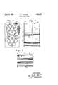
- Fig. 5 is an elevation, partly in section, 0f ⁇ an expansion chamber formed from a plurality of units, and illustrating the manner' in .which the capacity of the chamber can be varied at will by the aid of my invention;
- Fig. 6 is a side view, partly in section, of
- Fig. 7 is a sectional view taken .along plane 7-7 of Fig. 5. Y
- Fig. 1 the elements of the system are mainly diagrammaticallydisclosed, especial ly those that are shown. as mounted on a. base 11, which can rest, for example, on top of an ordinary ice box.
- a l complete circulatory s stem is disclosed for a refrigerant that is cyc ically permitted to expand, and is then compressed and condensed.
- the controlling device 16 is indicated as a float valve, which opens the connection between conduit 15 and a conduit 17, Whenever a definite amount of refrigerent accumulates in the float valve chamber.
- the refrigerant passes to an expansion chamber 18, the details of which will be later described. In this chamber, it vaporizes and rapidly absorbs heat.
- the conduit 17 connects to the inlet valve 19 of the chamber 18; and an outlet valve 2 is provided through which the vaporized refrigerant can pass up into a conduit .21.
- the valves 19 and 20 are arranged to be manually controlled, whereby it 1s possible to close them and to disconnect the chamber 18 for inspection or repairs or replacement.
- the vaporized refrigerant passes into the intake side of a compressor 22, which is directly connected in this instance to the, motor 14, and rests upon base 11.
- the compressor can be of any desired type. The compressor compresses the refrigerant which in its compressed state leaves the outlet side through.
- I utilize a cylindrical drumy or s ell 24, forming the main portion of the expansion chamber. It has two heads 25 and 26, shown in this instance as square, and which may be 4fastened to shell 24 as by'electricwelding.
- the square shape permits use of the heads for-supports for the entire chamber structure.
- the intake kvalve 19' is connected to theV interior of the drum 18 by the aid of a connections-27, which is arranged tangentially'withrespectto the drum, and is preferably welded therein.
- the tubes 29 have an outer peripheral surface enclosed in drum 24, and an inner surface open to the outside air, and forming cavities or recesses.
- the inner tube surfaces form a medium for a rapid and efficient heat .exchange, which can be' utilized to abstract heat from water placed in trays or containers 30 (Fig. 4). These trays have an overall length about the same as that of drum 24, and each has an ear or handle 31 making it easy to place them into tubes 29 andto remove them. It is advantageous to have the inner tube sur- .face closely confining the trays 30, see Fig. 3,
- Both units ⁇ 33 and 34 are similar to the expansion chamber shown in Figs. 2,3 and 4.
- the upper unit 33 has the inlet 38 and the outlet 39, similar to the connections'27 and A28'01" ,the-single form. Thereare two coni ⁇ nections between the two units.
- One is ashort straight pipe 40,V which is welded to both units and extends tangentially thereof. It is in about the same plane as the outlet 39.
- connection 41 is U-shaped, and also extends tangentiallyto both units in a plane near that of the intake 38.
- the arrangement can obviously be multiplied in order to take care of varying sizes ofinstallations.
- a larger number of units can be connected together for cooling a large space, like a displaylor show case, or an ice box for stores, clubs, or hotels.
- the small unit alone can be used for domestic v ice boxesv Qr the like.
- the important feature. is that -each unit has an element, such as heads 25 and 26, which have surfaces permittinga readyanesting thereof and simple mechanical connections and fastenings.
- a container for defining a space in which a refrigerant can expand characterized by the fact that supporting means are provided for the container for resting it on 'a surface, which means are so formed thatwhen a plurality of containers are nested ad-y ]acent one another'to form a series, the adjacent means have contiguous and contacting surfaces that can be fastened together in any appropriate manner.
- means for compressing a refrigerant means for condensing a refrigerant, means including a curved wall, defining a space in which refrig-l erant in the form of liquid expands'to form a gas, means whereby a volatile liquid refrigerant is directly led to the space from the condensing means without materially expanding unt-il it reaches the space, said means for leading the refrigerant.
- said space forming means including ⁇ a hollow container oflarge Volume, said container having a plurality of large'cavities, said ⁇ cavtieseach having an opening to the externalatmosphere, as well as a wall that is in directcontact with the refrigerant inthe. container, and a tray arranged to be inserted in-to the cavity forv holding material to be, cooled, said container thus forming a space inwhich substantially the entire refrigerating effect is secured,
- the materiahin the tray can be sub-y jected to rapid cooling.
- means for com pressing a refrigeran means for condensing a refrigerant means defining a' space 1n which refrigerant in the form of liquid expands to form a gas, means whereby a volatile liquid refrigerant is directly led to the space from the condensing means without materially ex-r l panding until ityreaches the space, said means for leadingthe refrigerant forming a substantially tangential opening into the space, means directly conducting the gaseous expanded refrigerant to the compressing means,
- said space forming means including-a hollow container of large volume, said container having one or more'large cavities, said cavities each having an opening t'o the external atmosphere, as well as a wallthat is in direct contact with the refrigerant in the container, said wall forming with the wall lof the con-A tainer a non-uniform passageway4 between them, and a tray arranged to be'lnser'ted 1nto,
- the cavity for holding material to be cooled said container thus forming a space in which substantially the entire refrigerating effect is secured, whereby the material in the tray can be subjected to rapid cooling.
- a refrigerator system ⁇ a compressor and a condenser, means forming an expansion chamber in which the refrigerant in the form of a liquid expands to form a gas
- said means comprising a. large chamber having cooling members formed therein, said mem- Y bers being arranged in -offsetvoverlying rela-v 1 tion,whereby due to the arrangement of the members the expanded gas is caused to follow a tortuous path throu h said chamber as and for the purpose speci ed.
- a compressor and a condenser means forming. an expansion chamber in which the refrigerant in the form of a liquid expands to form a gas, said means comprising a large chamber having a plurality of cooling members formed therein whereby the maximum cooling is obtained, said members beine arranged in overlying rows, each row being oiiset from its adjacent row, andthe members in each row being Oifset-from the members in the adjacent row,
Landscapes
- Engineering & Computer Science (AREA)
- Physics & Mathematics (AREA)
- Mechanical Engineering (AREA)
- Thermal Sciences (AREA)
- General Engineering & Computer Science (AREA)
- Devices That Are Associated With Refrigeration Equipment (AREA)
Description
pri i9? 193i w; FOURNESS REFRIGERATING SYSTEM Filed May 15` 1926 `2 Sheets-Sheet April 19, 1932.l -w. FOURNESS.
REFRIGERATING SYSTEM Filed May 15, 1926 z sheets-sheet I;
lis
Patented Apr, 19, 1932 UNrrEosTATEs PATENT 4o I-Flca wml-BED roURNEss, or PASADENA.- CALIFORNIA, AssIeNoa'BY ASSIGNMENTS, ro FoUaNEss DEVELOPMENT coEronA'rIoN L'rn., or NEW Yoan, N. LA conroEA- TION 0F NEW 'YORK BEFBIGERATING SYSTEM Application mea nay 15, 1'926. serial 110,109,306.
This invention relates to refrigeration, and more particularly to a system capable of use in connection with ice boxes in homes or stores, or with store display cabinets.
In the usual type of mechanical refrigeration, use is made of a fiuid refrigerant, which absorbs heat as it is allowed to expand in a space specifically provided for this purose. Mechanical work can then be perormed on the Huid after it is fully expanded and removed from the space, to compress it and thereby to abstract its heat content. It can then be recondensed, vand passed again to the expansion space to complete the cycle.,
It is thusevident that such systems have the following important elements operating upon the fluid: a compressor, a-condenser, and a space where the fluid is permitted to expand. Several different kinds of uids can be utilized for the refrigerant I have used sulphur dioxide.
It is common to provide the expansion space where the refrigerant absorbs heat, in
; in my system .the form of a long coil, placed adjacent the' elements that are to be kept cold. For example, it may be placed inside one of the comvpartments in an ordinary ice box, or around the interior of a show case that 'is to bekept cold. Such coils arey rather expensive to manufacture, and are difficult to replace or repair. It is accordingly one of the objects of my invention to provide a form of expansion chamber that is simple and inexpensive, and that obviates the undesirable coil construction. l
It is another object of my inventionto improve in general mechanical refrigeration systems; and specifically by providing an expansion space formed by any desired number of standard unit elements or containers.
It is still another object-of my invention to provide an expansion space of such form that it can very readily be placed in intimate heat exchanging relation with respect to receptacles for water, whereby thewater may be quickly frozen into small ice cubes for use in beverages. 'p i y My invention possesses many other advantages, and` has other objects which may bev made more easily apparent from a consideration of several embodiments of my invention. For this purpose I have shown a few forms in the drawings accompanying and forming part of the present specification. I shall now proceed to describe these forms in detail,
which illustrate the general principles of my invention; but it is to be understood. that this detailed desc'riptionis not to be taken in a llmitmg sense, since the scope of my invention is best defined by the appended claims.
Referring to the drawings:
Figure 1 is a diagrammatic view plete refrigerating system embodying one form of myvinvention; t
Fig. 2 is a view, mainly in section, of an expansion unit constructed in accordance Fig. 1;
Fig. 3 is a sectional view, taken ,along plane 3-3 of Fig. 2;
of a com- .with my invention and used in the system of Fig. 4 is a plan view of a water tray capable of use in connection -with my invention, for.-
forming small cubes of ice;
Fig. 5 is an elevation, partly in section, 0f` an expansion chamber formed from a plurality of units, and illustrating the manner' in .which the capacity of the chamber can be varied at will by the aid of my invention;
Fig. 6 is a side view, partly in section, of
vthe chamber shown in Fig. 5; and
Fig. 7 is a sectional view taken .along plane 7-7 of Fig. 5. Y
In Fig. 1, the elements of the system are mainly diagrammaticallydisclosed, especial ly those that are shown. as mounted on a. base 11, which can rest, for example, on top of an ordinary ice box. A l complete circulatory s stem is disclosed for a refrigerant that is cyc ically permitted to expand, and is then compressed and condensed. Thus a condensrefrigerant to the expansion space to be later descrlbed. In the present instance, the controlling device 16 is indicated as a float valve, which opens the connection between conduit 15 and a conduit 17, Whenever a definite amount of refrigerent accumulates in the float valve chamber.
The refrigerant thence passes to an expansion chamber 18, the details of which will be later described. In this chamber, it vaporizes and rapidly absorbs heat. The conduit 17 connects to the inlet valve 19 of the chamber 18; and an outlet valve 2 is provided through which the vaporized refrigerant can pass up into a conduit .21. The valves 19 and 20 are arranged to be manually controlled, whereby it 1s possible to close them and to disconnect the chamber 18 for inspection or repairs or replacement.
The vaporized refrigerant passes into the intake side of a compressor 22, which is directly connected in this instance to the, motor 14, and rests upon base 11. The compressor can be of any desired type. The compressor compresses the refrigerant which in its compressed state leaves the outlet side through.
pipe or conduit 23, and enters the condenser 12. Here it is li uefed and starts the cycle all over again, o2 expansion with attendant absorption of heat, compression and condensation.
The systemof refrigeration just described ture, however, resides in the particular man# ner in which the refrigerant is permitted to expand. In other Well-known systems, the
ex ansion takes place in a long coil or con-- du1t, the pressure in which, is controlled by an expansion valve or its equivalent. Such a coil necessarily permits a rather slowl rate of expansion, its passageway or bore being rather restricted;A and consequently the rate of cooling is low. One of the important features of my invention resides in making the expansion chamber of very large size in comparison with the connections leading into 1t.
Thus, as shown in Fi 2 and 3, I utilize a cylindrical drumy or s ell 24, forming the main portion of the expansion chamber. It has two heads 25 and 26, shown in this instance as square, and which may be 4fastened to shell 24 as by'electricwelding. The square shape permits use of the heads for-supports for the entire chamber structure. The intake kvalve 19' is connected to theV interior of the drum 18 by the aid of a connections-27, which is arranged tangentially'withrespectto the drum, and is preferably welded therein. vThe outlet valve 20 Vconnects toa similar connec tion 28; As thus far described, it is evident that the chamber V18 forms a very large space, into whchthe refrigerant is projected in a tan' y guita general, and its principles are wellgential direction directly from a comparatively small pipe. There is afforded every opportunity for immediate expansion and` consequent rapid absorption of heat. The
fact that a tangential dlrection is chosen for l the intake, ensures that 'little if any impediment or hindrance Will be opposed to the expansion, the vapor smoothly circulating around the drum 24.
It is desirable to provide a scheme for 29 extending into the drum 24 and preferablyv entirely across it between the heads 25 and 26. These tubes can be welded into these heads, so as to maintain the chamber 18 fluid tight. In this manner, the tubes 29 have an outer peripheral surface enclosed in drum 24, and an inner surface open to the outside air, and forming cavities or recesses. By the use of an expansion or cooling chamber embodying a plurality of cooling tubes, the cooling effect isgreatly speeded up and enhanced, due to the consequent in'crease of exposed cooling area. As the cooling area `is measured by the outer peripheral 'surface of the tubes'29 multiplied by the number of tubes, it is clearly apparent that the cooling area is directly dependent upon the number of cooling tubes employed. The inner tube surfaces form a medium for a rapid and efficient heat .exchange, which can be' utilized to abstract heat from water placed in trays or containers 30 (Fig. 4). These trays have an overall length about the same as that of drum 24, and each has an ear or handle 31 making it easy to place them into tubes 29 andto remove them. It is advantageous to have the inner tube sur- .face closely confining the trays 30, see Fig. 3,
as in this manner the maximum cooling eect vto surface tension. The air or gas entrapped b these bubbles form an insulating medlum a out the tubes which prevents the full effect. ofthe expanded coolingfluid thereon. It is also quite generally recognized that part of the refrigerant entering the chamber 24, through the inlet connection 27, does not immediately expandbut dropsin liquid form to the bottom of the chamber. `In dropping, the particles of liquid refrigerant entra some of the expanded refrigerant, orl as, an main.
tains' the entrapped gas at the ttom vof the follows the tortuous path defined by the off-v set tubes. The tubes also cause the expanded gas to follow a tortuous path through the chamber. 7
It is advantageous to prevent circulation of air through the passageways formed by tubes 29; and for'this .purpose a cover 32 is placed o ver one of the heads, such as 26, and
held theretol in anyappropriate fashion, as byscrews or welding.
' One of the advantages resultingfrom the form of expansion chamber is that itis a simple matter to nest a plurality of them together for increasing the capacity of the system. This lcan be done by placing them adjacent one another, either in a vertical or horizontal series, or both. Thus for example, I show in F-igs. 5, 6, and 7, details of a pair of chambers connected together to form a larger unit; one being shown as 33,
and the other as 34. They can be placed one above the other, and can be welded together by spot welding 35 at the adjacent surfaces of edges of the heads 36 and 37. These heads are merely placed one on top of each other. Both units`33 and 34 are similar to the expansion chamber shown in Figs. 2,3 and 4.
The upper unit 33 has the inlet 38 and the outlet 39, similar to the connections'27 and A28'01" ,the-single form. Thereare two coni` nections between the two units. One is ashort straight pipe 40,V which is welded to both units and extends tangentially thereof. It is in about the same plane as the outlet 39. The
The arrangement can obviously be multiplied in order to take care of varying sizes ofinstallations. For example, a larger number of units can be connected together for cooling a large space, like a displaylor show case, or an ice box for stores, clubs, or hotels.
The small unit alone can be used for domestic v ice boxesv Qr the like. The important feature. is that -each unit has an element, such as heads 25 and 26, which have surfaces permittinga readyanesting thereof and simple mechanical connections and fastenings.
-1. A container for defining a space in which a refrigerant can expand, characterized by the fact that supporting means are provided for the container for resting it on 'a surface, which means are so formed thatwhen a plurality of containers are nested ad-y ]acent one another'to form a series, the adjacent means have contiguous and contacting surfaces that can be fastened together in any appropriate manner.
2. In a refrigerator system, means for compressing a refrigerant, means for condensing a refrigerant, means including a curved wall, defining a space in which refrig-l erant in the form of liquid expands'to form a gas, means whereby a volatile liquid refrigerant is directly led to the space from the condensing means without materially expanding unt-il it reaches the space, said means for leading the refrigerant. forming a substanti'ally tangentialI opening through the curved wall into the space, means directly conducting the gaseous expanded refrigerant to the compressing means, said space forming meansincluding` a hollow container oflarge Volume, said container having a plurality of large'cavities, said `cavtieseach having an opening to the externalatmosphere, as well as a wall that is in directcontact with the refrigerant inthe. container, and a tray arranged to be inserted in-to the cavity forv holding material to be, cooled, said container thus forming a space inwhich substantially the entire refrigerating effect is secured,
l'whereby the materiahin the tray can be sub-y jected to rapid cooling.
3. In a refrigeraton system, means for com pressing a refrigeran means for condensing a refrigerant, means defining a' space 1n which refrigerant in the form of liquid expands to form a gas, means whereby a volatile liquid refrigerant is directly led to the space from the condensing means without materially ex-r l panding until ityreaches the space, said means for leadingthe refrigerant forming a substantially tangential opening into the space, means directly conducting the gaseous expanded refrigerant to the compressing means,
`said space forming means including-a hollow container of large volume, said container having one or more'large cavities, said cavities each having an opening t'o the external atmosphere, as well as a wallthat is in direct contact with the refrigerant in the container, said wall forming with the wall lof the con-A tainer a non-uniform passageway4 between them, and a tray arranged to be'lnser'ted 1nto,
the cavity for holding material to be cooled, said container thus forming a space in which substantially the entire refrigerating effect is secured, whereby the material in the tray can be subjected to rapid cooling.
4. In a refrigerator system,`a compressor and a condenser, means forming an expansion chamber in which the refrigerant in the form of a liquid expands to form a gas, said means comprising a. large chamber having cooling members formed therein, said mem- Y bers being arranged in -offsetvoverlying rela-v 1 tion,whereby due to the arrangement of the members the expanded gas is caused to follow a tortuous path throu h said chamber as and for the purpose speci ed.
5 5. In a refrigerator system, a compressor and a condenser, means forming. an expansion chamber in which the refrigerant in the form of a liquid expands to form a gas, said means comprising a large chamber having a plurality of cooling members formed therein whereby the maximum cooling is obtained, said members beine arranged in overlying rows, each row being oiiset from its adjacent row, andthe members in each row being Oifset-from the members in the adjacent row,
whereby due to the arrangement of the members the expanded gas is caused to follow a tortuous path through said chamber as andl for the purpose specified.
6. In the combination set out in claim 4 in which the chamber is in the Jform of a large tube, and in whichthe cooling members consist of tubes extending throughout the length ofthe large tube and secured thereto.
7. In the combination set out in claim 5 in which the chamber is in the form of a large tube, and in which the cooling members consist of tubes extending throughout the length of the large tube4 and secured thereto.
8. In the combination set out in claim5 in which the chamber lis in the form of a large tube, and in which the cooling members consist of tubes extending throughout the length of the large tube and secured thereto, said tubes closely confining a container adapted to be inserted therein, as and for the purpose specified. v
InI testimony whereof I have hereunto set myhand- 40 WILFRED FOURNESS.
Priority Applications (1)
| Application Number | Priority Date | Filing Date | Title |
|---|---|---|---|
| US109306A US1854466A (en) | 1926-05-15 | 1926-05-15 | Refrigerating system |
Applications Claiming Priority (1)
| Application Number | Priority Date | Filing Date | Title |
|---|---|---|---|
| US109306A US1854466A (en) | 1926-05-15 | 1926-05-15 | Refrigerating system |
Publications (1)
| Publication Number | Publication Date |
|---|---|
| US1854466A true US1854466A (en) | 1932-04-19 |
Family
ID=22326963
Family Applications (1)
| Application Number | Title | Priority Date | Filing Date |
|---|---|---|---|
| US109306A Expired - Lifetime US1854466A (en) | 1926-05-15 | 1926-05-15 | Refrigerating system |
Country Status (1)
| Country | Link |
|---|---|
| US (1) | US1854466A (en) |
-
1926
- 1926-05-15 US US109306A patent/US1854466A/en not_active Expired - Lifetime
Similar Documents
| Publication | Publication Date | Title |
|---|---|---|
| US3131553A (en) | Refrigeration system including condenser heat exchanger | |
| US3063259A (en) | Apparatus for filtering and dehydrating gases | |
| US2128794A (en) | Liquid cooler | |
| US1825731A (en) | Refrigerating apparatus | |
| US2505393A (en) | Combined filter, drier, heat exchanger, and surge resistor for electrical refrigerators | |
| US1854466A (en) | Refrigerating system | |
| US20220228781A1 (en) | Refrigerant processing unit, a method for evaporating a refrigerant and use of a refrigerant processing unit | |
| US2096075A (en) | Refrigeration apparatus | |
| US2726515A (en) | Self-contained heat exchange plates with electric resistance | |
| US2056022A (en) | Flow controlling device for refrigerating systems | |
| US1830022A (en) | Expansion valve control | |
| US2069630A (en) | Flow controlling device for refrigerating systems | |
| US1720768A (en) | Cooling unit for refrigerating mechanism | |
| US2009882A (en) | Refrigerant cooler | |
| US2188893A (en) | Refrigerating apparatus | |
| US2685778A (en) | Multiple stage refrigeration system | |
| US1934371A (en) | Mechanically refrigerated water cooler | |
| US2125727A (en) | Air conditioning apparatus | |
| US2088254A (en) | Cooling apparatus | |
| US2645908A (en) | Absorption refrigeration system of the inert gas type | |
| US2042418A (en) | Refrigerated beverage dispensing apparatus | |
| JPS5851581Y2 (en) | Refrigeration cycle high pressure side/low pressure side heat exchanger | |
| US2647377A (en) | Apparatus for providing gravity flow in flooded coil refrigeration systems | |
| US1531133A (en) | Vaporizer for refrigerating systems | |
| US462551A (en) | Fourths to james sinclair |