US1854463A - Treatment of hydrocarbon oil - Google Patents
Treatment of hydrocarbon oil Download PDFInfo
- Publication number
- US1854463A US1854463A US209632A US20963227A US1854463A US 1854463 A US1854463 A US 1854463A US 209632 A US209632 A US 209632A US 20963227 A US20963227 A US 20963227A US 1854463 A US1854463 A US 1854463A
- Authority
- US
- United States
- Prior art keywords
- line
- chamber
- vapors
- chambers
- oil
- Prior art date
- Legal status (The legal status is an assumption and is not a legal conclusion. Google has not performed a legal analysis and makes no representation as to the accuracy of the status listed.)
- Expired - Lifetime
Links
Images
Classifications
-
- C—CHEMISTRY; METALLURGY
- C10—PETROLEUM, GAS OR COKE INDUSTRIES; TECHNICAL GASES CONTAINING CARBON MONOXIDE; FUELS; LUBRICANTS; PEAT
- C10G—CRACKING HYDROCARBON OILS; PRODUCTION OF LIQUID HYDROCARBON MIXTURES, e.g. BY DESTRUCTIVE HYDROGENATION, OLIGOMERISATION, POLYMERISATION; RECOVERY OF HYDROCARBON OILS FROM OIL-SHALE, OIL-SAND, OR GASES; REFINING MIXTURES MAINLY CONSISTING OF HYDROCARBONS; REFORMING OF NAPHTHA; MINERAL WAXES
- C10G9/00—Thermal non-catalytic cracking, in the absence of hydrogen, of hydrocarbon oils
- C10G9/14—Thermal non-catalytic cracking, in the absence of hydrogen, of hydrocarbon oils in pipes or coils with or without auxiliary means, e.g. digesters, soaking drums, expansion means
Definitions
- Patented Apr. 19, 1932 range UNITED s'ra'rlzs- PATENT ,orr cr.
- the present invention relates to improvements in hydrocarbon oil conversion, and re-
- the invention is characterized by the fact sure or under superatmospheric pressure, but in either event it is preferable that the oil be subjected to conditions of cracking temperature whereby a substantial conversion takes place.
- the principal object of the present invention is to provide a process and apparatus having a wide range of flexibility, which process and apparatus are adapted to the efficient treatment of any character of charging stock including heavy crudes, topped crude, petroleum distillates and residue, and for the production of the desired types of products.
- Another objects of the invention are to provide aprocess and apparatus in which'the oil being treated, may be fractionally distilled and subjected to a cracking or breaking up, and to a polymerization to convert the heavier hydrocarbons into lighter hydrocarbons,
- the vapors and gases are subjected to progressively decreasing temperatures, the vapors and gases being preferably caused to percolate through the oil in the ing higher temperatures to; those wherein lower temperatures are maintained; to provide a method and ap aratus wherein the vapors, gases and ,liqui are brought into intimate contact with each other in zones of reaction; to provide a process andapparatus in which'the heavier products of the reaction are withdrawn and caused to be introduced into a zone of lower. temperature, assing successively back through zones 0 increasing temperature, being brou ht into contact therein with the li uid, am?
- the residue produced may comprise .a liquid, a semi liquid, a semi-solid or solid, that is, the conditions of operation may be controlled so as to produce liquid residue or non-liquid residue.
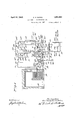
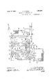
- Figs. 1 and 1a together form a diagrammatic side elevational view of apparatus in which the invention may be'carried out.
- 1 des'i nates the charging stock inlet line in whic may be interposed the pump 2.
- Line 3 controlled by valve 4 may branch out from the charging line 1, and a valve 5 may be interposed in line 1.
- Line 3 may have com munication with the first of a series of serially connected chambers 6, 7, Sand 9, which may comprise metal shells suitably insulated to prevent loss of heat by radiation, and provided with suitable cleaning manholes.
- All or a portion of it may be diverted by closing valve 4 and opening valve 5, in the line 10 in which may be interposed a valve 11, discharging the charging stock into the chamber 7 In either event, the
- Valves 28 and 29 may be interposed in the line 27, which line 27 communicates with the chamber 8.
- the line 27 communicates with a continuation of the line 22. Oil being introduced to the chamber 8 may overflow through any of the overflow lines 19 controlled by valves 20', said overflow lines 19 communicating with the header 21.
- the header 21 communicates with an extension of the line 22 in which is interposed the pump 23 controlled by valves 24, which pump may be by-passed through by-pass line 25 controlled by valve 26.
- the discharge of the pump 23 and the by-pass line 25 communicate with the line 27' in which are interposed the valves 28 and 29'.
- the line 27 communicates with chamber 9.
- the overflow from chamber 9 may pass out through any one or more of the overflow pipes 19" controlled by valves 20 discharging into the header 21 communicating with an extension of the line 22.
- the line 22 may feed unvaporized liquid to the heating coil 30 mounted in the furnace designated diagrammatically at 31.
- Adjacent to the entrance of the heating coil 30 a pump 32, controlled by valves 33, which may e by-passed through by-pass line 34 controlled by valve 35, may be interposed in the charging line 22.
- the oil is raised to a conversion temperature, and is discharged into the transfer line 36 which may discharge into a reaction chamber 37 either into the lower portion thereof through line 38 controlled by valve 39, or into the upper portion thereof throughline 4O controlled by valve 41.
- the chamber 37 ma be externally unheated, if
- vapors separate from the non-vaporous products of reaction, said vapors being removed through the line 42 in which may be interposed the valves 43, said vapor line 42 dis- 1,sae,eea
- Vapor pumps 44, 44, 44", 44 in by-pass lines 45, 45, etc. controlled by valves 46, 46, etc. may be interposed in the vapor lines 42, 42, 42 and 42 for the purpose of imposing a pump pressure on said vapors, if found desirable.
- the inlet from the vapor lines to each chamber maybe a point intermediate its height as illustrated, which point may be adjacent to the lower end of each chamber, if found desirable. It is important to note that the oil being introduced to the lines 10, 27 and 27 and into the chambers 7, 8
- vapors when introduced to the chamber should be introduced at a point just above the point of introduction of the oil, although it may be desired to vary this.
- Vapors remaining uncondensed after passagethrough the various chambers may be removed through the line 47, in which may be interposed the valve 48, the line 47 communicating with condenser coil 49 mounted in condenser box 50 wherein the vapors are condensed and passed to.
- a suitable receiver 51 which may be provided with gas relief line 52 controlled by valve 53.
- the receiver 51 may also be provided with liquid drawolf line 54 controlled by valve 55, as well as with distillate return line 56 in which maybe interposed the valve 57 and pump 58.
- the distillate return line 56 is utilized to return regulated portions of the distillate to the chamber 6 for the purpose of more completely dephlegmating the va'pors before they are removed through the vapor outlet 47, thus permitting the production of the so called end point distillate, that is, a distillate conforming generally .to commercial requirements for motor fuel, as to initial and end point range, gravity, etc.
- the charging stock is caused to pass successively through zones of progressively increasing temperature, countercurrent to the flow of the vapors with which said charging stock is brought into direct contact.
- the vapors are caused to percolate through a body of oil maintained therein,
- one of the desirable characteristics imparted to the distillate is that it makes it easier to subsequentl treat.
- I provide a vapor header 59controlled by valves 60 and connected by means of the branch 61 to each of the vapor transfer lines between adjacent chambers.
- any of the chambers may .be by-passed with regard to liquid by using the header 22 heretofore described, and closing and opening the necessary valves.
- the header 22 is provided with halves 62. 7
- Each of the chambers is provided with a drain 63 through which liquid or solids or both, may be removed. Valves 64 may be interposed in each of the drains 63.
- the desired valve or valves may be manipulated and the oil diverted through the line 65 controlled by the valves 66 merging with the'vapors being introduced through the vapor transfer line, thus bringing about an intermingling of the vapors and liquid prior to being introduced to the chamber.
- the depth of liquid-maintained in each of the chambers 7, Stand 9 is controlled by means of. the drawotfs 19, 19' and 19 respectively, the regulation of which depth also regulates the degreeof percolation, which thus controls the fractionation, heat exchange, reaction, and to a certain extent, the character of the final products.
- the preheated charging stock combines with the'condensate in each of the chambers, and passing L ber 7 as heretofore described, and are theresuccessively from chamber to chamber, the portions thereof remaining unvaporized, finally reach the heating coil 30.
- the charging stock is prefera lyi introduced directly from the charging header 22 into the heating coil 30 where said charging-stock is raised to a conversion temperature, being transferred to the reaction drum 37 where separation of vapors takes place, said vapors being initially mitting transfer of the vapors from the chamber 37 to the first chamber 9 of the series.
- the residue produced in the chamber37 may be withdrawn through any of the drawoff lines 71 controlled by valves 72, preferably the bottom line, and introduced into the header 73 which is provided with the drain 74 and valve 75.
- the valve 75 is closed, and said residue diverted through the line 76 to the chamber 7.
- Valves 77 and pump 78 may be interposed in the line 76.
- a by-pass 79 controlled by valve 80 may also be interposed in said line 76.
- the non-vaporous fractions are drawn off from the reaction chamber 37 before being permitted to be converted to' any substantial degree of coke.
- the residuum from the reaction chamber 37 is not introduced into the last chamber 6, in which purifying action of the vapors' is preferably allowed to take place. It is understood that should it be desirable, the residue may be introduced tothe last chamber, or to any of the other chambers; In this manner, the residuum free from heavier pitch and coke cbntaining products in I chamber 7 combines with the raw charging stock and condensate from the vapors in chamber 7, and passes out therefrom through any of the lines 19, and then by pipes 21 and 27 into the next preceding chamber as heretofore described. This is repeated for any one of the next preceding chambers.
- any heavy fractions contained in the residuum, and which would promote heavy formation of coke should they be retreated, separate from the relatively lighter portions of the residuum in the series of chambers 7 8 and 9, and the charging stock directed from the chamber 9 to the cracking coil 30 is relatively clean.
- the entire plant may be operated under atmospheric pressure, that is, only such pressure as is necessary to overcome frictional resistance being maintained, or certain parts of the plant may be maintained under superatmospheric pressure, which superatmospheric pressure may be uniform or differential pressures may be employed.
- valve 90 may connect with the line 7 6.
- a or heavy pitch is returned with the charging stock and condensate from the vapors 91 communicating with the line 76.
- the chargingstock is preferably introduced into and passed through the chambers where no residuum from the reaction chamber 37 is action chamber 37 will then be introduced 4 into chamber ⁇ 7 wherein it will be subjected to the scrubbing of the relatively cool vae pors therein, which willcause separation of the heav Y pitch carrying fractions and dilution o ,the residuum with the relatively light condensate, which will result in the production of a fluid residuum containing substantially no coke or sludge.
- the charging stocli'ma be assed through any desired number of c am ers, and similarly'any desired number of chambers can be utilized for purifying residuum.
- the residuum is withdrawn from chamber 7 or from the last of the chambers through which it was passed through drain line 63 and sent to storage.
- an umbrella shaped'shield may be provided immediately adjacent the discharge from-the vapor line illustrated diagrammatically at 94.
- any of the chambers may be cut out of operation, and bypassed by means of the valves in lines illustrated and described.
- the charging stock, and the residium, free of charging stock, from the reaction chamber 37 may be passed through the same or separate chambers, and the vapors may or may not be caused to percolate through any one of these chambers according to the result desired.
- a process for cracking oil comprising subjecting heavy oil to pressure distillation at a cracking temperature, causing substan-.
- vapors including heavier insufiiciently cracked fractions, separately removing unvaporized oil from said pressure distillation, subjecting said vapors to fractionation to condense heavier insu'fiiciently cracked fractions, subjecting said unvaporized oil independently of said vapors to further distillation by its contained heat'in a zone of reduced pressure, combining vapors resulting from said further distillation of the unvaporized oil with a fraction of vapors of likecharacter and containing heavier insufliciently cracked fractions taken off from the pressure distillation.
- a process for cracking oil comprising L subjecting heavy oil to pressure distillation at 3.
- a process for cracking hydrocarbon oil comprising maintaining a plurality of serially connected pools of oil, continuously supplying fresh charging oil to the pool at one end of the series, continuously removing unvaporized oil from the pool at the opposite end ofthe series, subjecting the removed unvaporized oil to a pressure distillation at a cracking temperature, separately removing .vapors and unvaporized residue from the pressure distillation zone, releasing further vapors from the unvaporized oil removed from the pressure distillation in a zone of reduced pressure, commingling the vapors re-' moved from the unvaporized residual oil in the zone of reduced pressure with vapors removed from the pressure distillation, percolating the resulting commingled vapors through certain of said serially connected pools of oil, subjecting the vapors which escape condensation bypercolation through said pools of oil to condensation and recovering the resulting distillate as the product of the process.
Landscapes
- Chemical & Material Sciences (AREA)
- Oil, Petroleum & Natural Gas (AREA)
- Physics & Mathematics (AREA)
- Thermal Sciences (AREA)
- Engineering & Computer Science (AREA)
- Chemical Kinetics & Catalysis (AREA)
- General Chemical & Material Sciences (AREA)
- Organic Chemistry (AREA)
- Production Of Liquid Hydrocarbon Mixture For Refining Petroleum (AREA)
- Organic Low-Molecular-Weight Compounds And Preparation Thereof (AREA)
Description
April 19, 1932. c. P. DUBBS TREATMENT OF HYDROC ARBON OIL Filed July 30, 1927 2 Sheets-Sheet l hfz tnes April 19, 1932; c. P. DUBBS TREATMENT OF HYDROCARBON OIL 2 Sheets-Sheet 2 Filed July 30. 1927 J72 J67: 1'07: Carbon Zfiubbs.
Patented Apr. 19, 1932 range UNITED s'ra'rlzs- PATENT ,orr cr.
CARBON P. DUBBS, OF WILMIETTE, ILLINOIS, ASSIGNCB TO UNIVEBBAL'OIL PRODUCTS COMPANY, OF CHICAGO, ILLINOIS, A CORPORATIONOF SOUTH DAKOTA that it can be operated at atmospheric pres- TREATMENT OF HYDROCARB ON OIL 1 Application filed July 80, 1927. Serial No. i093.
The present invention relates to improvements in hydrocarbon oil conversion, and re- The invention is characterized by the fact sure or under superatmospheric pressure, but in either event it is preferable that the oil be subjected to conditions of cracking temperature whereby a substantial conversion takes place.
The principal object of the present invention is to provide a process and apparatus having a wide range of flexibility, which process and apparatus are adapted to the efficient treatment of any character of charging stock including heavy crudes, topped crude, petroleum distillates and residue, and for the production of the desired types of products.
Other objects of the invention are to provide aprocess and apparatus in which'the oil being treated, may be fractionally distilled and subjected to a cracking or breaking up, and to a polymerization to convert the heavier hydrocarbons into lighter hydrocarbons,
such lighter oil being fractionally separated as one uninterrupted process, and during such process passing the released vapors and generated gases through the liquid body, thus various chambers, advancing from those havreducing the amount of uncondensable gases and coke; to provide a method and apparatus in which a series of chambers are employed, and in which the hydrocarbons treatediare subjected to progressively increasing temperatures; .to provide a method and apparatus in which. the vapors and gases are subjected to progressively decreasing temperatures, the vapors and gases being preferably caused to percolate through the oil in the ing higher temperatures to; those wherein lower temperatures are maintained; to provide a method and ap aratus wherein the vapors, gases and ,liqui are brought into intimate contact with each other in zones of reaction; to provide a process andapparatus in which'the heavier products of the reaction are withdrawn and caused to be introduced into a zone of lower. temperature, assing successively back through zones 0 increasing temperature, being brou ht into contact therein with the li uid, am? particularly with the vapors from w ich said heavier products of reaction were separated in a previous reaction zone; to provide a process and apparatus wherein the character and gravity of the residue produced, can be accurately controlled and regulatedyto'provide aprocess andapparatus of this general character in which by'controlling the conditions of o eration, the residue produced may comprise .a liquid, a semi liquid, a semi-solid or solid, that is, the conditions of operation may be controlled so as to produce liquid residue or non-liquid residue.
The utility of the invention, as well as other objects and advantages will hereafter more fully appear. v
Figs. 1 and 1a together form a diagrammatic side elevational view of apparatus in which the invention may be'carried out.
Referring in detail .to the drawings, 1 des'i nates the charging stock inlet line in whic may be interposed the pump 2. Line 3 controlled by valve 4 may branch out from the charging line 1, and a valve 5 may be interposed in line 1. Line 3 may have com munication with the first of a series of serially connected chambers 6, 7, Sand 9, which may comprise metal shells suitably insulated to prevent loss of heat by radiation, and provided with suitable cleaning manholes. Instead of feeding the charging stock into the chamber 6, all or a portion of it may be diverted by closing valve 4 and opening valve 5, in the line 10 in which may be interposed a valve 11, discharging the charging stock into the chamber 7 In either event, the
charging stock introduced to either the.
cooling medium, to condense the heavier fractions of'the vapors. Assume that charging stock has been introduced through the line 3 into the chamberfi wherein said oil was subjected to contact with vapors introduced from the chamber 7, the unvaporized charging stock together with reflux may be withdrawn through the line 12 and introduced to the line 10 if desired, under pressure imposed by the pump 13. The pump may be bypassed by opening valve 14 in line 15, and closing valve 16 in line 12. Line 10 may be provided with valves 17 and 18. The oil being introduced to the chamber 7 will build up to any desired level, controlled by means of the overflow pipes 19 in which may be interposed the valves 20 communicating with the header 21. The header 21 communicates with line 22 in which may be interposed the pump 23 controlled by valves 24. A hy-pass controlled by valve 26 may be interposed between the header 21 and the line 27 for the purpose of by-passing the pump 23, should it be desirable.
Valves 28 and 29 may be interposed in the line 27, which line 27 communicates with the chamber 8. The line 27 communicates with a continuation of the line 22. Oil being introduced to the chamber 8 may overflow through any of the overflow lines 19 controlled by valves 20', said overflow lines 19 communicating with the header 21. The header 21 communicates with an extension of the line 22 in which is interposed the pump 23 controlled by valves 24, which pump may be by-passed through by-pass line 25 controlled by valve 26. The discharge of the pump 23 and the by-pass line 25 communicate with the line 27' in which are interposed the valves 28 and 29'. The line 27 communicates with chamber 9. The overflow from chamber 9 may pass out through any one or more of the overflow pipes 19" controlled by valves 20 discharging into the header 21 communicating with an extension of the line 22. The line 22 may feed unvaporized liquid to the heating coil 30 mounted in the furnace designated diagrammatically at 31. Adjacent to the entrance of the heating coil 30 a pump 32, controlled by valves 33, which may e by-passed through by-pass line 34 controlled by valve 35, may be interposed in the charging line 22. During passage through the heating coil 30, the oil is raised to a conversion temperature, and is discharged into the transfer line 36 which may discharge into a reaction chamber 37 either into the lower portion thereof through line 38 controlled by valve 39, or into the upper portion thereof throughline 4O controlled by valve 41. The chamber 37 ma be externally unheated, if
' found more deslrable, in which event it may be insulated to prevent excess radiation of heat. Separation of the products of reaction I takes place in the chamber 37, that is, the
vapors separate from the non-vaporous products of reaction, said vapors being removed through the line 42 in which may be interposed the valves 43, said vapor line 42 dis- 1,sae,eea
charging into the first of the serially connected chambers 9.- Similar lines 42, 42 and 42 controlled by valves 43, 43" and 43' may pass the vapors respectively from chamber 9 through succeeding chambers 8, 7 and 6.
and 9 respectively, should be introduced ata point at which a volume of oil will be present in the chamber suliicient to permit separation of heavy hydrocarbons in semi-solid, or solid form.
It is also important to note that the vapors when introduced to the chamber, should be introduced at a point just above the point of introduction of the oil, although it may be desired to vary this.
Vapors remaining uncondensed after passagethrough the various chambers may be removed through the line 47, in which may be interposed the valve 48, the line 47 communicating with condenser coil 49 mounted in condenser box 50 wherein the vapors are condensed and passed to.a suitable receiver 51 which may be provided with gas relief line 52 controlled by valve 53. The receiver 51 may also be provided with liquid drawolf line 54 controlled by valve 55, as well as with distillate return line 56 in which maybe interposed the valve 57 and pump 58. The distillate return line 56 is utilized to return regulated portions of the distillate to the chamber 6 for the purpose of more completely dephlegmating the va'pors before they are removed through the vapor outlet 47, thus permitting the production of the so called end point distillate, that is, a distillate conforming generally .to commercial requirements for motor fuel, as to initial and end point range, gravity, etc.
In use and operation, the charging stock is caused to pass successively through zones of progressively increasing temperature, countercurrent to the flow of the vapors with which said charging stock is brought into direct contact. In each the chambers 6, 7, 8, and 9 the vapors are caused to percolate through a body of oil maintained therein,
its
beneficial characteristics to the products, for
. instance, one of the desirable characteristics imparted to the distillate is that it makes it easier to subsequentl treat.
Provision is made or by-passing any of the chambers, both with regard to liquid and regard to vapor. To cause a bypass of any of the chambers with regard to the vapor, I provide a vapor header 59controlled by valves 60 and connected by means of the branch 61 to each of the vapor transfer lines between adjacent chambers.
Any of the chambers may .be by-passed with regard to liquid by using the header 22 heretofore described, and closing and opening the necessary valves. To permit this, the header 22 is provided with halves 62. 7 Each of the chambers is provided with a drain 63 through which liquid or solids or both, may be removed. Valves 64 may be interposed in each of the drains 63.
Instead of'introducing the liquid from a preceding chamber or from the charging stock' supply line, into the chamber at the right hand side thereof as illustrated in the drawings, the desired valve or valves may be manipulated and the oil diverted through the line 65 controlled by the valves 66 merging with the'vapors being introduced through the vapor transfer line, thus bringing about an intermingling of the vapors and liquid prior to being introduced to the chamber.
The depth of liquid-maintained in each of the chambers 7, Stand 9 is controlled by means of. the drawotfs 19, 19' and 19 respectively, the regulation of which depth also regulates the degreeof percolation, which thus controls the fractionation, heat exchange, reaction, and to a certain extent, the character of the final products. In this manner, the preheated charging stock combines with the'condensate in each of the chambers, and passing L ber 7 as heretofore described, and are theresuccessively from chamber to chamber, the portions thereof remaining unvaporized, finally reach the heating coil 30. n
In starting u the operation, the charging stock is prefera lyi introduced directly from the charging header 22 into the heating coil 30 where said charging-stock is raised to a conversion temperature, being transferred to the reaction drum 37 where separation of vapors takes place, said vapors being initially mitting transfer of the vapors from the chamber 37 to the first chamber 9 of the series. At this time, the supply of charging stock di 55 rectl to the heatin coilsv is sto ped and y D P It is of importance to note that each of the chambers is cut into operation one at a time, and that the vapors and charging stock are introduced to that chamber at about the same time, It is of course obvious, that other methods of starting may be used, but it is thought well to illustrate one articular method which has been found satis actory.
After the plant is in operation, the residue produced in the chamber37 may be withdrawn through any of the drawoff lines 71 controlled by valves 72, preferably the bottom line, and introduced into the header 73 which is provided with the drain 74 and valve 75. In operation, the valve 75 is closed, and said residue diverted through the line 76 to the chamber 7. Valves 77 and pump 78 may be interposed in the line 76. A by-pass 79 controlled by valve 80 may also be interposed in said line 76. The non-vaporous fractions are drawn off from the reaction chamber 37 before being permitted to be converted to' any substantial degree of coke. This may be obtained by controlling the degreeof reaction The hot nonvaporous fractions from the chamber are then introduced into the chamby subjected to the cooling action due" to their commingling with the cooler charging stock introduced through the line 10 and with the vapors introduced through line 42". This cooling action stops any further reaction that might take place, in the residuum, and keeps the latter relatively free from heavy pitch,
coke and sludge. Furthermore, by commingling with the, relatively light vapors in chamber 7, the residuum is subjected to a diluting action from a part of these vapors, and
7 this tends to separate the lighter liquid por-' tions of said residue from the heavier pitch I of operation, the residuum from the reaction chamber 37 is not introduced into the last chamber 6, in which purifying action of the vapors' is preferably allowed to take place. It is understood that should it be desirable, the residue may be introduced tothe last chamber, or to any of the other chambers; In this manner, the residuum free from heavier pitch and coke cbntaining products in I chamber 7 combines with the raw charging stock and condensate from the vapors in chamber 7, and passes out therefrom through any of the lines 19, and then by pipes 21 and 27 into the next preceding chamber as heretofore described. This is repeated for any one of the next preceding chambers. In this manner, any heavy fractions contained in the residuum, and which would promote heavy formation of coke should they be retreated, separate from the relatively lighter portions of the residuum in the series of chambers 7 8 and 9, and the charging stock directed from the chamber 9 to the cracking coil 30 is relatively clean.
The entire plant may be operated under atmospheric pressure, that is, only such pressure as is necessary to overcome frictional resistance being maintained, or certain parts of the plant may be maintained under superatmospheric pressure, which superatmospheric pressure may be uniform or differential pressures may be employed. When the heating coil 30 and reaction chamber 37 are operated under pressure, it may be desirable to flash the residue withdrawn through the line 71 before being returned to the chamber, 7, in which event it is diverted from the line 7 6 to the line 81 controlled by valve 82, to the line 83 controlled by the valve 84; tov the flash chamber 85, the vapors released in flashing due to reduction in pressure, being removed through line 86 controlled by valve 87 and returned to any one of the chambers, for instance, chamber 9, a vapor pump such as illustrated at 88 being interposed in said line to supply the necessary pressure thereto or to chamber 8 through line 86 controlled by valve 87 The selection, of the chamber to which the vapors from the flashing of the.
residuum are returned, is such that the vapors from the next preceding higher tempera- .in the,
[ture chamber have approximately the same characteristics or are heavier than said vapors j from flashing. In this operation, only the heavier portion" of-the; residuum drawn ofi'.
It may be desirable in some instances, to supply the residue withdrawn through the :line 71 before it is returned to chamber 7, to a cooling action. To accomplish-this, I provide a continuation 91 of the line 81 controlled by the valves 92 in whichmay be interposed a cooler 93, the other end of said line. v
a or heavy pitch is returned with the charging stock and condensate from the vapors 91 communicating with the line 76.
the plant described in the foregoing specification, and illustrated in the drawings,
will of course, depend upon the kind of charging stock being treated, and the types of products desired. Where it is desirable to produce a normal yield of overhead products to be condensed as motor fuel, and it is further desired to produce a quantity of liquid residue for use as fuel or the like, the
operation may be carried out as follows: The chargingstock is preferably introduced into and passed through the chambers where no residuum from the reaction chamber 37 is action chamber 37 will then be introduced 4 into chamber\ 7 wherein it will be subjected to the scrubbing of the relatively cool vae pors therein, which willcause separation of the heav Y pitch carrying fractions and dilution o ,the residuum with the relatively light condensate, which will result in the production of a fluid residuum containing substantially no coke or sludge.
' The charging stocli'ma be assed through any desired number of c am ers, and similarly'any desired number of chambers can be utilized for purifying residuum. -The residuum is withdrawn from chamber 7 or from the last of the chambers through which it was passed through drain line 63 and sent to storage. I
' In this method .of operation, it is preferable to regulate the fractionation of the va. pors 1n the series of chambers 6, 7, 8 and 9 in condensation being effected in the'chambers where the residuum is purified. This is to decrease the proportion of condensate used purification and dilution of the residuum. 1
Another preferred method of operation consists in producing substantially no liquid residuum from the process, and in this operation the residuum drawnofi the chamber 37 is only the intermediatef'product. In this operation the residuum is returned into and throu h the chambers'r 7 ,'=8"' and 9 together with t e charging stoekfand passes through all the chambers. Depositioirtandseparation of the heavy coke andjpit clirfrom the re; sidum takesplace in thecha'mbersZ, 8 and and all portionsofthe residuum not sepa 4 rated in these chambers in the form of coke from each chamber to the next preceding higher temperature chamber, and thence through the heating coil to the reaction chamber 37, this operation being performed and continued until substantially all the charging stock has been converted into motor fuel and coke, and until the chambers are filled with solid residuum.
It is very important to 'notethat the vapors from the preceding chamber are introduced into the liquid body in a succeeding chamber in such a manner as to prevent any severe agitation in that chamber. To accomplish this, an umbrella shaped'shield may be provided immediately adjacent the discharge from-the vapor line illustrated diagrammatically at 94.
It will be apparent from the foregoing description of the process, it is extremely flexible and permits the use of any ty e of charging stock and the production 0 any type of products by regulation of the conditions of operation.
I intentionally do not wish to limit myself to any particular temperatures or pressures or yields, or to the type of charging stock and type of product which may be produced, as they may vary Widely Within the scope of the invention. Any of the chambers may be cut out of operation, and bypassed by means of the valves in lines illustrated and described. The charging stock, and the residium, free of charging stock, from the reaction chamber 37 may be passed through the same or separate chambers, and the vapors may or may not be caused to percolate through any one of these chambers according to the result desired. For instance, while I have heretofore described the percolation of the vapors through the chambers where the residium is passed, it is understood that this is not necessary, and the vapors may not be passed through said chamhers, which would then be used for coke separating chambers.
I claim as my invention:
1. A process for cracking oil comprising subjecting heavy oil to pressure distillation at a cracking temperature, causing substan-.
tial vaporization in and taking off vapors from said pressure distillation zone, said vapors including heavier insufiiciently cracked fractions, separately removing unvaporized oil from said pressure distillation, subjecting said vapors to fractionation to condense heavier insu'fiiciently cracked fractions, subjecting said unvaporized oil independently of said vapors to further distillation by its contained heat'in a zone of reduced pressure, combining vapors resulting from said further distillation of the unvaporized oil with a fraction of vapors of likecharacter and containing heavier insufliciently cracked fractions taken off from the pressure distillation.
2. A process for cracking oil comprising L subjecting heavy oil to pressure distillation at 3. A process for cracking hydrocarbon oilcomprising maintaining a plurality of serially connected pools of oil, continuously supplying fresh charging oil to the pool at one end of the series, continuously removing unvaporized oil from the pool at the opposite end ofthe series, subjecting the removed unvaporized oil to a pressure distillation at a cracking temperature, separately removing .vapors and unvaporized residue from the pressure distillation zone, releasing further vapors from the unvaporized oil removed from the pressure distillation in a zone of reduced pressure, commingling the vapors re-' moved from the unvaporized residual oil in the zone of reduced pressure with vapors removed from the pressure distillation, percolating the resulting commingled vapors through certain of said serially connected pools of oil, subjecting the vapors which escape condensation bypercolation through said pools of oil to condensation and recovering the resulting distillate as the product of the process.
In testimony whereof I aliix my signature.
CARBON P. DUBBS.
Priority Applications (1)
| Application Number | Priority Date | Filing Date | Title |
|---|---|---|---|
| US209632A US1854463A (en) | 1927-07-30 | 1927-07-30 | Treatment of hydrocarbon oil |
Applications Claiming Priority (1)
| Application Number | Priority Date | Filing Date | Title |
|---|---|---|---|
| US209632A US1854463A (en) | 1927-07-30 | 1927-07-30 | Treatment of hydrocarbon oil |
Publications (1)
| Publication Number | Publication Date |
|---|---|
| US1854463A true US1854463A (en) | 1932-04-19 |
Family
ID=22779582
Family Applications (1)
| Application Number | Title | Priority Date | Filing Date |
|---|---|---|---|
| US209632A Expired - Lifetime US1854463A (en) | 1927-07-30 | 1927-07-30 | Treatment of hydrocarbon oil |
Country Status (1)
| Country | Link |
|---|---|
| US (1) | US1854463A (en) |
-
1927
- 1927-07-30 US US209632A patent/US1854463A/en not_active Expired - Lifetime
Similar Documents
| Publication | Publication Date | Title |
|---|---|---|
| US2091261A (en) | Process for hydrocarbon oil conversion | |
| US1854463A (en) | Treatment of hydrocarbon oil | |
| US2105526A (en) | Process of hydrocarbon oil conversion | |
| US1860199A (en) | Method of cracking hydrocarbon oils | |
| US2139672A (en) | Combined liquid phase and vapor phase oil cracking process | |
| US2067810A (en) | Treatment of hydrocarbons | |
| US2224570A (en) | Treatment of hydrocarbon oils | |
| US1897577A (en) | Hydrocarbon oil conversion | |
| US2098033A (en) | Conversion and coking of hydrocarbons | |
| US1931757A (en) | Process for cracking hydrocarbon oils | |
| US1950058A (en) | Treating hydrocarbon oils | |
| US1811617A (en) | Process for treating petroleum oil | |
| US1799218A (en) | Hydrocarbon-oil conversion | |
| US2067832A (en) | Apparatus for converting higher boiling hydrocarbons into lower hydrocarbons | |
| US1946463A (en) | Process and apparatus for converting oils | |
| US1980839A (en) | Process of and apparatus for cracking hydrocarbon oils | |
| US1990868A (en) | Process for hydrocarbon oil conversion | |
| US2104418A (en) | Treatment of hydrocarbon oils | |
| US2119818A (en) | Apparatus and process for treating hydrocarbon oils | |
| US1861399A (en) | Art of oil conversion | |
| US1775067A (en) | Process for treating petroleum hydrocarbons | |
| US2158811A (en) | Conversion of hydrocarbon oils | |
| US2395081A (en) | Cracking and coking hydrocarbon oils | |
| US2056775A (en) | Art of hydrocarbon oil conversion | |
| US1551090A (en) | Process for treating hydrocarbons |