US1854446A - Package supporter and delivery mechanism - Google Patents
Package supporter and delivery mechanism Download PDFInfo
- Publication number
- US1854446A US1854446A US447927A US44792730A US1854446A US 1854446 A US1854446 A US 1854446A US 447927 A US447927 A US 447927A US 44792730 A US44792730 A US 44792730A US 1854446 A US1854446 A US 1854446A
- Authority
- US
- United States
- Prior art keywords
- rack bar
- supporting member
- gear
- supporting
- package
- Prior art date
- Legal status (The legal status is an assumption and is not a legal conclusion. Google has not performed a legal analysis and makes no representation as to the accuracy of the status listed.)
- Expired - Lifetime
Links
- 238000007599 discharging Methods 0.000 description 16
- 230000033001 locomotion Effects 0.000 description 13
- 238000009877 rendering Methods 0.000 description 3
- 238000010276 construction Methods 0.000 description 1
- 230000000694 effects Effects 0.000 description 1
- 239000012634 fragment Substances 0.000 description 1
- 230000004048 modification Effects 0.000 description 1
- 238000012986 modification Methods 0.000 description 1
- 230000000717 retained effect Effects 0.000 description 1
Images

Classifications
-
- B—PERFORMING OPERATIONS; TRANSPORTING
- B65—CONVEYING; PACKING; STORING; HANDLING THIN OR FILAMENTARY MATERIAL
- B65G—TRANSPORT OR STORAGE DEVICES, e.g. CONVEYORS FOR LOADING OR TIPPING, SHOP CONVEYOR SYSTEMS OR PNEUMATIC TUBE CONVEYORS
- B65G47/00—Article or material-handling devices associated with conveyors; Methods employing such devices
- B65G47/22—Devices influencing the relative position or the attitude of articles during transit by conveyors
- B65G47/26—Devices influencing the relative position or the attitude of articles during transit by conveyors arranging the articles, e.g. varying spacing between individual articles
- B65G47/28—Devices influencing the relative position or the attitude of articles during transit by conveyors arranging the articles, e.g. varying spacing between individual articles during transit by a single conveyor
- B65G47/29—Devices influencing the relative position or the attitude of articles during transit by conveyors arranging the articles, e.g. varying spacing between individual articles during transit by a single conveyor by temporarily stopping movement
Definitions
- My invention relates to a new and useful improvement in a package supporter and delivery mechanism adapted for use in stock rooms, stores, etc. where there is customarily placed on shelves a number of packages of goods which are removed from the shelves generally individually.
- Another object of the invention is the pro- 3 vision of means for preventing the passage of a higher package to the lower end of the inclined supporting member while the lowermost package is being displaced from the supporting member.
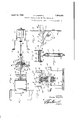
- Fig. 1 is a central sectional view of the invention viewed from the side.
- Fig. 2 is a view taken on line 2-2 of Fig. 1.
- Fig. 3 is an enlarged view taken on line 3-3 of Fig. 1.
- Fig. 4 is an enlarged side elevational view of a fragment of the invention.
- Fig. 5 is a view taken on line 55 of Fig. 1.
- Fig. 6 is an enlarged view taken on line 66 of Fig. 1.
- Fig. 7 is a view taken on line 77 of Fig. 1.
- the invention comprises an inclined supporting member or chute 11.
- Several chutes may be arranged in units positioned side by side so that when placed in a stock room or store they would be arranged along the side walls in the space which the shelves now customarilly use.
- This chute 11 is supported on suitable cross members 12 and 13 retained in position by the standards 14 and 15 which are -positi0ned at opposite sides of the chute and which are connected by cross bars 16 and 17, the cross bars themselves being connected by the bars 18.
- the base 19 is supported by the supporting standards 15 and the hanger 20.
- Mounted on and projecting upwardly from the base 19 are standards 21 having bearings 22 through which project and in which is journaled a shaft 23.
- the shaft 23 would, of course, be projected through bearings 22 positioned beneath each of the chutes or inclined supporting members 11.
- a gear 24 Fixedly mounted on and rotated with the shaft 23 is a gear 24 carrying at opposite faces the discs 25 and 26 which project beyond the periphery of the gear 24 and serve as guides.
- the shaft 23 is, when the device is in use, continuously rotating, the shaft 23 being rotated by a motor or any other suitable source of power.
- the bottom of the chute 11 is terminated as at 27 and the side walls 28 and 29 are continued to the end.
- lug portions 30 and 31 projected through which is the bolt 32' which extends through lugs 32 and 33 which project downwardly from the bottom extension 34, the end 35 of which is turned upwardly to serve as an engagement member or abutment for packages 36 which are loosely positioned on the inclined supporting member or chute.
- a spring 37 embracing the bolt 32' serves to normally retain the bottom extension'or discharging portion 34 in the position shown in full lines in Fig. 1.
- the rear end of the bottom extension 34 or discharging portion is curved downwardly to provide the arcuate portion 38 which, when the discharging portion or bottom extension 34 is moved to the dotted line position shown in Fig. 1, will prevent a package positioned above from sliding downwardly on the chute or inclined supporting member.
- a slot 39 is formed centrally in the rear- Ward arcuate portion 38 of the bottom extension 34 to accommodate the rack bar 40 which is pivotally connected at one end to the lugs 41 which projectfromthe bottom of the member 34.
- This rack bar projects rearwardly in alignment with the gear 24 and extends between the hanger 20 at a central ofi'set portion and the plate 41 which is secured thereto, this plate 41' and theofi'set portion of the hanger 20 serving to provide a guide loop through which the rack bar 40 slidably projects.
- rollers 48 and 49 which are adapted to engage either the upper or the lower face of the'blocks 44 and 45 when the rack bar 40 is moved longitudinally.
- U shaped supporting bracket 50 Secured to and projecting rearwardly from the standards 14 is a U shaped supporting bracket 50 to which is secured the U shaped bracket 51 serving as a support for the magnetic coil 52 connected by the wires 53 and 54 to a suitable source of electrical energy.
- a switch 55 is interposed in this circuit and this switch may be of a type which is normally held by a spring in open position, the switch being located in a position easily accessible to the clerk in the store or other person who is intended to operate the device and release packages from the chute or supporting member 11.
- a longitudinally movable core 56 is nor mally held by the resilient contact arm 57 and the spring 58 in outwardly pressed position as shown in Fig. 1 so as to engage the undersurface of the rack bar 40 and hold it in a position where it will not mesh with the gear 24.
- the core 56 When the coil 52 is energized, the core 56 will be retracted to the dotted line position shown in Fig. 1 thus permitting the rack bar 40 to fall downwardly so as to engage and mesh with the locating gear 24. The rack bar will then be moved forwardly to the dotted line position causing a tilting of the bottom extension 34 to the dotted line position so as to discharge the lowermost package on the chute.
- An endless conveyor 59 of any desired type is positioned beneath the lower end of the chute so that the discharged package may fall thereon and be conveyed to any desired location such as a wrapping counter or the like.
- the clerk may wait on the customer at the wrapping counter and the switches 55 be positioned in easy reach of the clerk and by closing the various switches to the various chutes the packages desired by the customer will be delivered by the endless conveyor to the wrapping counter.
- the rack bar moves forwardly after meshing with the gear 24 the rollers 48 and 49 will engage the upper face of the blocks 44 and 45 thus holding the rack bar 40 down in mesh with the gear 24.
- the leaf springs 60 and 61 will be engaged by the pins 42 and 43 and flexed into the dotted line position shown in Fig. 1.
- the teeth 62 which are higher than the remaining teeth 63 on the rack bar 40 will engage the gear 2'4 and raise the rack bar out of mesh with the gear 24.
- the leaf springs 60 and 61 will also assist in this raising of the rack bar 40 and assist in the rearward movement of the rack bar 40 as the bottom extension 34 returns to its normal position shown in full lines in Fig. 1.
- rollers 48 and 49 will then he engaged by the undersurface of the blocks 44 and 45 and the core 56 will have been re turned to the position shown in full lines in Fig. 1 so that the rear end of the rack bar 40. will engage on its undersurface the end of the core 56.
- the action is a comparatively quick action depending upon the speed of rotation of the gear 24 in the forward move-- ment of the rack bar 40 but the return action is quite rapid as the springs 37, 60, and 61 are of sufficient tension to effect a rapid return.
- a roller 64 is mounted between the offset portion of the standard 20 and the plate 41' to prevent an excessive upward tilting of the rack bar 40 in its return movement.
- a device of the class described comprising: an inclined supporting member adapted for the reception of articles positioned loosely thereon; a movable engagement member for engaging when in operative position the lowermost of said articles on said supporting member and preventing the passage of said article from said supporting member; a movable engagement member engageable when in operative position for engaging the article adjacent the lowermost of said articles on said supporting member and preventing its passage downwardly of said supporting member; means for simultaneously moving said first mentioned engagement member to inoperative position and said second mentioned engagement member to operative position; resilient means for returning said engagement members to the positions from which moved; means for automatically rendering said moving means inoperative upon movement of said first mentioned engagement member to inoperative position; and releasable means for retaining said moving means in inoperative position.
- a device of the class described comprising: an inclined supporting member adapted for the reception of articles positioned loosely thereon; a movable engagement member for engaging when in operative position the lowermost of said articles on said supporting member and preventing the passage of said article from said supporting m ember; a movable engagement member engageable when in operative pos tion for engaging the article adjacent the lowermost of said articles on said supporting member and preventing its passage downwardly of said supporting member; means for simultaneously moving said first mentioned engagement member to inoperative position and said second mentioned engagement member to operative position: resilient means for returning said engagement members to the positions from which moved; means for automatically rendering said moving means inoperative upon movement of said first mentioned engagement member to inoperative position; and electricallv operated releasable means for retaining said moving means in inoperative position.
- a device of the class described comprising: a supporting member; a swingably mounted supporting port on on one end of said supporting member adapted upon movement into one position for discharging therefrom an article loosely positioned thereon; means for moving said supporting portion to discharging position; means for render ng said moving means inoperative upon swinging of said portion to discharging position; and releasable means for retaining said moving means in inoperative position upon return of said portion to normal position.
- a device of the class described comprising: a supporting member; a swingably mounted supporting portion on one end of said supporting member adapted upon movement into one position for discharging therefrom an article loosely positioned thereon; means for moving said supporting portion to discharging position; means for rendering said moving means inoperative upon swinging of said portion to discharging position; releasable means for retaining said moving means in inoperative position upon return of said portion to normal position; and resilient means for returning said portion to normal position.
- a device of the class described comprising: a supporting member; a swingably mounted supporting portion on one end of said supporting member swingable into one position for discharging therefrom an article loosely positioned thereon; resilient means for normally retaining said portion in nondischarging position; a rack bar swingably connected at one end to said portion and adapted upon movement in one direction for swinging said portion to discharging position; a rotatable gear engageable with said rack bar for moving the same in said direction; releasable means for retaining said rack bar in elevated relation to said gear.
- a device of the class described comprising: a supporting member; a swingably mounted supporting portion on one end of said supporting member swingable into one position for discharging therefrom an article loosely positioned thereon; resilient means for normally retaining said portion in non-discharging position; a rack bar swingably connected at one end to said portion and adapted upon movement in one direction for swinging said portion to discharging position; a rotatable gear engageable with said rack bar for moving the same in said direction; releasable means for retaining said rack bar in elevated relation to said gear; and means upon release of said rack bar from inoperative position for retaining said rack bar in engagement with said gear during movement of said rack bar in said direction.
- a device of the class described comprising: a supporting member; a swingably mounted supporting portion on one end of said supporting member swingable into one position for discharging therefrom an article loosely positioned thereon; resilient means for normally retaining said portion in nondischarging position; a rack bar swingably connected at one end to said portion and adapted upon movement in one direction for swinging said portion to discharging position; a rotatable gear engageable with said rack bar for moving the same in said direction; releasable means for retaining said rack bar in elevated relation to said gear; means upon release of said rack bar from inoperative position for retaining said rack bar in engagement with said gear during movement of said rack bar in said direction; and means operative for raising said rack bar out of engagement with said gear upon movement of said rack bar in said direction a predetermined distance.
Landscapes
- Engineering & Computer Science (AREA)
- Mechanical Engineering (AREA)
- Warehouses Or Storage Devices (AREA)
Description
Aprnl 19, 1932. D CAMPBELL PACKAGE SUPPORTER AND DELIVERY MECHANISM Filed April 28, 1930 2 Sheets-Sheet ATTORNEY.
April 19, 1932. D. CAMPBELL PACKAGE SUPPQRTER AND DELIVERY MECHANISM Filed April 28, 1930 2 Sheets-Sheet l. M y. W mw m D Patented Apr. 19, 1932 DUNCAN CAMPBELL, OF DETROIT, MICHIGAN PACKAGE SUPPORTER AND DELIVERY MECHANISM Application filed April 28, 1930. Serial No. 447,927.
My invention relates to a new and useful improvement in a package supporter and delivery mechanism adapted for use in stock rooms, stores, etc. where there is customarily placed on shelves a number of packages of goods which are removed from the shelves generally individually.
It is an object of the present invention to provide a support for such packages, and
mechanism so constructed and arranged that the packages may be easily and quickly removed from the supporting member individually with a minimum amount of manual effort.
It is another object of the present invention to provide a plurality of inclined supporting members for supporting indivldual articles and mechanism operable at will for permitting the individual passage of said packages from said supporting member by grav- Another object of the invention is the provision of an inclined supporting member provided at its lower end with an engagement member which may be easily and quickly moved to inoperative position to permit the passage of a package from the supporting member.
Another object of the invention is the pro- 3 vision of means for preventing the passage of a higher package to the lower end of the inclined supporting member while the lowermost package is being displaced from the supporting member.
Other objects will appear hereinafter.
The invention consists in the combination and arrangement of parts hereinafter described and claimed.
The invention will be best understood by a reference to the accompanying drawings which form a part of this specification and in which,
Fig. 1 is a central sectional view of the invention viewed from the side.
Fig. 2 is a view taken on line 2-2 of Fig. 1.
Fig. 3 is an enlarged view taken on line 3-3 of Fig. 1.
Fig. 4 is an enlarged side elevational view of a fragment of the invention.
Fig. 5 is a view taken on line 55 of Fig. 1.
Fig. 6 is an enlarged view taken on line 66 of Fig. 1.
Fig. 7 is a view taken on line 77 of Fig. 1.
The invention comprises an inclined supporting member or chute 11. Several chutes may be arranged in units positioned side by side so that when placed in a stock room or store they would be arranged along the side walls in the space which the shelves now customarilly use. This chute 11 is supported on suitable cross members 12 and 13 retained in position by the standards 14 and 15 which are -positi0ned at opposite sides of the chute and which are connected by cross bars 16 and 17, the cross bars themselves being connected by the bars 18. The base 19 is supported by the supporting standards 15 and the hanger 20. Mounted on and projecting upwardly from the base 19 are standards 21 having bearings 22 through which project and in which is journaled a shaft 23. Where the device is arranged in units with a plurality of chutes or inclined supporting members 0- sitioned side by side, the shaft 23 would, of course, be projected through bearings 22 positioned beneath each of the chutes or inclined supporting members 11.
Fixedly mounted on and rotated with the shaft 23 is a gear 24 carrying at opposite faces the discs 25 and 26 which project beyond the periphery of the gear 24 and serve as guides. The shaft 23 is, when the device is in use, continuously rotating, the shaft 23 being rotated by a motor or any other suitable source of power. The bottom of the chute 11 is terminated as at 27 and the side walls 28 and 29 are continued to the end. Depending from the side walls 28 and 29 are lug portions 30 and 31 projected through which is the bolt 32' which extends through lugs 32 and 33 which project downwardly from the bottom extension 34, the end 35 of which is turned upwardly to serve as an engagement member or abutment for packages 36 which are loosely positioned on the inclined supporting member or chute. A spring 37 embracing the bolt 32' serves to normally retain the bottom extension'or discharging portion 34 in the position shown in full lines in Fig. 1. The rear end of the bottom extension 34 or discharging portion is curved downwardly to provide the arcuate portion 38 which, when the discharging portion or bottom extension 34 is moved to the dotted line position shown in Fig. 1, will prevent a package positioned above from sliding downwardly on the chute or inclined supporting member. v
A slot 39 is formed centrally in the rear- Ward arcuate portion 38 of the bottom extension 34 to accommodate the rack bar 40 which is pivotally connected at one end to the lugs 41 which projectfromthe bottom of the member 34. This rack bar projects rearwardly in alignment with the gear 24 and extends between the hanger 20 at a central ofi'set portion and the plate 41 which is secured thereto, this plate 41' and theofi'set portion of the hanger 20 serving to provide a guide loop through which the rack bar 40 slidably projects.
Projecting from opposite sides of the rack bar 40 are the pins 42 and 43. Mounted on opposite faces of the rack bar 40 rearwardly of the pins 42 and 43 are plates 44 and 45. Rotatably mounted on the upwardly projecting standards 46 and 47 are rollers 48 and 49 which are adapted to engage either the upper or the lower face of the'blocks 44 and 45 when the rack bar 40 is moved longitudinally.
Secured to and projecting rearwardly from the standards 14 is a U shaped supporting bracket 50 to which is secured the U shaped bracket 51 serving as a support for the magnetic coil 52 connected by the wires 53 and 54 to a suitable source of electrical energy. A switch 55 is interposed in this circuit and this switch may be of a type which is normally held by a spring in open position, the switch being located in a position easily accessible to the clerk in the store or other person who is intended to operate the device and release packages from the chute or supporting member 11.
A longitudinally movable core 56 is nor mally held by the resilient contact arm 57 and the spring 58 in outwardly pressed position as shown in Fig. 1 so as to engage the undersurface of the rack bar 40 and hold it in a position where it will not mesh with the gear 24.
When the coil 52 is energized, the core 56 will be retracted to the dotted line position shown in Fig. 1 thus permitting the rack bar 40 to fall downwardly so as to engage and mesh with the locating gear 24. The rack bar will then be moved forwardly to the dotted line position causing a tilting of the bottom extension 34 to the dotted line position so as to discharge the lowermost package on the chute.
An endless conveyor 59 of any desired type is positioned beneath the lower end of the chute so that the discharged package may fall thereon and be conveyed to any desired location such as a wrapping counter or the like. Where the arrangement is installed in a grocery store, the clerk may wait on the customer at the wrapping counter and the switches 55 be positioned in easy reach of the clerk and by closing the various switches to the various chutes the packages desired by the customer will be delivered by the endless conveyor to the wrapping counter.
WVhen the rack bar moves forwardly after meshing with the gear 24 the rollers 48 and 49 will engage the upper face of the blocks 44 and 45 thus holding the rack bar 40 down in mesh with the gear 24. At the same time the leaf springs 60 and 61 will be engaged by the pins 42 and 43 and flexed into the dotted line position shown in Fig. 1. After the blocks 44 and 45 ride out of engagement with the rollers 48 and 49, the teeth 62 which are higher than the remaining teeth 63 on the rack bar 40 will engage the gear 2'4 and raise the rack bar out of mesh with the gear 24. The leaf springs 60 and 61 will also assist in this raising of the rack bar 40 and assist in the rearward movement of the rack bar 40 as the bottom extension 34 returns to its normal position shown in full lines in Fig. 1. The rollers 48 and 49 will then he engaged by the undersurface of the blocks 44 and 45 and the core 56 will have been re turned to the position shown in full lines in Fig. 1 so that the rear end of the rack bar 40. will engage on its undersurface the end of the core 56. The action is a comparatively quick action depending upon the speed of rotation of the gear 24 in the forward move-- ment of the rack bar 40 but the return action is quite rapid as the springs 37, 60, and 61 are of sufficient tension to effect a rapid return.
A roller 64 is mounted between the offset portion of the standard 20 and the plate 41' to prevent an excessive upward tilting of the rack bar 40 in its return movement.
It is believed evident that the operator by closing and opening the switch 55 may suecessively deliver from the same chute a number of packages.
While I have illustrated and described the preferred form of construction of my invention, I do not wish to limit myself to the precise details of structure shown but desire to avail myself of such variations and modifications as may come within the scope of the appended claims.
Having thus described my invention, what I claim as new and desire to secure by Letters Patent is: v
1. A device of the class described, comprising: an inclined supporting member adapted for the reception of articles positioned loosely thereon; a movable engagement member for engaging when in operative position the lowermost of said articles on said supporting member and preventing the passage of said article from said supporting member; a movable engagement member engageable when in operative position for engaging the article adjacent the lowermost of said articles on said supporting member and preventing its passage downwardly of said supporting member; means for simultaneously moving said first mentioned engagement member to inoperative position and said second mentioned engagement member to operative position; resilient means for returning said engagement members to the positions from which moved; means for automatically rendering said moving means inoperative upon movement of said first mentioned engagement member to inoperative position; and releasable means for retaining said moving means in inoperative position.
2. A device of the class described, comprising: an inclined supporting member adapted for the reception of articles positioned loosely thereon; a movable engagement member for engaging when in operative position the lowermost of said articles on said supporting member and preventing the passage of said article from said supporting m ember; a movable engagement member engageable when in operative pos tion for engaging the article adjacent the lowermost of said articles on said supporting member and preventing its passage downwardly of said supporting member; means for simultaneously moving said first mentioned engagement member to inoperative position and said second mentioned engagement member to operative position: resilient means for returning said engagement members to the positions from which moved; means for automatically rendering said moving means inoperative upon movement of said first mentioned engagement member to inoperative position; and electricallv operated releasable means for retaining said moving means in inoperative position.
3. A device of the class described, comprising: a supporting member; a swingably mounted supporting port on on one end of said supporting member adapted upon movement into one position for discharging therefrom an article loosely positioned thereon; means for moving said supporting portion to discharging position; means for render ng said moving means inoperative upon swinging of said portion to discharging position; and releasable means for retaining said moving means in inoperative position upon return of said portion to normal position.
4. A device of the class described, comprising: a supporting member; a swingably mounted supporting portion on one end of said supporting member adapted upon movement into one position for discharging therefrom an article loosely positioned thereon; means for moving said supporting portion to discharging position; means for rendering said moving means inoperative upon swinging of said portion to discharging position; releasable means for retaining said moving means in inoperative position upon return of said portion to normal position; and resilient means for returning said portion to normal position.
5. A device of the class described, comprising: a supporting member; a swingably mounted supporting portion on one end of said supporting member swingable into one position for discharging therefrom an article loosely positioned thereon; resilient means for normally retaining said portion in nondischarging position; a rack bar swingably connected at one end to said portion and adapted upon movement in one direction for swinging said portion to discharging position; a rotatable gear engageable with said rack bar for moving the same in said direction; releasable means for retaining said rack bar in elevated relation to said gear.
6. A device of the class described, comprising: a supporting member; a swingably mounted supporting portion on one end of said supporting member swingable into one position for discharging therefrom an article loosely positioned thereon; resilient means for normally retaining said portion in non-discharging position; a rack bar swingably connected at one end to said portion and adapted upon movement in one direction for swinging said portion to discharging position; a rotatable gear engageable with said rack bar for moving the same in said direction; releasable means for retaining said rack bar in elevated relation to said gear; and means upon release of said rack bar from inoperative position for retaining said rack bar in engagement with said gear during movement of said rack bar in said direction.
7. A device of the class described, comprising: a supporting member; a swingably mounted supporting portion on one end of said supporting member swingable into one position for discharging therefrom an article loosely positioned thereon; resilient means for normally retaining said portion in nondischarging position; a rack bar swingably connected at one end to said portion and adapted upon movement in one direction for swinging said portion to discharging position; a rotatable gear engageable with said rack bar for moving the same in said direction; releasable means for retaining said rack bar in elevated relation to said gear; means upon release of said rack bar from inoperative position for retaining said rack bar in engagement with said gear during movement of said rack bar in said direction; and means operative for raising said rack bar out of engagement with said gear upon movement of said rack bar in said direction a predetermined distance.
In testimony whereof I have signed the foregoing specification.
DUNCAN CAMPBELL.
Priority Applications (1)
| Application Number | Priority Date | Filing Date | Title |
|---|---|---|---|
| US447927A US1854446A (en) | 1930-04-28 | 1930-04-28 | Package supporter and delivery mechanism |
Applications Claiming Priority (1)
| Application Number | Priority Date | Filing Date | Title |
|---|---|---|---|
| US447927A US1854446A (en) | 1930-04-28 | 1930-04-28 | Package supporter and delivery mechanism |
Publications (1)
| Publication Number | Publication Date |
|---|---|
| US1854446A true US1854446A (en) | 1932-04-19 |
Family
ID=23778300
Family Applications (1)
| Application Number | Title | Priority Date | Filing Date |
|---|---|---|---|
| US447927A Expired - Lifetime US1854446A (en) | 1930-04-28 | 1930-04-28 | Package supporter and delivery mechanism |
Country Status (1)
| Country | Link |
|---|---|
| US (1) | US1854446A (en) |
Cited By (8)
| Publication number | Priority date | Publication date | Assignee | Title |
|---|---|---|---|---|
| US2450249A (en) * | 1943-04-13 | 1948-09-28 | Murphy Automatic Pinsetter Co | Automatic pin setting machine |
| US2523711A (en) * | 1945-12-08 | 1950-09-26 | Western Electric Co | Dispensing apparatus |
| US2571365A (en) * | 1950-04-04 | 1951-10-16 | Exhibit Supply Company | Puck delivering device |
| US2577394A (en) * | 1946-06-11 | 1951-12-04 | Zunino Carl | Dispensing machine |
| US2623694A (en) * | 1947-02-26 | 1952-12-30 | Automatic Elect Lab | Merchandise dispensing and recording system |
| US2926815A (en) * | 1955-10-11 | 1960-03-01 | Hanley W Wolf | Conveyor release mechanism |
| US3160260A (en) * | 1961-02-01 | 1964-12-08 | Cherry Burrell Corp | Apparatus for handling stacked contaziners |
| US5700125A (en) * | 1996-03-27 | 1997-12-23 | Storage Technology Corporation | Gravity feed pass-thru port for automated cartridge library |
-
1930
- 1930-04-28 US US447927A patent/US1854446A/en not_active Expired - Lifetime
Cited By (8)
| Publication number | Priority date | Publication date | Assignee | Title |
|---|---|---|---|---|
| US2450249A (en) * | 1943-04-13 | 1948-09-28 | Murphy Automatic Pinsetter Co | Automatic pin setting machine |
| US2523711A (en) * | 1945-12-08 | 1950-09-26 | Western Electric Co | Dispensing apparatus |
| US2577394A (en) * | 1946-06-11 | 1951-12-04 | Zunino Carl | Dispensing machine |
| US2623694A (en) * | 1947-02-26 | 1952-12-30 | Automatic Elect Lab | Merchandise dispensing and recording system |
| US2571365A (en) * | 1950-04-04 | 1951-10-16 | Exhibit Supply Company | Puck delivering device |
| US2926815A (en) * | 1955-10-11 | 1960-03-01 | Hanley W Wolf | Conveyor release mechanism |
| US3160260A (en) * | 1961-02-01 | 1964-12-08 | Cherry Burrell Corp | Apparatus for handling stacked contaziners |
| US5700125A (en) * | 1996-03-27 | 1997-12-23 | Storage Technology Corporation | Gravity feed pass-thru port for automated cartridge library |
Similar Documents
| Publication | Publication Date | Title |
|---|---|---|
| US2832506A (en) | Dispensing machine | |
| US2893596A (en) | Sandwich merchandising machine | |
| US3591045A (en) | Helical coil vending machine | |
| US1854446A (en) | Package supporter and delivery mechanism | |
| US2380093A (en) | Dispensing machine | |
| US2806631A (en) | Automatic merchandising unit | |
| US2628875A (en) | Vending or dispensing machine for cylindrical containers | |
| US3502382A (en) | Dispensing apparatus mechanism for shifting articles from storage to discharge position | |
| US2616776A (en) | Vending machine | |
| US3464589A (en) | Serpentine can vender mechanism | |
| US3160315A (en) | Book vending machine | |
| US3028045A (en) | Package vending machine | |
| US3678660A (en) | Unload, check, and bag apparatus for supermarkets | |
| US3109515A (en) | Check out counter | |
| US2644735A (en) | Package vending machine with dual conveyers arranged for alternate delivery | |
| US2128179A (en) | Dispensing machine | |
| US2789726A (en) | Dispensing machine | |
| US2837237A (en) | Vending machine | |
| US3175728A (en) | Cam plate dispensing mechanism | |
| US3319797A (en) | Ball cart | |
| US2176394A (en) | Vending machine | |
| US2888166A (en) | Elevating column console cigarette merchandising machine | |
| US2916186A (en) | Dispensing machine for heavy articles | |
| US2957603A (en) | Cartoned merchandise vending machine | |
| US3319798A (en) | Ball cart |