US1854444A - Airplane wing construction - Google Patents
Airplane wing construction Download PDFInfo
- Publication number
- US1854444A US1854444A US389932A US38993229A US1854444A US 1854444 A US1854444 A US 1854444A US 389932 A US389932 A US 389932A US 38993229 A US38993229 A US 38993229A US 1854444 A US1854444 A US 1854444A
- Authority
- US
- United States
- Prior art keywords
- wing
- airfoil
- shiftable
- pivoted
- rigid
- Prior art date
- Legal status (The legal status is an assumption and is not a legal conclusion. Google has not performed a legal analysis and makes no representation as to the accuracy of the status listed.)
- Expired - Lifetime
Links
- 238000010276 construction Methods 0.000 title description 11
- 230000000694 effects Effects 0.000 description 6
- RTZKZFJDLAIYFH-UHFFFAOYSA-N Diethyl ether Chemical compound CCOCC RTZKZFJDLAIYFH-UHFFFAOYSA-N 0.000 description 4
- 230000003247 decreasing effect Effects 0.000 description 2
- 230000004048 modification Effects 0.000 description 2
- 238000012986 modification Methods 0.000 description 2
- 229940000425 combination drug Drugs 0.000 description 1
- 239000004744 fabric Substances 0.000 description 1
- 230000003014 reinforcing effect Effects 0.000 description 1
- 239000003381 stabilizer Substances 0.000 description 1
Images
Classifications
-
- B—PERFORMING OPERATIONS; TRANSPORTING
- B64—AIRCRAFT; AVIATION; COSMONAUTICS
- B64C—AEROPLANES; HELICOPTERS
- B64C3/00—Wings
- B64C3/38—Adjustment of complete wings or parts thereof
- B64C3/44—Varying camber
- B64C3/50—Varying camber by leading or trailing edge flaps
Definitions
- My present invention relates to airfoil construction for airplanes, and particularly to wing construction of airplanes.
- the objects of this invention are: first, to provide a wing or other airfoil whereby the angle of incidence or angle of attack of the wing or other airfoil may be easily and quickly changed so that, when desired, the lift of the wing of other airfoil may be increased to a maximum substantially instantaneously; second, to provide a wing or other airfoil structure for airplanes whereby'the angle of incidence of a portion of the wing or other airfoil may be increased quickly-and easily, and to provide such a wing structure in which there is no sacrifice in strength of the wing; third, to provide a wing or other airfoil structure whereby a portion of the wing or airfoil is shifted to a greater angle of incidence thereby increasing the head resistance and also the lift, thus providing means to facilitate the landing of airplanes; fourth, to provide a connected by other airfoils and thereby sub-.
- wing or other airfoil structure in which the trailing edges of angularly separated portions of the wing or other airfoil structure are stantially streamlining the gap or open space between the separated portions, and the trailing edges thereof;
- fifth to provide a wing structure in which the chord of the wing may be increased easily by pivoted portions of the wing, which pivoted portions may be folded forwardly 'between a rigid upper portion and a shiftable lower portion of the wing, and when so folded forwardly the same are concealed and the wing assumes a normally shaped wing of shorter chord;
- sixth to provide novel means for shifting the variouswing or airfoil surfaces;
- seventh to provide a novel and simple and economical wing stabilizer, or control or other airfoil surface for airplanes, and one which will not readily deteriorate or get out of order.
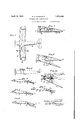
- Figure 1 is a plan view of a biplane type Russ'ua) of air plane incorporating my invention, certain portions of the airplane notnecessary for the purpose of illustrating this invention being omitted
- Fig. 2 is a side view thereof showing-by dotted lines the shifted positions of the aileron and of portions of the wing
- Fig. 3 isan enlarged sectional view through the Wing on the line 33 of Fig. 1, showing the lower surface at the rear portion of the wing
- Fig. 4 is a similar View thereof but showing the pivoted portion shifted dorwnwardlyto its extreme position; Figs.
- FIG. 5 and 6 are, respectively, enlarged fragmentary Views of the wing shown in Figs.
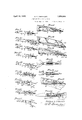
- Figs. 7 and- 8 are sectional 7 views similar to Figs. 3 and 4 but showing modified-means for shifting the pivoted wing surface
- Fig. 9 is afsectional view of a wing structure embodying my invention in a. slightly modified form
- Fig. 10 is a sectional view thereof showing the pivoted wing section shifted downwardly and airfoil sections pivoted to the trailing edges of the rigid and shiftable portion
- Fig. 11 is another view thereof showing the pivoted airfoil sections shifted backwardly for increasing the chord of the wing
- Figs. 10 is a sectional view thereof showing the pivoted wing section shifted downwardly and airfoil sections pivoted to the trailing edges of the rigid and shiftable portion
- Fig. 11 is another view thereof showing the pivoted airfoil sections shifted backwardly for increasing the chord of the wing
- Fig. 12 is, respectively, enlarged sectional views of the rear portions of the wings shown in Figs. 9,10 and 11;
- Fig. 15 is an enlarged fragmentary view of yieldable link means for shifting the above mentioned airfoil section;
- Fig. 16 is a side view of the link means partly in section;
- Figs. 17 and 18 are other sectional views of wings showing other slightly modified forms of construction and showing the closed and open positions for the folded and unfolded positions;
- Fig. 19 is an enlarged fragmentary sectional view of the rear portion of the wing in the position shown in Fig. 18;
- Fig. 20 is a sectional 'view of a wing showing another slightly modified form of construction;
- Fig. 21 is a sectional view of a structure similar to that shown in Fig. 20,
- Fig. 25 is a fragmentary sectional view of another modification of my invention.
- Fig. 1 of the drawings the pivoted portions of the wings, designated A, are positioned intermediate the ends of the wings and extend between the ailerons B and the fuselage C, the ailerons in this instance being at the extreme ends of the wings and backwardly from the front spars of the wings. It is to be understood, ho'wever, that the specific location of the pivoted portions of t e wings may be varied as desired and is not confined to the specific location illustrated.
- the wing is formed or reinforced by the usual spars 1 and 2 extending longitudinally of the win near the entering edge and about midway etween the vspar 1 and the trailin edge, or somewhat closer to the trailing e ge than to the former. These spars are reinforced and the shape of the wing and camber formed by the ribs 3.
- ribs may be covered by any suitable fabric or other coverin 4 which extends from the lower side of t e rear spar 2, around the under side of the wing, aroundthe entering edge and over the upper surface of the wing to the trailin edge 5 of the upper surface
- the opening etween the rear spar 2 and the trailing edge 5 of the upper surface of, the wing is normally enclosed by a shiftable win surface or section 6 which is constructed similar to other airfoils except that it is enclosed at one side only, the other or inner side, designated 6a, having the reinforcing ribs and other members.
- This shiftable win section 6 is hinged at its forward edge pre erably to the spar 2 or any other suitable portion of the rigid portion of the wing, as the upper portion may be called.
- the lower or pivoted wing section 6 may be shifted relative to the rigid upper portion by toggle joint members 7 pivotally connected together and to the rigid wing section and the shiftable wing-section.
- toggle joint members 7 may be contracted, as shown in Fig. 5, by a crank arm 8 pivotally connected to the toggle joint members by a link 9, the crank member 8 being mounted on the rigid wing section and extending toward and preferably into the fuselage so that the same may be operated readily.
- the wing When the lower wing section is shifted to its upper or folded position, as shown in Fig. 5, the wing functions the same as in the ordinary wing; but when the same is shifted downwardly to the position shown in Fig. 6, the angle of incidence is increased materially increasing the lift of the wing and also increasing the head resistance, therefore, facilitating the landing of airplanes. The takeoff distance on the ground is also decreased by the increased angle of incidence.
- the rigid and shiftable wing or airfoil sections shown in Figs. 7 and 8, are similar to those previously described,.but the shiftablewing sections are shifted downwardly by torque rods 10 at the pivotal axis of the pivoted wing section.
- This torque rod extends through the wing and preferably into the fuselage where the same may be rotated by a suitable lever 11.
- the rigid and shiftable wing sections and the means for operating the same, as shown in Figs. 9 to 14, inclusive, are substantially the same as those described in Figs. 3 to 6.
- the air oil section 21 is pivoted at one edge to near the trailing edge of the rigid portion of the wing and assumes substantially the same curvature.
- the section 22 is pivoted at one edge to near the trailing edge of the shiftable wing section 6.
- These sections 21 and 22 are pivotally connected at their opposite edges to each other, substantially as shown in Figs. 13 and 14.
- These airfoil sections 21 and 22 are adapted to enclose the gap or open space between the trailing edges of the rigid portion of the wing and the shiftable portion when the latter is shifted downwardly to a greater angle of incidence.
- the sections 21 and 22 are folded inwardly between the rear portion of the rigid Wing section and the shiftable portion, as shown best in Fig. 12.
- Such shift consists of a pair of slidably connectedmembers 23a and 236 the latter of which is provided with a transverse pin 23@ slidable in longitudinal slots in the member 23a, and springs 23c and 23d positioned within the link 2311 and in engagement with the opposite side of the pin 23c.
- the airfoil sections 24 and 25 When these airfoil sections 24 and 25 are shifted outwardly by the link 26 which is connected to the toggle members 7, the airfoil sections 24 and 25 also enclosethe space at the trailing edges of the rigid and shiftable ging sections, as shown by dotted lines in he structure shown in Figs. 20 to 24, inelusive, are slightly different in that the rear spar 2 is decreased in height and a third s ar, designated 27, ispositioned between t e forward and 'rear spar.
- the shiftable .wing section 6 in this instance is pivotally connected at its forward edge to the lower portion of the intermediate spar 27, so that a wider shiftable section '6 may be used.
- Fig. 20 the operation or shifting of theshiftable wing section 6 is effected by toggle means, as described above.
- the section 6 is shifted by cables 28 and 29 extending, respectively, around sheaves 30 and 31 mounted on the under side of the rigid wing section, and at the inner side thereof on or adjacent the rear spar 2. From the sheave 31 the cable extends preferably around another sheave 32 and then toward the fuselage of the airplane.
- the toggle means consisting of links 33 and 34, is ata right angle to that previously described and is actuated by cables 35 and 36, as shown best in Fig. 24.
- the wings may serve as ailerons when separately operated which may be effected by the usualcontrol stick.
- Fig.25 shows the structure similar to that shown in Figs. 3 to 6 in which the rear portion of the lower surface of the wing may be tilted downwardly at an angle, but also shows the rear portion of the upper surface of the wing pivoted at its forward edge and adapted to be-tilted upwardly.
- Both of these airfoil surfaces designated respectively 6 and 41 may be variously shifted to their tilted positions by any suitable means.
- the airfoil surfaces are pivoted at their forward edges to the rear side of the rear spar. To this spar are also secured the frames or brackets 42 which extend backwardly.
- brackets are provided with longitudinal guide portions 42a and 42b in which are reciprocally mounted respectively one end oflinks 43 and 44 which links are pivotally connected at their opposite end to the inner side of the shiftable airfoil surfaces 6 and 41.
- links 43 and 44 are drawn inwardly along the guide portions, the airfoil surfaces collapse inwardly assuming the powhich they may be controlled as desired.
- the airfoil surfaces 6 and 41 may be separately controlled so that only the airfoil surfaces 6 may be shifted downwardly when taking off, or both may be shifted outwardly when landing, the out wardly shifting of both surfaces increasing not only the lift but markedly increasing the head resistance.
- a rigid forward and upper portion a shiftable surface pivoted at its forward edge at the lower and rear portion of the rigid forwardand upper portion, the trailing edges of both being adapted to be separated when said shiftable surface is lowered about its pivotal axis, and narrow airfoil surfaces, each pivoted at one edge to one edge ofeach of the former and also pivoted together at their opposite ed es, said narrow airfoil surfaces enclosing t e space between the trailing edges of the ri 'd upper and forward portion and of the s iftable surface, and also forming a substantial streamline effect for the airfoil when the shiftable surface is lowered, the narrow airfoil surfaces being adapted to be folded backwardly for increasing chord of the airfoil.
- a rigid forward and upper portion a shiftable surface pivoted at its forward edge at the lower and rear portions of the rigid forward and upper portion, the trailin edges of both bein adapted to be separate when said shiftabfia surface is lowered about its pivotal axis, and narrow airfoil surfaces, each pivoted at one edge to one edge of each of the former and also pivoted to ether at their opposite edges, said narrow airfoil surfaces enclosing the space between the trailing edges of the rigid upper and forward portion of the shiftable surface, and also forming a substantial streamline effect for the airfoil when the shiftable surface is lowered, the narrow airfoil surfaces being adapted to be folded backwardly for increasing the chord of the airfoil, said narrow airfoil surfaces when folded backwardly forming substantial continuations of theupper surface and lower surface of the airfoil.
- a rigid up r portion pivote at its forward edge to the under side of the rigid upper portion and adapted to be shifted to a greater angle of incidence and separated from the u per portion, and narrow airfoil surfaces inged to the trailing edges of each of the rigid upper portion and the shiftable lower ortion, the narrow airfoil surfaces being a so hinged to ether at their free edges and to be shifted baclrwardly from such trailing edges forming substantial streamlined effect for the rigid upper portion and shiftable lower portion when the same are separated at their trailing edges.
- a rigid upper portion a shiftable lower portion pivoted at its forward edge to the under side of the rigid upper portion and adapted to be shifted to a greater angle of incidence and separated from the upper portion, and narrow airfoil surfaces hinged to the trailing edges of each of the rigid upper portion and the shiftable lower portion, the narrow airfoil surfaces being also hinged together at their free edges and to be shifted backwardly from such trailing edges forming substantial streamlined effect for the rigid upper portion and shiftable lower portion when the same are separated at their trailing edges, said narrowairfoil surfaces being foldable between the rigid upper portion and the shiftable lower portion when the shiftable lower portion is in its normal position of flight with respect to the rigid upper portion.
- a rigid upper portion a shiftable lower ortion pivoted at its forward edge to the un er side of the rigid upper portion and adapted to be shifted to a greater angle of incidence and separated from the upper portion, and narrow airfoll surfaces hinged to the trailing edges of each of the rigid upper portion and the shiftable lower portion, the narrow airfoil surfaces being also hinged together at their free edges and'to be shifted backwardly from such trailing edges forming substantial streamlined effect for the rigid upper portion and shiftable lower portion, when the same are separated at their trailing edges, said narrow airfoil surfaces being foldable between the rigid upper ortion and the shiftable lower portion w en the shiftable lower portion is in its normal position of flight with respect to the rigid upper portion, said narrow airfoil surfaces being also foldable outwardly for increasing the chord of the airfoil, said narrow airfoil surfaces forming substantial continua-tions of the exposed surfaces of the rigid upper portion and the shiftable lower portion.
- anairplane wing structure a framework, a permanent covering over the upper side and the forward portion of the lower side, a shiftable wing surface hinged at its forward edge at the lower portion jof the framework and at the rear edge of the covering for the forward portion of the lower side of the framework, means for raising and lowering the pivoted" wing surface for varying the angle of incidence of the rear portion of the win structure, and narrow airfoil surfaces, eac hinged at one edge to the trailing edges of each of the framework and the lower wing surface, said narrow airfoil surfaces being hinged together at their opposite edges, said narrow airfoil surfaces being adapted to enclose the space between the framework and the pivoted wing surface when the latter is lowered about its pivotal axis, the narrow airfoil surfaces being adapted to be folded between the framework and the pivoted wing surface when the latter is shifted to its normal upper position, and also adapted'to be folded backwardly for increasing the chord of the wing.
- an airplane wing member having a cut-out portion, at its end and extending from immediately behind its entering edge to its trailing edge, an aileron pivotally mounted at its forward edge immediately behind said entering edge andextending in said cut-out portion to the trailing edge of the wing member, and an airfoil surface pivotally mounted at its forward edge at the lower side and intermediate the entering and trailing edges of the wing member and inwardly from the aileron, said 5 airfoil surface being adapted to conform tothe surface of the underside of the Wing member and adapted also to be shifted at an angle thereto from the pivotal axis of the airfoil surface.
Landscapes
- Engineering & Computer Science (AREA)
- Mechanical Engineering (AREA)
- Aviation & Aerospace Engineering (AREA)
- Toys (AREA)
Description
April 19, 1932. G. E. BARNHART 1,354,444
AIRPLANE WING CONSTRUCTION Filed Sept. 3, 1929 2 Sheets-Sheet l /.V MENTOR GL'OHGE 5 BARN/{AFT 42$ @UWWLM/ A TTORNEY p i 1932- G. E. BARNHART 1,854,444
AIRPLANE WING CONSTRUCTION Filed Sept. 3, 1929 2 Sheets-Sheet 2 INVENTOR GZORGE E. BflR/VHA F7 A TTORNE Y Patented Apr. 19, 1932 UNITED STATES PATENT OFFICE Applieationfiled September -3, 1929. Serial No. 389,932.
My present inventionrelates to airfoil construction for airplanes, and particularly to wing construction of airplanes.
The objects of this invention are: first, to provide a wing or other airfoil whereby the angle of incidence or angle of attack of the wing or other airfoil may be easily and quickly changed so that, when desired, the lift of the wing of other airfoil may be increased to a maximum substantially instantaneously; second, to provide a wing or other airfoil structure for airplanes whereby'the angle of incidence of a portion of the wing or other airfoil may be increased quickly-and easily, and to provide such a wing structure in which there is no sacrifice in strength of the wing; third, to provide a wing or other airfoil structure whereby a portion of the wing or airfoil is shifted to a greater angle of incidence thereby increasing the head resistance and also the lift, thus providing means to facilitate the landing of airplanes; fourth, to provide a connected by other airfoils and thereby sub-.
wing or other airfoil structure in which the trailing edges of angularly separated portions of the wing or other airfoil structure are stantially streamlining the gap or open space between the separated portions, and the trailing edges thereof; fifth, to provide a wing structure in which the chord of the wing may be increased easily by pivoted portions of the wing, which pivoted portions may be folded forwardly 'between a rigid upper portion and a shiftable lower portion of the wing, and when so folded forwardly the same are concealed and the wing assumes a normally shaped wing of shorter chord; sixth, to provide novel means for shifting the variouswing or airfoil surfaces; and, seventh, to provide a novel and simple and economical wing stabilizer, or control or other airfoil surface for airplanes, and one which will not readily deteriorate or get out of order.
With these and other objects in view as will appear hereinafter, my invention consists of certain novel features of construction, combination and arrangement of parts and portions as will be hereinafter described in detail and particularly set forth in the appended claims, reference being had to the accompan ing drawings and to the characters of re erence thereon which form a part of this application in which:
Figure 1 is a plan view of a biplane type Russ'ua) of air plane incorporating my invention, certain portions of the airplane notnecessary for the purpose of illustrating this invention being omitted Fig. 2 is a side view thereof showing-by dotted lines the shifted positions of the aileron and of portions of the wing; Fig. 3 isan enlarged sectional view through the Wing on the line 33 of Fig. 1, showing the lower surface at the rear portion of the wing; Fig. 4 is a similar View thereof but showing the pivoted portion shifted dorwnwardlyto its extreme position; Figs.
5 and 6 are, respectively, enlarged fragmentary Views of the wing shown in Figs.
3 and 4 to facilitate the illustration of the mounting and operation of the pivoted portions of-the wing; Figs. 7 and- 8 are sectional 7 views similar to Figs. 3 and 4 but showing modified-means for shifting the pivoted wing surface; Fig. 9 is afsectional view of a wing structure embodying my invention in a. slightly modified form; Fig. 10 is a sectional view thereof showing the pivoted wing section shifted downwardly and airfoil sections pivoted to the trailing edges of the rigid and shiftable portion; Fig. 11 is another view thereof showing the pivoted airfoil sections shifted backwardly for increasing the chord of the wing; Figs. 12, 13 and 14 are, respectively, enlarged sectional views of the rear portions of the wings shown in Figs. 9,10 and 11; Fig. 15 is an enlarged fragmentary view of yieldable link means for shifting the above mentioned airfoil section; Fig. 16 is a side view of the link means partly in section; Figs. 17 and 18 are other sectional views of wings showing other slightly modified forms of construction and showing the closed and open positions for the folded and unfolded positions; Fig. 19 is an enlarged fragmentary sectional view of the rear portion of the wing in the position shown in Fig. 18; Fig. 20 is a sectional 'view of a wing showing another slightly modified form of construction; Fig. 21 is a sectional view of a structure similar to that shown in Fig. 20,
i but embodying a different means of operaline with respect to the wing and also showing the pivoted portionin its upwardly shifted position; and Fig. 25 is a fragmentary sectional view of another modification of my invention.
Like characters of reference refer to similar parts and portions throughout the several views of the drawings.
In Fig. 1 of the drawings the pivoted portions of the wings, designated A, are positioned intermediate the ends of the wings and extend between the ailerons B and the fuselage C, the ailerons in this instance being at the extreme ends of the wings and backwardly from the front spars of the wings. It is to be understood, ho'wever, that the specific location of the pivoted portions of t e wings may be varied as desired and is not confined to the specific location illustrated.
In the structures illustrated in Figs. 3 to 19, inclusive, the wing is formed or reinforced by the usual spars 1 and 2 extending longitudinally of the win near the entering edge and about midway etween the vspar 1 and the trailin edge, or somewhat closer to the trailing e ge than to the former. These spars are reinforced and the shape of the wing and camber formed by the ribs 3. These ribs may be covered by any suitable fabric or other coverin 4 which extends from the lower side of t e rear spar 2, around the under side of the wing, aroundthe entering edge and over the upper surface of the wing to the trailin edge 5 of the upper surface The opening etween the rear spar 2 and the trailing edge 5 of the upper surface of, the wing is normally enclosed by a shiftable win surface or section 6 which is constructed similar to other airfoils except that it is enclosed at one side only, the other or inner side, designated 6a, having the reinforcing ribs and other members. This shiftable win section 6 is hinged at its forward edge pre erably to the spar 2 or any other suitable portion of the rigid portion of the wing, as the upper portion may be called.
As shown best in Figs. 5 and 6, the lower or pivoted wing section 6 may be shifted relative to the rigid upper portion by toggle joint members 7 pivotally connected together and to the rigid wing section and the shiftable wing-section. These toggle joint members 7 may be contracted, as shown in Fig. 5, by a crank arm 8 pivotally connected to the toggle joint members by a link 9, the crank member 8 being mounted on the rigid wing section and extending toward and preferably into the fuselage so that the same may be operated readily.
When the lower wing section is shifted to its upper or folded position, as shown in Fig. 5, the wing functions the same as in the ordinary wing; but when the same is shifted downwardly to the position shown in Fig. 6, the angle of incidence is increased materially increasing the lift of the wing and also increasing the head resistance, therefore, facilitating the landing of airplanes. The takeoff distance on the ground is also decreased by the increased angle of incidence.
The rigid and shiftable wing or airfoil sections, shown in Figs. 7 and 8, are similar to those previously described,.but the shiftablewing sections are shifted downwardly by torque rods 10 at the pivotal axis of the pivoted wing section. This torque rod extends through the wing and preferably into the fuselage where the same may be rotated by a suitable lever 11.
The rigid and shiftable wing sections and the means for operating the same, as shown in Figs. 9 to 14, inclusive, are substantially the same as those described in Figs. 3 to 6. In the structure shown in Figs. 9 to 14, however, I have provided additional surfaces 21 and 22 which are referred to as airfoil sections. These sections are relatively narrow and extend the full len th of the shiftable wing section 6. The air oil section 21 is pivoted at one edge to near the trailing edge of the rigid portion of the wing and assumes substantially the same curvature. The section 22 is pivoted at one edge to near the trailing edge of the shiftable wing section 6. These sections 21 and 22 are pivotally connected at their opposite edges to each other, substantially as shown in Figs. 13 and 14. These airfoil sections 21 and 22 are adapted to enclose the gap or open space between the trailing edges of the rigid portion of the wing and the shiftable portion when the latter is shifted downwardly to a greater angle of incidence. When the ordinary wing chord and section is desired, the sections 21 and 22 are folded inwardly between the rear portion of the rigid Wing section and the shiftable portion, as shown best in Fig. 12. Such shiftconsists of a pair of slidably connectedmembers 23a and 236 the latter of which is provided with a transverse pin 23@ slidable in longitudinal slots in the member 23a, and springs 23c and 23d positioned within the link 2311 and in engagement with the opposite side of the pin 23c.
When the sections 21 and 22 are shifted backwardly to the extreme position, as shown in Fig. 14, the same form extensions of the upper or rigid wing section and the shiftable wing section and'conformsubstantially with the curvature of the exterior surfaces thereof, extending the width or chord and there fore the lifting effect of the wing. 4
The structure, shown in Figs. 17, 18 and 19, is similar to that just described inperforming the function of closing the gap or space between the shiftable lower win section and the rigid upper wing section w en the former is shifted downwardly. In the structure shown in Figs. 17, 18 and 19, the section '24,
which is pivoted to the rigid portion of the wing, is shaped on an obtuse angle and forms, with the portion pivoted to the rigid wing section, an airfoil surface at the extreme ,trailingedge of the lower portion of thewing, and a continuation of the lower surface of the shiftable or pivoted wing section 6. To the other edge of the airfoil section 24 is pivoted another airfoil section 25 which is in turn pivoted at its opposite edge to the free edge of the pivoted wing section 6.
When these airfoil sections 24 and 25 are shifted outwardly by the link 26 which is connected to the toggle members 7, the airfoil sections 24 and 25 also enclosethe space at the trailing edges of the rigid and shiftable ging sections, as shown by dotted lines in he structure shown in Figs. 20 to 24, inelusive, are slightly different in that the rear spar 2 is decreased in height and a third s ar, designated 27, ispositioned between t e forward and 'rear spar. The shiftable .wing section 6 in this instance is pivotally connected at its forward edge to the lower portion of the intermediate spar 27, so that a wider shiftable section '6 may be used. In
Fig. 20 the operation or shifting of theshiftable wing section 6 is effected by toggle means, as described above. In Figs. 21 and 22 the section 6 is shifted by cables 28 and 29 extending, respectively, around sheaves 30 and 31 mounted on the under side of the rigid wing section, and at the inner side thereof on or adjacent the rear spar 2. From the sheave 31 the cable extends preferably around another sheave 32 and then toward the fuselage of the airplane. In Figs. 23 and 24 the toggle means, consisting of links 33 and 34, is ata right angle to that previously described and is actuated by cables 35 and 36, as shown best in Fig. 24. It will be noted that instead of employing .of the wings may serve as ailerons when separately operated which may be effected by the usualcontrol stick.
Fig.25 shows the structure similar to that shown in Figs. 3 to 6 in which the rear portion of the lower surface of the wing may be tilted downwardly at an angle, but also shows the rear portion of the upper surface of the wing pivoted at its forward edge and adapted to be-tilted upwardly. Both of these airfoil surfaces designated respectively 6 and 41 may be variously shifted to their tilted positions by any suitable means. In the illustrations the airfoil surfaces are pivoted at their forward edges to the rear side of the rear spar. To this spar are also secured the frames or brackets 42 which extend backwardly. These brackets are provided with longitudinal guide portions 42a and 42b in which are reciprocally mounted respectively one end oflinks 43 and 44 which links are pivotally connected at their opposite end to the inner side of the shiftable airfoil surfaces 6 and 41. As the ends of the links 43 and 44 are drawn inwardly along the guide portions, the airfoil surfaces collapse inwardly assuming the powhich they may be controlled as desired. It
will be here noted that the airfoil surfaces 6 and 41 may be separately controlled so that only the airfoil surfaces 6 may be shifted downwardly when taking off, or both may be shifted outwardly when landing, the out wardly shifting of both surfaces increasing not only the lift but markedly increasing the head resistance.
Though I have shown and described a particular construction, combination and arrangement of parts and portions, and certain modifications thereof, I do not wish to be limited to this particular construction,- com bination and arrangement, nor to themodifications, but desire to include in the scope of my invention the construction, combination and arrangement substantially as set forth in the appended claims.
Having thus described my invention, what I claim as new and desire to secure by Letters Patent is:
1. In an airfoil of the class described, a rigid forward and upper portion, a shiftable surface pivoted at its forward edge at the lower and rear portion of the rigid forwardand upper portion, the trailing edges of both being adapted to be separated when said shiftable surface is lowered about its pivotal axis, and narrow airfoil surfaces, each pivoted at one edge to one edge ofeach of the former and also pivoted together at their opposite ed es, said narrow airfoil surfaces enclosing t e space between the trailing edges of the ri 'd upper and forward portion and of the s iftable surface, and also forming a substantial streamline effect for the airfoil when the shiftable surface is lowered, the narrow airfoil surfaces being adapted to be folded backwardly for increasing chord of the airfoil.
2. In an airfoil of the class described, a rigid forward and upper portion, a shiftable surface pivoted at its forward edge at the lower and rear portions of the rigid forward and upper portion, the trailin edges of both bein adapted to be separate when said shiftabfia surface is lowered about its pivotal axis, and narrow airfoil surfaces, each pivoted at one edge to one edge of each of the former and also pivoted to ether at their opposite edges, said narrow airfoil surfaces enclosing the space between the trailing edges of the rigid upper and forward portion of the shiftable surface, and also forming a substantial streamline effect for the airfoil when the shiftable surface is lowered, the narrow airfoil surfaces being adapted to be folded backwardly for increasing the chord of the airfoil, said narrow airfoil surfaces when folded backwardly forming substantial continuations of theupper surface and lower surface of the airfoil. v
' 3. In an airfoil structure, a rigid up r portion, a shiftable lower portion pivote at its forward edge to the under side of the rigid upper portion and adapted to be shifted to a greater angle of incidence and separated from the u per portion, and narrow airfoil surfaces inged to the trailing edges of each of the rigid upper portion and the shiftable lower ortion, the narrow airfoil surfaces being a so hinged to ether at their free edges and to be shifted baclrwardly from such trailing edges forming substantial streamlined effect for the rigid upper portion and shiftable lower portion when the same are separated at their trailing edges.
4. In an airfoil structure, a rigid upper portion, a shiftable lower portion pivoted at its forward edge to the under side of the rigid upper portion and adapted to be shifted to a greater angle of incidence and separated from the upper portion, and narrow airfoil surfaces hinged to the trailing edges of each of the rigid upper portion and the shiftable lower portion, the narrow airfoil surfaces being also hinged together at their free edges and to be shifted backwardly from such trailing edges forming substantial streamlined effect for the rigid upper portion and shiftable lower portion when the same are separated at their trailing edges, said narrowairfoil surfaces being foldable between the rigid upper portion and the shiftable lower portion when the shiftable lower portion is in its normal position of flight with respect to the rigid upper portion.
5. In an airfoil structure, a rigid upper portion, a shiftable lower ortion pivoted at its forward edge to the un er side of the rigid upper portion and adapted to be shifted to a greater angle of incidence and separated from the upper portion, and narrow airfoll surfaces hinged to the trailing edges of each of the rigid upper portion and the shiftable lower portion, the narrow airfoil surfaces being also hinged together at their free edges and'to be shifted backwardly from such trailing edges forming substantial streamlined effect for the rigid upper portion and shiftable lower portion, when the same are separated at their trailing edges, said narrow airfoil surfaces being foldable between the rigid upper ortion and the shiftable lower portion w en the shiftable lower portion is in its normal position of flight with respect to the rigid upper portion, said narrow airfoil surfaces being also foldable outwardly for increasing the chord of the airfoil, said narrow airfoil surfaces forming substantial continua-tions of the exposed surfaces of the rigid upper portion and the shiftable lower portion.
6. In anairplane wing structure, a framework, a permanent covering over the upper side and the forward portion of the lower side, a shiftable wing surface hinged at its forward edge at the lower portion jof the framework and at the rear edge of the covering for the forward portion of the lower side of the framework, means for raising and lowering the pivoted" wing surface for varying the angle of incidence of the rear portion of the win structure, and narrow airfoil surfaces, eac hinged at one edge to the trailing edges of each of the framework and the lower wing surface, said narrow airfoil surfaces being hinged together at their opposite edges, said narrow airfoil surfaces being adapted to enclose the space between the framework and the pivoted wing surface when the latter is lowered about its pivotal axis, the narrow airfoil surfaces being adapted to be folded between the framework and the pivoted wing surface when the latter is shifted to its normal upper position, and also adapted'to be folded backwardly for increasing the chord of the wing.
7. In a means of the class described, an airplane wing member having a cut-out portion, at its end and extending from immediately behind its entering edge to its trailing edge, an aileron pivotally mounted at its forward edge immediately behind said entering edge andextending in said cut-out portion to the trailing edge of the wing member, and an airfoil surface pivotally mounted at its forward edge at the lower side and intermediate the entering and trailing edges of the wing member and inwardly from the aileron, said 5 airfoil surface being adapted to conform tothe surface of the underside of the Wing member and adapted also to be shifted at an angle thereto from the pivotal axis of the airfoil surface.
In testimony. whereof, I have hereunto set my hand at Pasadena, California, this 22 day of August, 1929.
, GEORGE E. BARNHART.
Priority Applications (1)
| Application Number | Priority Date | Filing Date | Title |
|---|---|---|---|
| US389932A US1854444A (en) | 1929-09-03 | 1929-09-03 | Airplane wing construction |
Applications Claiming Priority (1)
| Application Number | Priority Date | Filing Date | Title |
|---|---|---|---|
| US389932A US1854444A (en) | 1929-09-03 | 1929-09-03 | Airplane wing construction |
Publications (1)
| Publication Number | Publication Date |
|---|---|
| US1854444A true US1854444A (en) | 1932-04-19 |
Family
ID=23540369
Family Applications (1)
| Application Number | Title | Priority Date | Filing Date |
|---|---|---|---|
| US389932A Expired - Lifetime US1854444A (en) | 1929-09-03 | 1929-09-03 | Airplane wing construction |
Country Status (1)
| Country | Link |
|---|---|
| US (1) | US1854444A (en) |
Cited By (7)
| Publication number | Priority date | Publication date | Assignee | Title |
|---|---|---|---|---|
| US2426785A (en) * | 1943-07-03 | 1947-09-02 | Donald J Naumann | Variable airfoil |
| US2434341A (en) * | 1943-09-02 | 1948-01-13 | Electrolux Corp | Wing flap actuating mechanism |
| US3454239A (en) * | 1967-04-05 | 1969-07-08 | Peter J Frey | Counterflow jet flap |
| US3986688A (en) * | 1975-06-16 | 1976-10-19 | The United States Of America As Represented By The Secretary Of The Air Force | Variable effectiveness stabilizing/controlling surface |
| US4427169A (en) | 1982-06-08 | 1984-01-24 | Boeing Commercial Airplane Company | Variable camber flap end seal |
| US5655737A (en) * | 1992-11-24 | 1997-08-12 | Northrop Grumman Corporation | Split rudder control system aerodynamically configured to facilitate closure |
| US6382562B1 (en) * | 1999-11-10 | 2002-05-07 | The Boeing Company | AFT egress and control device for an aircraft |
-
1929
- 1929-09-03 US US389932A patent/US1854444A/en not_active Expired - Lifetime
Cited By (7)
| Publication number | Priority date | Publication date | Assignee | Title |
|---|---|---|---|---|
| US2426785A (en) * | 1943-07-03 | 1947-09-02 | Donald J Naumann | Variable airfoil |
| US2434341A (en) * | 1943-09-02 | 1948-01-13 | Electrolux Corp | Wing flap actuating mechanism |
| US3454239A (en) * | 1967-04-05 | 1969-07-08 | Peter J Frey | Counterflow jet flap |
| US3986688A (en) * | 1975-06-16 | 1976-10-19 | The United States Of America As Represented By The Secretary Of The Air Force | Variable effectiveness stabilizing/controlling surface |
| US4427169A (en) | 1982-06-08 | 1984-01-24 | Boeing Commercial Airplane Company | Variable camber flap end seal |
| US5655737A (en) * | 1992-11-24 | 1997-08-12 | Northrop Grumman Corporation | Split rudder control system aerodynamically configured to facilitate closure |
| US6382562B1 (en) * | 1999-11-10 | 2002-05-07 | The Boeing Company | AFT egress and control device for an aircraft |
Similar Documents
| Publication | Publication Date | Title |
|---|---|---|
| US3941334A (en) | Variable camber airfoil | |
| US4053124A (en) | Variable camber airfoil | |
| US2744698A (en) | High speed aircraft wing and tail surfaces having variable sweepback | |
| US2573271A (en) | Roadable aircraft | |
| US2941752A (en) | Aircraft with retractable auxiliary airfoil | |
| US2822995A (en) | Adjustable wing aircraft | |
| US2405726A (en) | Airplane wing construction | |
| US2210642A (en) | Aircraft | |
| US2271226A (en) | Airplane | |
| US1790309A (en) | Aeroplane wing | |
| US1710670A (en) | Tttbix of said leonard w | |
| US1854444A (en) | Airplane wing construction | |
| US2349858A (en) | Adjustable airfoil | |
| US1893065A (en) | Aircraft and control thereof | |
| US2249729A (en) | Airplane wing | |
| US2222997A (en) | Control means for airplanes | |
| US1710672A (en) | Aeroplane control | |
| USRE20075E (en) | Airplane wing constructhw | |
| CN112722241A (en) | Telescopic belly flap | |
| US2570534A (en) | Aerodynamic trim means | |
| US2152835A (en) | Aircraft | |
| US2740597A (en) | Airfoil | |
| US2158686A (en) | Airfoil construction | |
| US1856219A (en) | Aeroplane | |
| CN111284683A (en) | Aircraft wing assembly |