US1854442A - Shock absorber - Google Patents
Shock absorber Download PDFInfo
- Publication number
- US1854442A US1854442A US244103A US24410328A US1854442A US 1854442 A US1854442 A US 1854442A US 244103 A US244103 A US 244103A US 24410328 A US24410328 A US 24410328A US 1854442 A US1854442 A US 1854442A
- Authority
- US
- United States
- Prior art keywords
- spring
- shock absorber
- resisting
- lever
- plate
- Prior art date
- Legal status (The legal status is an assumption and is not a legal conclusion. Google has not performed a legal analysis and makes no representation as to the accuracy of the status listed.)
- Expired - Lifetime
Links
Images
Classifications
-
- F—MECHANICAL ENGINEERING; LIGHTING; HEATING; WEAPONS; BLASTING
- F16—ENGINEERING ELEMENTS AND UNITS; GENERAL MEASURES FOR PRODUCING AND MAINTAINING EFFECTIVE FUNCTIONING OF MACHINES OR INSTALLATIONS; THERMAL INSULATION IN GENERAL
- F16F—SPRINGS; SHOCK-ABSORBERS; MEANS FOR DAMPING VIBRATION
- F16F1/00—Springs
- F16F1/02—Springs made of steel or other material having low internal friction; Wound, torsion, leaf, cup, ring or the like springs, the material of the spring not being relevant
- F16F1/18—Leaf springs
- F16F1/22—Leaf springs with means for modifying the spring characteristic
Definitions
- This invention relates generally to shock absorbers for vehicle springs and the like and has particular reference to a new and improved auxiliary rebound control for vehicle springs which shall be simple in construction and readily adaptable for attachment to' existing types of leaf springs.
- One of the objects of my invention is to provide a readily attacliable shock absorber which shall permit the flexing of a leaf spring in one direction but which shall resist the bending action of such spring when it is flex-ed in the opposite direction.
- Another object of my invention is to provide a shock absorber which comprises a single resisting member7 a comparatively short securing shackle and adjustable means for varying the resistance of the resisting member.
- a further object of my invention is found in the provision of an elongated resisting member adapted to be attached to an elliptical spring and constituting a pair of lever arms arranged to resist the flexing of the spring ends in one direction.
- a still further object of my invention is found in the embodiment of such elongated resisting member extending substantially the entire length of the elliptical spring and provided with means near its ends for adjustably varying the resistance of such member.
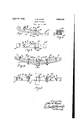
- c- Fig. l is a side elevation of a rebound control or shock absorber embodying my invention as applied near one end of an elliptiv'cal spring7 the spring being only partly shown in this illustration.
- Fig. 2 is a cross section taken on line 2-2 of Fig. l.
- Fig. 3 is a plan view of the shock absorber shown in Fig. l.
- Fig. l is a side elevation of a modilied form of my invention wherein the resisting member for both ends of the elliptical spring constitutes a single plate having supporting means and adjustable means for varying its resistance; the resisting plate itself being partly in section to show the supportingv means which limit its longitudinal and transverse movement but permit a vertical movement of its end portions.
- Fig. 5 is a section plan view taken on line 5 ⁇ 5 of Fig. 4l.
- rlhe resisting member 11 comprises a flat bar or plate of suitable thickness and preferably of a width equal to the width of the leaves 10A of the spring 10.
- the resisting member is formed with the inner end 11A bent right-angularly for engagement with the upper leaf 10A.
- the other end of the member 11 is provided with a set screw 12 and a lock nut 13.
- the lower end of the set screw l2 also engages upon the upper leaf spring 10A.
- a shackle 14y is provided for retaining the resisting member 11 against longitudinal and transverse movement and comprises a U-shaped bar 14A and bolt 14B.
- the portion of the member ll beneath the bolt 14B is bent as at 11B to form a cross channel for the bolt 14B to prevent longitudi* nal movement of the member 1l relatively to the shackle 14E.
- thefelliptical spring 10 is shown in full elevation in Fig. 4, and the resisting member 15 in this case is elongated or extended under the U-bolts 17 over substantially the iulllength of the spring 10.
- the member 15 comprises a flat bar having a slight arcuate formation which is held in spaced relation to the spring 10 by means of the illerplate 10B and set screws 12.
- Suitable U-bolt shackles 16 are provided which produce comparatively short resisting armsflAat the ends of the member 15 and which prevent longitudinal and transverse movement of the member 15 relatively to the spring 10.
- the upper surface of the member 15, on. both sides of the horizontal portion of the U-bolt 16', is deformed or slightly raised by punching operation to form the raised portions 15B.
- a shock absorber comprising a short stifispringmetal plate contacting one free end portion of a vehicle spring at a position longitudinally spaced from the anchored intermediate portion of the latter, one end of said plate being bent to contact with a leai" of the spring, a tensioning screw passing through the other end of said plate for adjusting the tension thereof, and a clamp to extendk jointly around said free'end portion of the spring and an intermediate portion of said plate, said clamp embodying a transverse portion upon which said intermediate portion of said plate rests, said plate having a transverse groove rockably receiving said JOHN W. BAIRD.
Landscapes
- Engineering & Computer Science (AREA)
- General Engineering & Computer Science (AREA)
- Mechanical Engineering (AREA)
- Vehicle Body Suspensions (AREA)
Description
April 19, 1932. J, w, BAIRD` 1,854,442
SHOCK ABSORBER Filed Jan. 5, 1928 A /O f /-l l Y y z 1.49 I
l ,IMU J Y .lfmllff WL lu [rivera/W* Patented Apr. 19, 1932 TAT JOI-IN W. BAIRD, OF GLEN ELLYN, ILLINOIS SHOCK ABSORBER Application filed. January 3, 1928. Serial No. 244,103.
This invention relates generally to shock absorbers for vehicle springs and the like and has particular reference to a new and improved auxiliary rebound control for vehicle springs which shall be simple in construction and readily adaptable for attachment to' existing types of leaf springs.
One of the objects of my invention is to provide a readily attacliable shock absorber which shall permit the flexing of a leaf spring in one direction but which shall resist the bending action of such spring when it is flex-ed in the opposite direction.
Another object of my invention is to provide a shock absorber which comprises a single resisting member7 a comparatively short securing shackle and adjustable means for varying the resistance of the resisting member.
A further object of my invention is found in the provision of an elongated resisting member adapted to be attached to an elliptical spring and constituting a pair of lever arms arranged to resist the flexing of the spring ends in one direction.
A still further object of my invention is found in the embodiment of such elongated resisting member extending substantially the entire length of the elliptical spring and provided with means near its ends for adjustably varying the resistance of such member.
With the above and other objects in view, the invention consists in the novel combination, construction and arrangement of the parts and members shown the preferred en bodiments in the accompanying` drawings, described in the following specications and particularly pointed out in the appended claims.
Referring to the drawings c- Fig. l is a side elevation of a rebound control or shock absorber embodying my invention as applied near one end of an elliptiv'cal spring7 the spring being only partly shown in this illustration.
. Fig. 2 is a cross section taken on line 2-2 of Fig. l.
Fig. 3 is a plan view of the shock absorber shown in Fig. l.
Fig. l is a side elevation of a modilied form of my invention wherein the resisting member for both ends of the elliptical spring constitutes a single plate having supporting means and adjustable means for varying its resistance; the resisting plate itself being partly in section to show the supportingv means which limit its longitudinal and transverse movement but permit a vertical movement of its end portions.
Fig. 5 is a section plan view taken on line 5`5 of Fig. 4l.
Referring now to Figs. l, 2, and 3, the end portion of an elliptical vehicle spring is designated by numeral l0. rlhe resisting member 11 comprises a flat bar or plate of suitable thickness and preferably of a width equal to the width of the leaves 10A of the spring 10.
The resisting member is formed with the inner end 11A bent right-angularly for engagement with the upper leaf 10A. The other end of the member 11 is provided with a set screw 12 and a lock nut 13. The lower end of the set screw l2 also engages upon the upper leaf spring 10A. A shackle 14y is provided for retaining the resisting member 11 against longitudinal and transverse movement and comprises a U-shaped bar 14A and bolt 14B.
The portion of the member ll beneath the bolt 14B is bent as at 11B to form a cross channel for the bolt 14B to prevent longitudi* nal movement of the member 1l relatively to the shackle 14E.
It will now be readily apparent that` the bolt 14B forms a fulcrum for the lever ll and also that the further the screw 12 is screwed into the end of the member 1l the greater will be the resistance of the lever member ll against the end of the spring lO. It will also be noted that when the spring 10, is com- 9" pressed no resistance will be interposed upon the spring 10 by the member 11 at the end of the screw 12 but as the spring 10 is flexed in the reverse direction in the rebound or recoil, the end of the spring 10 will be resisted by engagement with the screw 12 and will cause an upward pressure against the shackle bolt 14B which will be transmitted to the end 11A. Thus the ends of elliptical springs may be stifened to resist rebound or recoil.
In the modification shown in Figs. t and 5, thefelliptical spring 10 is shown in full elevation in Fig. 4, and the resisting member 15 in this case is elongated or extended under the U-bolts 17 over substantially the iulllength of the spring 10. The member 15 comprises a flat bar having a slight arcuate formation which is held in spaced relation to the spring 10 by means of the illerplate 10B and set screws 12. j
The pressure or resistance of the adjustable set screws 12 in the rebound action of the spring 10 is Vin this instance resisted by the shackles 16. The action of this type of reboundor recoil absorber is of course similar to that above described and illustrated in Figs. l, 2 and 3.
I claimz.
1. In a device of the kind described, the combination with a leaf spring, of means adapted to resist the flexing of said leaf springxinV one direction, said means comprising aA comparatively short lever bar having one end bent right-angularly and in engagement with said spring, an adjustable member carried at the other end of said lever bar, said member being in engagement with said spring, and a support for said lever bar resisting the movement of said lever bar longitudinally and transversely relatively to said spring, said lever being spaced from the anchored intermediate portion of said spring and positioned on the vibrating end of said spring with both ends of said lever confined in the path of flexure of said spring.
2. A shock absorber comprising a short stifispringmetal plate contacting one free end portion of a vehicle spring at a position longitudinally spaced from the anchored intermediate portion of the latter, one end of said plate being bent to contact with a leai" of the spring, a tensioning screw passing through the other end of said plate for adjusting the tension thereof, and a clamp to extendk jointly around said free'end portion of the spring and an intermediate portion of said plate, said clamp embodying a transverse portion upon which said intermediate portion of said plate rests, said plate having a transverse groove rockably receiving said JOHN W. BAIRD.
Priority Applications (1)
| Application Number | Priority Date | Filing Date | Title |
|---|---|---|---|
| US244103A US1854442A (en) | 1928-01-03 | 1928-01-03 | Shock absorber |
Applications Claiming Priority (1)
| Application Number | Priority Date | Filing Date | Title |
|---|---|---|---|
| US244103A US1854442A (en) | 1928-01-03 | 1928-01-03 | Shock absorber |
Publications (1)
| Publication Number | Publication Date |
|---|---|
| US1854442A true US1854442A (en) | 1932-04-19 |
Family
ID=22921385
Family Applications (1)
| Application Number | Title | Priority Date | Filing Date |
|---|---|---|---|
| US244103A Expired - Lifetime US1854442A (en) | 1928-01-03 | 1928-01-03 | Shock absorber |
Country Status (1)
| Country | Link |
|---|---|
| US (1) | US1854442A (en) |
Cited By (9)
| Publication number | Priority date | Publication date | Assignee | Title |
|---|---|---|---|---|
| US2777223A (en) * | 1955-04-01 | 1957-01-15 | Ironrite Inc | Ironing mechanism |
| US2884241A (en) * | 1955-03-08 | 1959-04-28 | Pickwick Company | Auxiliary springs for automobile leaf springs |
| US3203661A (en) * | 1961-08-31 | 1965-08-31 | Brendel Friedrich | Seat support |
| US3405928A (en) * | 1965-04-20 | 1968-10-15 | Massey Ferguson Services Nv | Draft control auxiliary leaf spring |
| US3684105A (en) * | 1970-07-22 | 1972-08-15 | Scharfenbergkupplung Gmbh | Buffer coupling |
| US4736984A (en) * | 1986-10-31 | 1988-04-12 | Super Sagless Corporation | Pivot assembly for reclining chair with rocking feature |
| WO2002046640A3 (en) * | 2000-12-08 | 2002-08-08 | William Wilfred Spencer | A supplementary leaf spring assembly |
| US20140027961A1 (en) * | 2011-01-13 | 2014-01-30 | Sax Suspension Technology Pty. Ltd. | Leaf spring system |
| CN109383653A (en) * | 2017-08-10 | 2019-02-26 | 益阳天华两栖车艇有限公司 | A kind of damping device of supporting wheel systems |
-
1928
- 1928-01-03 US US244103A patent/US1854442A/en not_active Expired - Lifetime
Cited By (10)
| Publication number | Priority date | Publication date | Assignee | Title |
|---|---|---|---|---|
| US2884241A (en) * | 1955-03-08 | 1959-04-28 | Pickwick Company | Auxiliary springs for automobile leaf springs |
| US2777223A (en) * | 1955-04-01 | 1957-01-15 | Ironrite Inc | Ironing mechanism |
| US3203661A (en) * | 1961-08-31 | 1965-08-31 | Brendel Friedrich | Seat support |
| US3405928A (en) * | 1965-04-20 | 1968-10-15 | Massey Ferguson Services Nv | Draft control auxiliary leaf spring |
| US3684105A (en) * | 1970-07-22 | 1972-08-15 | Scharfenbergkupplung Gmbh | Buffer coupling |
| US4736984A (en) * | 1986-10-31 | 1988-04-12 | Super Sagless Corporation | Pivot assembly for reclining chair with rocking feature |
| WO2002046640A3 (en) * | 2000-12-08 | 2002-08-08 | William Wilfred Spencer | A supplementary leaf spring assembly |
| US20140027961A1 (en) * | 2011-01-13 | 2014-01-30 | Sax Suspension Technology Pty. Ltd. | Leaf spring system |
| US10414229B2 (en) * | 2011-01-13 | 2019-09-17 | Sax Suspension Technology Pty Ltd. | Leaf spring system |
| CN109383653A (en) * | 2017-08-10 | 2019-02-26 | 益阳天华两栖车艇有限公司 | A kind of damping device of supporting wheel systems |
Similar Documents
| Publication | Publication Date | Title |
|---|---|---|
| US1854442A (en) | Shock absorber | |
| US1032454A (en) | Shock-absorber. | |
| US3312459A (en) | Vehicle overload spring | |
| US1870787A (en) | Laminated spring for motor vehicles | |
| US3039759A (en) | Universal overload spring for leaf spring assemblies of vehicles | |
| US1815644A (en) | Rod or pipe clamp | |
| US2204940A (en) | Leaf spring | |
| US1590211A (en) | Spring | |
| US1941763A (en) | Torque stabilizer spring | |
| US1350110A (en) | Combined shock-absorbeb | |
| US1413451A (en) | Shock absorber | |
| US1739025A (en) | Spring shackle | |
| US1783193A (en) | Snubber for automobiles | |
| US1757406A (en) | Reflex spring | |
| US1741162A (en) | Shock-absorbing device | |
| DE482986C (en) | Support leaf spring support, especially for motor vehicles | |
| US1771560A (en) | Snubber for vehicle springs | |
| US2884241A (en) | Auxiliary springs for automobile leaf springs | |
| US1892991A (en) | Spring control | |
| US1727019A (en) | Clip for laminate springs | |
| US1327750A (en) | Vehicle-spring | |
| US1524908A (en) | Vehicle spring construction | |
| US1866677A (en) | Shock eliminating device | |
| US1596321A (en) | Vehicle spring clamp | |
| US2656181A (en) | Vehicle spring rearching means |