US1854441A - Vertical break disconnecting switch - Google Patents
Vertical break disconnecting switch Download PDFInfo
- Publication number
- US1854441A US1854441A US419776A US41977630A US1854441A US 1854441 A US1854441 A US 1854441A US 419776 A US419776 A US 419776A US 41977630 A US41977630 A US 41977630A US 1854441 A US1854441 A US 1854441A
- Authority
- US
- United States
- Prior art keywords
- contact
- crank
- switch
- insulator
- blade
- Prior art date
- Legal status (The legal status is an assumption and is not a legal conclusion. Google has not performed a legal analysis and makes no representation as to the accuracy of the status listed.)
- Expired - Lifetime
Links
- 239000012212 insulator Substances 0.000 description 72
- 238000010276 construction Methods 0.000 description 13
- 239000004020 conductor Substances 0.000 description 8
- 238000005452 bending Methods 0.000 description 6
- 229910000906 Bronze Inorganic materials 0.000 description 4
- 102000004726 Connectin Human genes 0.000 description 4
- 108010002947 Connectin Proteins 0.000 description 4
- RYGMFSIKBFXOCR-UHFFFAOYSA-N Copper Chemical compound [Cu] RYGMFSIKBFXOCR-UHFFFAOYSA-N 0.000 description 4
- 229910052782 aluminium Inorganic materials 0.000 description 4
- XAGFODPZIPBFFR-UHFFFAOYSA-N aluminium Chemical compound [Al] XAGFODPZIPBFFR-UHFFFAOYSA-N 0.000 description 4
- 239000010974 bronze Substances 0.000 description 4
- 229910052802 copper Inorganic materials 0.000 description 4
- 239000010949 copper Substances 0.000 description 4
- KUNSUQLRTQLHQQ-UHFFFAOYSA-N copper tin Chemical compound [Cu].[Sn] KUNSUQLRTQLHQQ-UHFFFAOYSA-N 0.000 description 4
- 230000007246 mechanism Effects 0.000 description 4
- 230000009471 action Effects 0.000 description 3
- 229910000831 Steel Inorganic materials 0.000 description 2
- 238000005260 corrosion Methods 0.000 description 2
- 230000007797 corrosion Effects 0.000 description 2
- 238000005336 cracking Methods 0.000 description 2
- 230000000694 effects Effects 0.000 description 2
- 230000006872 improvement Effects 0.000 description 2
- 239000010959 steel Substances 0.000 description 2
- XUKUURHRXDUEBC-KAYWLYCHSA-N Atorvastatin Chemical compound C=1C=CC=CC=1C1=C(C=2C=CC(F)=CC=2)N(CC[C@@H](O)C[C@@H](O)CC(O)=O)C(C(C)C)=C1C(=O)NC1=CC=CC=C1 XUKUURHRXDUEBC-KAYWLYCHSA-N 0.000 description 1
- 101710125089 Bindin Proteins 0.000 description 1
- QPLDLSVMHZLSFG-UHFFFAOYSA-N Copper oxide Chemical compound [Cu]=O QPLDLSVMHZLSFG-UHFFFAOYSA-N 0.000 description 1
- 239000005751 Copper oxide Substances 0.000 description 1
- 229910000737 Duralumin Inorganic materials 0.000 description 1
- 230000002411 adverse Effects 0.000 description 1
- 230000008859 change Effects 0.000 description 1
- 229910000431 copper oxide Inorganic materials 0.000 description 1
- 230000006870 function Effects 0.000 description 1
- 239000000463 material Substances 0.000 description 1
- 229910052751 metal Inorganic materials 0.000 description 1
- 239000002184 metal Substances 0.000 description 1
- 150000002739 metals Chemical class 0.000 description 1
- 238000000034 method Methods 0.000 description 1
- 229910052573 porcelain Inorganic materials 0.000 description 1
- 230000000630 rising effect Effects 0.000 description 1
Images


Classifications
-
- H—ELECTRICITY
- H01—ELECTRIC ELEMENTS
- H01H—ELECTRIC SWITCHES; RELAYS; SELECTORS; EMERGENCY PROTECTIVE DEVICES
- H01H31/00—Air-break switches for high tension without arc-extinguishing or arc-preventing means
- H01H31/26—Air-break switches for high tension without arc-extinguishing or arc-preventing means with movable contact that remains electrically connected to one line in open position of switch
- H01H31/28—Air-break switches for high tension without arc-extinguishing or arc-preventing means with movable contact that remains electrically connected to one line in open position of switch with angularly-movable contact
- H01H2031/286—Air-break switches for high tension without arc-extinguishing or arc-preventing means with movable contact that remains electrically connected to one line in open position of switch with angularly-movable contact wherein the contact is rotatable around its own longitudinal axis
Definitions
- VERTICAL BREAK DISCONNECTING SWITCH Filed Jan. 10, 1950 s Shee ts-Sheet 2 A. ALSAKER ET AL VERTICAL BREAK DISGONNECTING SWITCH Filed Jan. 10, 1950 3 Sheets-Sheet 3 April 19, 1932.
- This invention relates to disconnect switches, and more particularly to such switches as are adapted for outdoor use, and preferably gang operation.
- Switches of the kind here contemplated generally comprise a supporting base which 1s preferably grounded and upon which is mounted a contact supporting insulator and one or more switch blade supportin or actu- 1 ating insulators.
- the contact supporting insulator is rotatable while in other types it is stationary. With increasing voltages the required spacing of the contact and the blade from one another and the spacing of both from the supporting base becomes very great.
- the insulators may be more than eight feet long and the blade may be more than twelve feet long.
- the insulator stacks are generally made of porcelain or other fran 'ble material and therefore are not able to withstand high stresses, especially in bending.
- Disconnect switches are infrequently operated, being required to stand rhaps for years in a given position, during 5 which time they are exposed to all sorts of adverse weather. While the switch is closed the contact and the end of the switch blade in engagement therewith may become corroded together. They may also become covered with sleet or ice. The difliculty of swinging a blade overtwelve feet long and mounted on an insulator over eight feet long, when the free end of the blade is held to its contact by ice, sleet and corrosion may be readily appreciated. Unless means is provided to break the hind between the blade and the contact any turning efiort applied to the blade actuating insulator may cause crackingl of the insu ator.
- the contacts are preferably of the pressure area type.
- the design is such as to obtain as much contact area as possible. When this is done the pressure need not be tremendously high in order to carry say 600 amperes continuously.
- the contacting ends of the blade and contact are so constructed as to relieve the pressure between them when the contact is rotated to open the switch, thereby relieving the switch blade and its supporting insulator of the stress otherwise incident to the overcoming of this pressure when the switch is to be opened.
- the contact design is such that the full contact area and pressure will be obtained even though lost motion should develop in the operating mechanism. This is accomplished, in the embodiment herein illustrated, by making one of the contact engaging portions in the form of a prong which is adapted to embrace the other contact after which one of the contacts is twisted or turned into firm engagement with the other.
- the prong is mounted at the end of the switch blade and is adapted to receive its cooperating contact between its tines. Th's may be reversed without departing from the spirit or scope of the present invention.
- Our contact construction is novel per se and constitutes a distinct improvement over the prior art.
- Arcing horns are provided, the construction being such that the horns l kewise function as guides for the switch blade.
- An auxiliary horn is provided for preventing arcing to the switch stop when the switch opening movement is initiated.
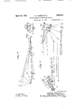
- FIG. 1 is a side view of a switch constructed in accordance with our invention
- Figure 2 is a fragmentary view showing the contacting end of the switch
- Figure 3 is a top plan view of the portion of the switch shown in Figure 2;
- Figure 4 is a diagrammatic view showing the manner of operationof the switch operating crank
- Figure 5 is a similar diagrammatic view showing the corresponding operation of the switch contact and of the switch blade.
- the switch shown in this figure comprises a grounded supporting base 1 which may be of a standard construction and may comprise a air of channel members secured together in spaced relationship, the channels being outwardly facing.
- Two insulators 2 and 3 are mounted on the channel at one end thereof.
- the insulator 2 is stationary whereas the insulator 3 is rotatable, said insulator being mounted on the base 1 by means of suitable anti-friction bearings 4 which may be of a construction such as shown in the pending application of Alfred Alsaker, Serial No. 137,926, filed September 27, 1926, althoughit is to be understood that any other preferred form of bearings may be used if desired.
- the insulators 2 and 3 are of substantially identical construction and comprise a number of petticoat insulators well known in the art and secured together in the usual manner.
- An actuating crank 5 ( Figure 4) is secured to the rotatable portion of the insulator bearing 4 for rotating the same.
- This crank may be of any desired construction.
- a crank such as is shown in the pending application 0 Alfred Alsaker and Elias G. Corneliussen, Serial No. 378,337, filed July 15, 1929, in that this permits any desired angular adjustment of the crank with respect to the insulator.
- Suitable electrostatic shields 6 and 7 are mounted upon the insulators 2 and 3 for reasons well known in the art.
- the insulators 2 and 3 are provided with a brace 9 for bracing one another.
- This brace 9 extends between the bracket member 10 that is mounted upon the insulator 2 and a member 11 upon the insulator 3, said bracket being journaled in a suitable bearing at the top of the member 11 in order to permit rotation of the insulator 3 with respect to the bracket member 9.
- the connecting bracing means 9 is here shown merely in diagrammatic form since the same may be of any approved construction. If desired this may take the form shown in the pending application of Alfred Alsaker, Thorsden Fjellstedt and Weldon 0. Hampton, Serial No. 350,708, filed March 28, 1929.
- a blade supporting member 15 in the form of a crank is pivoted on the bracket 10 at the ivot point 16 and is adapted to be rotated a out the pivot 16 as an axis.
- the crank 15 is provided with a socket into which a tubular blade 17 is secured in the usual manner.
- the blade is preferably a duraluminum drawn tube which is light in weight and which has a comparatively high conductivity.
- a counterweight 18 is adjustably secured to an arm that is secured to the crank 16 thereb counterbalancing the weight of the switc blade.
- a spindle 20 extends through the hearing about which the bracket 9 is journaled, said spindle being a part of the portion 11 that is secured to the insulator 3 and rotates therewith.
- a crank 21 is secured to the spindle 20 and is rotated thereby in a plane parallel to the base 1, and a connecting rod 22 connects the crank 21 with the crank 15.
- the connecting rod 22 is connected to the crank 21 by means of a universal joint 23 and is connected to the crank 15 by means of a universal joint 24.
- the joint 24 is made rather loose so as to permit a limited amount of play between the connecting rod 22 and the crank 15 for a purpose which will be apparent as the description proceeds. It is to be noted that the cranks 21 and 15 rotate in planes at right angles to one another.
- a terminal lug 28, for receiving a line conductor is secured to the bracket 9 and is connected to the switch blade 17 by means of a suitable, flexible braided copper conductor.
- crank arms 5 and 35 are connected together by means of a connectingirod 36.
- the rotating spindle portion of t e bearing 34 is extended below the base 1 and is adapted to receive a crank 37, of a construction similar to the cranks 5 and 35, for rotating the same.
- the crank 37 is adapted to be actuated, either by hand or by motor, in the usual manner in order to actuate the switch.
- actuation of the crank 37 the insulator 30 is rotated and by means of the crank 35, the connecting rod 36, and the crank 5 the insulator 3 is also rotated.
- the insulator 30 is provided with an electrostatic shield 38 of a construction similar to the shields 6 and 7 and rovided to reduce the concentration 0 electrostatic stresses at the end of the insulator, in a manner well known in the art.
- a generally cylindrical member 40 is secured to the top of the insulator 35 by means of the usual form of insulator cap and has a ball bearing member 41 mounted thereon.
- the ball bearing member 41 is rotatable with respect to the cylindrical member 40 and is of the nonfreezing type.
- a clam 42 is secured to the outer sleeve of the bearing 41 by means of a set of bolts indicated at 43, which bolts may constitute a swivel for the clamp.
- This clamp is rigid with the outer portion of the bearing 41 and is provided with a spilt sleeve 45 which is adapted to receive a line conductor 46 to anchor the same, said split sleeve being adapted to be clamped to the end of the line conductor 46 by means of a number of bolts 47 Upon rotation of the rotary insulator 30 the portion 40, which constitutes the. rotatable portion of the bearing 41 is rotated, the outer sleeve of the bearing 41 remaining stationary and serving as an anchor for the line conductor 46.
- An auxiliary arcing horn 50 is also secured to the member 42 by means of bolts 51.
- a stop 44 is formed integral with the outer s eeve of the bearing 41 and is provided with an n standing arm which constitutes a sto for t e switch blade.
- contact and arcing horn assembly 55 is mounted upon the inner portion of the bearign 41, that is upon the portion of the hearing that rotates as a unit with the insulator 35.
- This assembly comprises a contacting portion 56, which is of a generally I shaped cross-section in horizontal section, and a horn and uide portion 57 merging therewith.
- a exible braided conductor 59 connects the contact portion 56 with the bracket member 42 and the line conductor 46.
- the switch blade 17 has a forked or pronged contact secured thereto and adapted to cooperate with the contact 56. Both of these contacts are made of aluminum bronze reinforced with steel. The steel re inforcing rod of the contact 56 is indicated at 66.
- the forked contact 65 is protecting l6 against arcing by means of the arcing prongs 68 and 69 formed at the end thereof. Ball knobs 64 are also provided at the ends of the arcing prongs 68and 69 and at the end of the born 57.
- the line conductor 46 that is connected to the contact 56 may be anchored directly to the clamp 45, as shown in Figure 2, or it may be anchored thereto indirectly being first secured to the base 1 of the switch by means of an insulator indicated at 70 and the usual bracket constructions.
- crank 35 Upon the initial movement of the crank 35 from the position a to the position b the crank 5 is moved in a clockwise direction by the connecting rod 7 thereby moving from the position indicated at a to the position indicated at b.
- crank 35 reaches the position b it is almost in alignment with the connecting rod 7 and further rotation of crank 35 produces very little movement of the crank 5.
- crank 35 moves from the position b to the position 0 it passes out of alignment with the connecting rod 7 and causes the crank 5 to change its direction of rotation and it now commences to move in a counter-clockwise direction.
- the end of the crank 35 reaches the successive position indicated at 0, d, e and f the end of the crank 5 reaches the position indicated by the corresponding letters.
- the insulator 30 Since the pronged contact 65 is substantially stationary during this movement the insulator 30 produces a powerin] twisting effect tending to loosen the contact 56 from the contact 65. During this time there is no force tending to bend the insulator 30, hence the insulator is free of cantilever stresses.
- the switch blade 17 Upon movement of the rotary insulator 30 from the position d to the position 9 the switch blade 17 is rotated in a vertical plane about its axis 16.
- the auxiliary arcing horns 50 which are stationary, maintain contact with the prongs 68 and 69 and thereby prevent arcing between the contact 56 and the contact 65.
- any circuit that is to be interrupted is interrupted between the arcing prongs 68 and 69 and the main arcing horn 57 that is mounted upon the insulator 30.
- the crank 37 is rotated in the opposite direction to move the crank 35 from the position indicated at g to the position indicated at a.
- the switch blade 17 is swung rom its full open position, indicated in dotted lines in Figure 1, to substantially its full closed position indicated in that figure.
- the contact 56 is now in the position d and upon further actuation of the insulator 30 it is rotated to the position 0, thereby engaging the contact 65 with a powerful camming action to secure firm electrical engagement therewith.
- the joint 24 between the connecting rod 22 and the crank 15 is made rather loose in order to permit a limited amount of free play at that point. This prevents binding of the blade 17 against the stop 44.
- the prong 65 at the end of the switch blade 17 is provided with a rather large contacting surface. Full contact will be obtained between it and the contact 56 even though considerable looseness or lay should develop between the crank 35 an the switch blade 17, that is anywhere between the crank 35 and the connecting rod 36, or the connecting rod 36 and the crank 5, or between the crank 21 and the connecting rod 22, or at any of the hinges.
- the contact 56 is relatively short and it is driven directly by the operating mechanism and does not depend upon motion transmitted thereto from the switch blade actuating stack. This is a considerable improvement over the prior art in that play may be permitted in the switch blade operating mechanism due to the fact that there is a rather long contacting surface carried by the blade for engagement by the contact 57.
- cranks 35 and 21 By arranging the cranks 35 and 21 so that they pass through their positions of alignment with their respective connecting rods at substantially the same time or rather in quick succession we have obtained what corresponds to a usual lost motion connection since the actuating end of the connecting rod 22 has only a very slight motion during the movement of the crank 35 from the position a to the position d. If desired, enough play or looseness may be allowed in the knuckle 24 so that the switch blade remains entirely stationary during the turning of the crank35 from the position a to the position (1.
- Aluminum bronze is suggested for at least one of the cooperating switch contacts because of its hardness and resistance to wear, also because of its springy quality and resistance to corrosion.
- the fork is preferably of aluminum bronze since it must take most of the strain not only because of the contact action but also due to its sliding against the arcing horn.
- the rotating contact may be made of hard drawn copper if desired. If both the fork and the contact were made of copper the friction between them would be considerable not only due to the increased coeflicient of friction, but mainly because of the bindin action of the two films of copper oxide. ile the use of aluminum bronze contacts is preferred we do not wish to be limited to its use as copper or other metals may also be used.
- a switch comprising a rotatably mounted contact and a switch blade movable into engagement with the contact on the opposite sides of the axis of rotation of the contact, an axially rotatable insulator supporting and actuating the contact, and a stationary insulator and an axially rotatable insulator supporting and actuating the switch blade.
- a switch comprising a rotatably mounted contact, a switch blade movable into engagement with the contact on the opposite sides of the axis of rotation of the contact, and means for actuating the contact in ad vance of an appreciable actuation of the blade durin the switch opening movement, and means or actuating the blade, said last means comprisin a crank and a connectin rod and a secon crank and connecting r driven by the first crank and connecting rod, both cranks and their connecting rods passing through their dead center positions upon the initial switch opening operation to delay the opening movement of the blade.
- a switch comprising a blade pivoted at one end, a contact adapted to be engaged by the free end thereof, means adjacent the pivot of the blade for actuating the blade, and means for first oscillatin said first named means to tend to loosen t e o posite end of the blade from the contact, an then to swing the blade away from the contact.
- a switch comprising a pair of rotatable insulators, means or rotating one of the insulators, a lost motion connection between said insulators, said lost motion connection including a crank and a connecting rod and a second crank and connecting rod driven by the first crank and connecting rod, said cranks and connecting rods passing through their dead center positions at substantially the same time, a switch contact mounted on on of the insulators and rotated thereby, and a switch blade movable by the other insulator into and out of position for engaging said contact.
- a switch incluing a movable switch blade, a contact at the end thereof, a second contact adapted to be enga ed by the first contact and be wedged into rm engagement therewith, an insulator stack supporting the a second contact, means for actuating the second contact to loosen the engagement between the two while the switch blade is maintained substantiall stationary, and means for thereafter swinging said switch blade away from said second contact in a direction initially substantially axially of the insulator stack.
- An electric switch comprising a pair of substantially parallel rotary insulators each rotatable about its central axis, and cooperating contacts actuated by the respective insulators, one of the contacts being rotated about the axis of rotation of its insulator and the other being rotated about an axis at an angle to the axis of rotation of its insulator.
- An electric switch including a pair of crank arms, a connecting rod connectin the two, one of the cranks constituting the riv- I m crank and the other the driven crank, said driving crank having a normal switch open position and a switch closed position, said driving crank and connecting rod passing through dead center when moved from one of said positions to the other, and a second crank and connecting rod actuated by said driven crank and passing through dead center at aproximately the dead center position of the 10 rivin crank and connectin rod.
- electric switch including a pair of crank arms, a connecting rod connecting the two, one of the cranks constituting the driving crank and the other the driven crank,
- said driving crank having a normal switch open position and a switch closed position, said driving crank and connecting rod passing through dead center when moved from one of said positions to the other, and a second crank and connecting rod actuated by said driven crank and passing through dead center slightly after the first mentioned driving crank and connecting rod passing through their dead center position.
- An electric switch including a pair of cooperating contacts, means for actuating one of the contacts, means including a crank and a connecting rod and a second crank and a second connecting rod between the actuating means of the first contact and said second contact for actuating said second contact, said cranks and their respective connecting rods passin through dead center successively upon t e actuation of the switch.
- An electric switch including a pair of cooperating contacts, means for actuatin one of the contacts, means including a cran' 'and a connecting rod and a second crank and a second connecting rod between the actuating 40 means of the first contact and said second contact for actuating said second contact, said cranks and their respective connecting rods passing through dead center at substantially the same time upon the actuation of the switch.
- a switch including a movable switch blade,-a contact at the end thereof, a second contact adapted to be engaged by the first contact and be wedged into firm engagement therewith, an insulator stack supporting the second contact, means for actuatin the second contact to loosen the engagement between the two while the switch b ads is maintained substantially stationary, and means for thereafter swinging said switch blade away from said second contact in a direction initially substantially axially of the insulator stac [Qfiic'ial Gazette February 4, 1.936.]
- said driving crank having a normal switch open position and a switch closed position, said driving crank and connecting rod passing through dead center when moved from one of said positions to the other, and a second crank and connecting rod actuated by said driven crank and passing through dead center at aproximately the dead center position of the 10 rivin crank and connectin rod.
- electric switch including a pair of crank arms, a connecting rod connecting the two, one of the cranks constituting the driving crank and the other the driven crank,
- said driving crank having a normal switch open position and a switch closed position, said driving crank and connecting rod passing through dead center when moved from one of said positions to the other, and a second crank and connecting rod actuated by said driven crank and passing through dead center slightly after the first mentioned driving crank and connecting rod passing through their dead center position.
- An electric switch including a pair of cooperating contacts, means for actuating one of the contacts, means including a crank and a connecting rod and a second crank and a second connecting rod between the actuating means of the first contact and said second contact for actuating said second contact, said cranks and their respective connecting rods passin through dead center successively upon t e actuation of the switch.
- An electric switch including a pair of cooperating contacts, means for actuatin one of the contacts, means including a cran' 'and a connecting rod and a second crank and a second connecting rod between the actuating 40 means of the first contact and said second contact for actuating said second contact, said cranks and their respective connecting rods passing through dead center at substantially the same time upon the actuation of the switch.
- a switch including a movable switch blade,-a contact at the end thereof, a second contact adapted to be engaged by the first contact and be wedged into firm engagement therewith, an insulator stack supporting the second contact, means for actuatin the second contact to loosen the engagement between the two while the switch b ads is maintained substantially stationary, and means for thereafter swinging said switch blade away from said second contact in a direction initially substantially axially of the insulator stac [Qfiic'ial Gazette February 4, 1.936.]
Landscapes
- Mechanisms For Operating Contacts (AREA)
Description
April 19, 1932. A. ALSAKER ET AL 1,854,441
VERTICAL BREAK DISCONNECTING SWITCH Filed Jan. 10. 1950 :s Sheets-Sheet 1 April 19, 1932. A. ALSAKER ET AL 1,354,441
VERTICAL BREAK DISCONNECTING SWITCH Filed Jan. 10, 1950 s Shee ts-Sheet 2 A. ALSAKER ET AL VERTICAL BREAK DISGONNECTING SWITCH Filed Jan. 10, 1950 3 Sheets-Sheet 3 April 19, 1932.
Wed gkaker' weZdan H ZOZZ C72az-Z'e5 @471 oerrzez" Patented Apr. 19, 1932 UNITED STATES PATENT OFFICE ALFRED WELDON O. HAMPTON, AND CHARLES A. KOERNEB, OF CHICAGO, ILLINOIS, LSSIGNOBS TO THE DELTA-STAB ELEUIRIO GOIPANY, OF CHICAGO,
ILLINOIS, A. CORPORATION OF ILLINOIS VERTICAL BREAK DISGONNEUIING SWITCH Application filed January 10, 1930. Serial No. 419,776.
This invention relates to disconnect switches, and more particularly to such switches as are adapted for outdoor use, and preferably gang operation.
Switches of the kind here contemplated generally comprise a supporting base which 1s preferably grounded and upon which is mounted a contact supporting insulator and one or more switch blade supportin or actu- 1 ating insulators. In some types switches the contact supporting insulator is rotatable while in other types it is stationary. With increasing voltages the required spacing of the contact and the blade from one another and the spacing of both from the supporting base becomes very great. The insulators may be more than eight feet long and the blade may be more than twelve feet long. The insulator stacks are generally made of porcelain or other fran 'ble material and therefore are not able to withstand high stresses, especially in bending. Disconnect switches are infrequently operated, being required to stand rhaps for years in a given position, during 5 which time they are exposed to all sorts of adverse weather. While the switch is closed the contact and the end of the switch blade in engagement therewith may become corroded together. They may also become covered with sleet or ice. The difliculty of swinging a blade overtwelve feet long and mounted on an insulator over eight feet long, when the free end of the blade is held to its contact by ice, sleet and corrosion may be readily appreciated. Unless means is provided to break the hind between the blade and the contact any turning efiort applied to the blade actuating insulator may cause crackingl of the insu ator. In the prior art with w ich we are familiar this has been done by exerting either a longitudinal or a twisting motion to the blade prior to the swinging thereof away from the contact. This is not quite satisfactory in that it induces certain cantilever or bending stresses in the blade actuating insulator. In addition, if the bind between the blade and the contact is strong the contact may be drawn with the blade in its longitudinal movement thus causing bending and possible cracking of the contact supporting insulator. Other forms of ice breakin movements have been developed wherein t e contact as well as the blade are actuated to break the hind between them. These constructions of the past have been such that bending of the contact supporting insulator is not avoided in the event that the parts are rigidly frozen together thereby again subjecting the isulator to the danger of cracking.
It is one of the objects of the present invention to provide a high voltage disconnect switch having a powerful ice breaking movement and wherein the bending stresses in the insulators are reduced to a minimum or entirely eliminated. This is accomplished in one embodiment of our invention by making the contact suporting insulator rotatable and providing engagement between the contact and the blade on the opposite sides of the axis of rotation of the contact. To open the switch the contact is first turned so as to twist the same free of an bind between it and the blade, and then the lads is swun to the open position. Due to the fact that t e contact is engaged by the blade on the opposite sides of its axis of rotation the bending stress in the contact su porting insulator is eliminated. During t is ice breaking movement the switch blade may be maintained stationary or it may be given a slight reciprocating or oscillating movement to assist in breaking the hind between it and the contact.
The contacts are preferably of the pressure area type. The design is such as to obtain as much contact area as possible. When this is done the pressure need not be tremendously high in order to carry say 600 amperes continuously. The contacting ends of the blade and contact are so constructed as to relieve the pressure between them when the contact is rotated to open the switch, thereby relieving the switch blade and its supporting insulator of the stress otherwise incident to the overcoming of this pressure when the switch is to be opened. The contact design is such that the full contact area and pressure will be obtained even though lost motion should develop in the operating mechanism. This is accomplished, in the embodiment herein illustrated, by making one of the contact engaging portions in the form of a prong which is adapted to embrace the other contact after which one of the contacts is twisted or turned into firm engagement with the other. As shown the prong is mounted at the end of the switch blade and is adapted to receive its cooperating contact between its tines. Th's may be reversed without departing from the spirit or scope of the present invention. Our contact construction is novel per se and constitutes a distinct improvement over the prior art. Arcing horns are provided, the construction being such that the horns l kewise function as guides for the switch blade. An auxiliary horn is provided for preventing arcing to the switch stop when the switch opening movement is initiated.
The attainment of the above and further objects of the present invention will be apparent from the following specification taken in conjunction with the accompanying drawings illustrating a preferred embodiment of our invention.
In the drawings:
Figure 1 is a side view of a switch constructed in accordance with our invention;
Figure 2 is a fragmentary view showing the contacting end of the switch;
Figure 3 is a top plan view of the portion of the switch shown in Figure 2;
Figure 4 is a diagrammatic view showing the manner of operationof the switch operating crank;
Figure 5 is a similar diagrammatic view showing the corresponding operation of the switch contact and of the switch blade.
Reference may now be had more particularly to Figure 1. The switch shown in this figure comprises a grounded supporting base 1 which may be of a standard construction and may comprise a air of channel members secured together in spaced relationship, the channels being outwardly facing. Two insulators 2 and 3 are mounted on the channel at one end thereof. The insulator 2 is stationary whereas the insulator 3 is rotatable, said insulator being mounted on the base 1 by means of suitable anti-friction bearings 4 which may be of a construction such as shown in the pending application of Alfred Alsaker, Serial No. 137,926, filed September 27, 1926, althoughit is to be understood that any other preferred form of bearings may be used if desired. The insulators 2 and 3 are of substantially identical construction and comprise a number of petticoat insulators well known in the art and secured together in the usual manner. An actuating crank 5 (Figure 4) is secured to the rotatable portion of the insulator bearing 4 for rotating the same. This crank may be of any desired construction. We prefer to use a crank such as is shown in the pending application 0 Alfred Alsaker and Elias G. Corneliussen, Serial No. 378,337, filed July 15, 1929, in that this permits any desired angular adjustment of the crank with respect to the insulator. Suitable electrostatic shields 6 and 7 are mounted upon the insulators 2 and 3 for reasons well known in the art. The insulators 2 and 3 are provided with a brace 9 for bracing one another. This brace 9 extends between the bracket member 10 that is mounted upon the insulator 2 and a member 11 upon the insulator 3, said bracket being journaled in a suitable bearing at the top of the member 11 in order to permit rotation of the insulator 3 with respect to the bracket member 9. The connecting bracing means 9 is here shown merely in diagrammatic form since the same may be of any approved construction. If desired this may take the form shown in the pending application of Alfred Alsaker, Thorsden Fjellstedt and Weldon 0. Hampton, Serial No. 350,708, filed March 28, 1929. A blade supporting member 15 in the form of a crank is pivoted on the bracket 10 at the ivot point 16 and is adapted to be rotated a out the pivot 16 as an axis. The crank 15 is provided with a socket into which a tubular blade 17 is secured in the usual manner. The blade is preferably a duraluminum drawn tube which is light in weight and which has a comparatively high conductivity. A counterweight 18 is adjustably secured to an arm that is secured to the crank 16 thereb counterbalancing the weight of the switc blade. A spindle 20 extends through the hearing about which the bracket 9 is journaled, said spindle being a part of the portion 11 that is secured to the insulator 3 and rotates therewith. A crank 21 is secured to the spindle 20 and is rotated thereby in a plane parallel to the base 1, and a connecting rod 22 connects the crank 21 with the crank 15. The connecting rod 22 is connected to the crank 21 by means of a universal joint 23 and is connected to the crank 15 by means of a universal joint 24. The joint 24 is made rather loose so as to permit a limited amount of play between the connecting rod 22 and the crank 15 for a purpose which will be apparent as the description proceeds. It is to be noted that the cranks 21 and 15 rotate in planes at right angles to one another. A terminal lug 28, for receiving a line conductor, is secured to the bracket 9 and is connected to the switch blade 17 by means of a suitable, flexible braided copper conductor.
An insulator 30, which may be of any approved construction, is rotatably mounted upon the base 1 by means of a bearing 34 which may be of a construction similar to cured to the bearing 4 of the insulator 3. The
crank arms 5 and 35 are connected together by means of a connectingirod 36. The rotating spindle portion of t e bearing 34 is extended below the base 1 and is adapted to receive a crank 37, of a construction similar to the cranks 5 and 35, for rotating the same. The crank 37 is adapted to be actuated, either by hand or by motor, in the usual manner in order to actuate the switch. Upon actuation of the crank 37 the insulator 30 is rotated and by means of the crank 35, the connecting rod 36, and the crank 5 the insulator 3 is also rotated. The insulator 30 is provided with an electrostatic shield 38 of a construction similar to the shields 6 and 7 and rovided to reduce the concentration 0 electrostatic stresses at the end of the insulator, in a manner well known in the art. A generally cylindrical member 40 is secured to the top of the insulator 35 by means of the usual form of insulator cap and has a ball bearing member 41 mounted thereon. The ball bearing member 41 is rotatable with respect to the cylindrical member 40 and is of the nonfreezing type. A clam 42 is secured to the outer sleeve of the bearing 41 by means of a set of bolts indicated at 43, which bolts may constitute a swivel for the clamp. This clamp is rigid with the outer portion of the bearing 41 and is provided with a spilt sleeve 45 which is adapted to receive a line conductor 46 to anchor the same, said split sleeve being adapted to be clamped to the end of the line conductor 46 by means of a number of bolts 47 Upon rotation of the rotary insulator 30 the portion 40, which constitutes the. rotatable portion of the bearing 41 is rotated, the outer sleeve of the bearing 41 remaining stationary and serving as an anchor for the line conductor 46. An auxiliary arcing horn 50 is also secured to the member 42 by means of bolts 51. A stop 44 is formed integral with the outer s eeve of the bearing 41 and is provided with an n standing arm which constitutes a sto for t e switch blade.
contact and arcing horn assembly 55 is mounted upon the inner portion of the bearign 41, that is upon the portion of the hearing that rotates as a unit with the insulator 35. This assembly comprises a contacting portion 56, which is of a generally I shaped cross-section in horizontal section, and a horn and uide portion 57 merging therewith. A exible braided conductor 59 connects the contact portion 56 with the bracket member 42 and the line conductor 46.
The switch blade 17 has a forked or pronged contact secured thereto and adapted to cooperate with the contact 56. Both of these contacts are made of aluminum bronze reinforced with steel. The steel re inforcing rod of the contact 56 is indicated at 66. The forked contact 65 is protecting l6 against arcing by means of the arcing prongs 68 and 69 formed at the end thereof. Ball knobs 64 are also provided at the ends of the arcing prongs 68and 69 and at the end of the born 57.
The line conductor 46 that is connected to the contact 56 may be anchored directly to the clamp 45, as shown in Figure 2, or it may be anchored thereto indirectly being first secured to the base 1 of the switch by means of an insulator indicated at 70 and the usual bracket constructions.
A description will now be given of the manner of operation of the switch when the crank 37 is manipulated to open it and for this purpose reference may be had to Figures 4 and 5 which show the position of the various operating cranks when the switch is closed. To open the switch the crank 37 is rotated to rotate the insulator 30. The rotation is in a counter-clockwise direction, as seen in Figure 4. The insulator 30 is rotated so as to rotate the crank 35 from the position indicated at a to the position indicated at g. At the commencement of operation the various parts are in the position indicatedby the letter a.
Upon the initial movement of the crank 35 from the position a to the position b the crank 5 is moved in a clockwise direction by the connecting rod 7 thereby moving from the position indicated at a to the position indicated at b. When the crank 35 reaches the position b it is almost in alignment with the connecting rod 7 and further rotation of crank 35 produces very little movement of the crank 5. As the crank 35 moves from the position b to the position 0 it passes out of alignment with the connecting rod 7 and causes the crank 5 to change its direction of rotation and it now commences to move in a counter-clockwise direction. When the end of the crank 35 reaches the successive position indicated at 0, d, e and f the end of the crank 5 reaches the position indicated by the corresponding letters. In Figure 5 we have indicated the position of the actuating end of the crank 21 and of the actuating end of the connecting rod 22 corresponding to the positions a to g, respectively,of Figure 4, said positions being given corresponding reference letters. It must be remembered that the crank 21 rotates with the insulator 3 as a unit being keyed thereto, hence the motion of the crank 21 will be identical with the motion of the end of the crank 5. Thus the crank 21 moves first in a clockwise direction from its initial position a to the position 5, and thereafter moves in a counterclockwise direction from the position b to left as seen in Figure 5. Upon reversal of the position g. Upon the initial movement direction of rotation of the crank 21 from the position b to the position 0 the end of the connecting rod that is connected to the crank 15 is moved to the right as seen in Figure 5, said motion being also a very slight amount. At the position a the crank 21 and the connecting rod 22 are almost in alignment and therefore the continued movement of the crank 21 produces substantially no effect upon the remote end of the connecting rod 22. It is to be noted that while the crank 21 is moving from position a to the position b and from the position 6 toward the position a that the crank 35 and the connecting rod 7 are passing through their position of alignment, hence the movement imparted by the crank 35 to the crank 21 is very slight. As the crank 35 passes from the position b to the position 0 the crank 21 and the connecting rod 22 approach alignment, hence the amount of motion imparted to the connecting rod 22 at this time is also very slight. Continued rotation of the crank 21 beyond the position 0 causes it to pass dead center with the crank 22 and thereafter the rotation of the crank 21 brings about a movement of the end of the connecting rod 22 that is connected to the crank 15 said movement bein in a direction toward the left, as seen in igure 5. It may be seen from this figure that during the interval taken for the crank 35 to travel from the position a to the position 03 that the joint 24 is moved a very slight amount, the motion being first slightly to the left, then to the right, and then back to the left. Upon movement of the crank 35 from the position d to the final full open position indicated at g the knuckle 24 is moved to the corresponding position indicated in Figure 5. The motion of the crank 35 from the position a to the position d is the ice-breaking movement. During this interval the contact 56 is moved from the position indicated at a to the position indicated at 6 thereby bringing it substantially out of contact with the ronged portion 65. It is to be noted that tile contact is rotated about its center which is also the center of the rotating insulator stack 30 and that the contact 56 is engaged by the prongs of the contact on the opposite side of the axis of rotation of the insulator 30. Since the pronged contact 65 is substantially stationary during this movement the insulator 30 produces a powerin] twisting effect tending to loosen the contact 56 from the contact 65. During this time there is no force tending to bend the insulator 30, hence the insulator is free of cantilever stresses. Upon movement of the rotary insulator 30 from the position d to the position 9 the switch blade 17 is rotated in a vertical plane about its axis 16. During the initial switch opening movement the auxiliary arcing horns 50, which are stationary, maintain contact with the prongs 68 and 69 and thereby prevent arcing between the contact 56 and the contact 65. As the switch blade is swung out of engagement with the contact and out of engagement with the arcing horns 50 any circuit that is to be interrupted is interrupted between the arcing prongs 68 and 69 and the main arcing horn 57 that is mounted upon the insulator 30.
To close the switch the crank 37 is rotated in the opposite direction to move the crank 35 from the position indicated at g to the position indicated at a. During the initial movement of the actuating insulator, that is during the movement from the position g to the osition d the switch blade 17 is swung rom its full open position, indicated in dotted lines in Figure 1, to substantially its full closed position indicated in that figure. The contact 56 is now in the position d and upon further actuation of the insulator 30 it is rotated to the position 0, thereby engaging the contact 65 with a powerful camming action to secure firm electrical engagement therewith. As previously pointed out, the joint 24 between the connecting rod 22 and the crank 15 is made rather loose in order to permit a limited amount of free play at that point. This prevents binding of the blade 17 against the stop 44.
Attention is called to the fact that the prong 65 at the end of the switch blade 17 is provided with a rather large contacting surface. Full contact will be obtained between it and the contact 56 even though considerable looseness or lay should develop between the crank 35 an the switch blade 17, that is anywhere between the crank 35 and the connecting rod 36, or the connecting rod 36 and the crank 5, or between the crank 21 and the connecting rod 22, or at any of the hinges. The contact 56 is relatively short and it is driven directly by the operating mechanism and does not depend upon motion transmitted thereto from the switch blade actuating stack. This is a considerable improvement over the prior art in that play may be permitted in the switch blade operating mechanism due to the fact that there is a rather long contacting surface carried by the blade for engagement by the contact 57. However, if the blade actuating insulator were directly connected to the operating mechanism and if the insulator actuating the contact 56 were actuated from the insulator 3 then any play that might develop in the connection would result in a failure of the contact 56 establishing firm electrical engagement with the contact 55. This is due to the fact that if, due to play, the contact 56 upon closing should stop in the position 6 rather than in position a poor electrical engagement would be obtained, whereas if the switch blade 17 were to stop in its position 6, upon closing, due to play or lost motion that may develop in the connection then good electrical engagement would nevertheless be obtained.
It is to be noted that by arranging the cranks 35 and 21 so that they pass through their positions of alignment with their respective connecting rods at substantially the same time or rather in quick succession we have obtained what corresponds to a usual lost motion connection since the actuating end of the connecting rod 22 has only a very slight motion during the movement of the crank 35 from the position a to the position d. If desired, enough play or looseness may be allowed in the knuckle 24 so that the switch blade remains entirely stationary during the turning of the crank35 from the position a to the position (1.
Aluminum bronze is suggested for at least one of the cooperating switch contacts because of its hardness and resistance to wear, also because of its springy quality and resistance to corrosion. The fork is preferably of aluminum bronze since it must take most of the strain not only because of the contact action but also due to its sliding against the arcing horn. The rotating contact may be made of hard drawn copper if desired. If both the fork and the contact were made of copper the friction between them would be considerable not only due to the increased coeflicient of friction, but mainly because of the bindin action of the two films of copper oxide. ile the use of aluminum bronze contacts is preferred we do not wish to be limited to its use as copper or other metals may also be used.
In compliance with the requirements of the patent statutes we have herein shown and described a preferred embodiment of our invention. It is, however, to be understood that the invention is not limited to the precise instruction herein shown, the same being merely illustrative of the invention. What we consider new and desire to secure by Letters Patent is:
1. The method of separating a switch blade from its contact which comprises, turning the contact about a short radius and at the same time producing a slight reciprocating movement of the end of the blade that is in engagement with the contact to break the hind between the contact and the blade, and then actuating the blade to the full open position.
2. A switch comprising a rotatably mounted contact and a switch blade movable into engagement with the contact on the opposite sides of the axis of rotation of the contact, an axially rotatable insulator supporting and actuating the contact, and a stationary insulator and an axially rotatable insulator supporting and actuating the switch blade.
3. A switch comprising a rotatably mounted contact, a switch blade movable into engagement with the contact on the opposite sides of the axis of rotation of the contact, and means for actuating the contact in ad vance of an appreciable actuation of the blade durin the switch opening movement, and means or actuating the blade, said last means comprisin a crank and a connectin rod and a secon crank and connecting r driven by the first crank and connecting rod, both cranks and their connecting rods passing through their dead center positions upon the initial switch opening operation to delay the opening movement of the blade.
4. A switch comprising a blade pivoted at one end, a contact adapted to be engaged by the free end thereof, means adjacent the pivot of the blade for actuating the blade, and means for first oscillatin said first named means to tend to loosen t e o posite end of the blade from the contact, an then to swing the blade away from the contact. a
5. .A switch comprising a pair of rotatable insulators, means or rotating one of the insulators, a lost motion connection between said insulators, said lost motion connection including a crank and a connecting rod and a second crank and connecting rod driven by the first crank and connecting rod, said cranks and connecting rods passing through their dead center positions at substantially the same time, a switch contact mounted on on of the insulators and rotated thereby, and a switch blade movable by the other insulator into and out of position for engaging said contact.
6. A switch com rising a contact anda switch blade movab e into and out of contact making engagement with one another, means for actuating the contact, means for actuating the blade, and a common actuating means for both of said means, there being a lost motion between the common actuating means and the switch blade actuatin means.
7. A switch inclu ing a movable switch blade, a contact at the end thereof, a second contact adapted to be enga ed by the first contact and be wedged into rm engagement therewith, an insulator stack supporting the a second contact, means for actuating the second contact to loosen the engagement between the two while the switch blade is maintained substantiall stationary, and means for thereafter swinging said switch blade away from said second contact in a direction initially substantially axially of the insulator stack.
8. An electric switch comprising a pair of substantially parallel rotary insulators each rotatable about its central axis, and cooperating contacts actuated by the respective insulators, one of the contacts being rotated about the axis of rotation of its insulator and the other being rotated about an axis at an angle to the axis of rotation of its insulator.
9. An electric switch including a pair of crank arms, a connecting rod connectin the two, one of the cranks constituting the riv- I m crank and the other the driven crank, said driving crank having a normal switch open position and a switch closed position, said driving crank and connecting rod passing through dead center when moved from one of said positions to the other, and a second crank and connecting rod actuated by said driven crank and passing through dead center at aproximately the dead center position of the 10 rivin crank and connectin rod.
10. n electric switch including a pair of crank arms, a connecting rod connecting the two, one of the cranks constituting the driving crank and the other the driven crank,
said driving crank having a normal switch open position and a switch closed position, said driving crank and connecting rod passing through dead center when moved from one of said positions to the other, and a second crank and connecting rod actuated by said driven crank and passing through dead center slightly after the first mentioned driving crank and connecting rod passing through their dead center position.
11. An electric switch including a pair of cooperating contacts, means for actuating one of the contacts, means including a crank and a connecting rod and a second crank and a second connecting rod between the actuating means of the first contact and said second contact for actuating said second contact, said cranks and their respective connecting rods passin through dead center successively upon t e actuation of the switch.
12. An electric switch including a pair of cooperating contacts, means for actuatin one of the contacts, means including a cran' 'and a connecting rod and a second crank and a second connecting rod between the actuating 40 means of the first contact and said second contact for actuating said second contact, said cranks and their respective connecting rods passing through dead center at substantially the same time upon the actuation of the switch.
In witness whereof, we hereunto subscribe our names this 7th day of January, 1930.
ALFRED ALSAKER. WELDON O. HAMPTON. CHARLES A. KOERNER.
DISCLAIMER 1,854,441.Alfred Alsaker, Weldon 0. Hampton, and Charles A. Koerner, Chicago, VERTICAL BREAK DIBCONNECTING Swrrcn. Patent dated A r. 19, 1932. Disclaimer filed January 6, 1936, by the assignee, The De tat-Star Electric, Company, the patentees joining and concurring. Hereby enters this disclaimer to that claim which is numbered 7 in said patent, and which is in the following words, to wit:
7. A switch including a movable switch blade,-a contact at the end thereof, a second contact adapted to be engaged by the first contact and be wedged into firm engagement therewith, an insulator stack supporting the second contact, means for actuatin the second contact to loosen the engagement between the two while the switch b ads is maintained substantially stationary, and means for thereafter swinging said switch blade away from said second contact in a direction initially substantially axially of the insulator stac [Qfiic'ial Gazette February 4, 1.936.]
I m crank and the other the driven crank, said driving crank having a normal switch open position and a switch closed position, said driving crank and connecting rod passing through dead center when moved from one of said positions to the other, and a second crank and connecting rod actuated by said driven crank and passing through dead center at aproximately the dead center position of the 10 rivin crank and connectin rod.
10. n electric switch including a pair of crank arms, a connecting rod connecting the two, one of the cranks constituting the driving crank and the other the driven crank,
said driving crank having a normal switch open position and a switch closed position, said driving crank and connecting rod passing through dead center when moved from one of said positions to the other, and a second crank and connecting rod actuated by said driven crank and passing through dead center slightly after the first mentioned driving crank and connecting rod passing through their dead center position.
11. An electric switch including a pair of cooperating contacts, means for actuating one of the contacts, means including a crank and a connecting rod and a second crank and a second connecting rod between the actuating means of the first contact and said second contact for actuating said second contact, said cranks and their respective connecting rods passin through dead center successively upon t e actuation of the switch.
12. An electric switch including a pair of cooperating contacts, means for actuatin one of the contacts, means including a cran' 'and a connecting rod and a second crank and a second connecting rod between the actuating 40 means of the first contact and said second contact for actuating said second contact, said cranks and their respective connecting rods passing through dead center at substantially the same time upon the actuation of the switch.
In witness whereof, we hereunto subscribe our names this 7th day of January, 1930.
ALFRED ALSAKER. WELDON O. HAMPTON. CHARLES A. KOERNER.
DISCLAIMER 1,854,441.Alfred Alsaker, Weldon 0. Hampton, and Charles A. Koerner, Chicago, VERTICAL BREAK DIBCONNECTING Swrrcn. Patent dated A r. 19, 1932. Disclaimer filed January 6, 1936, by the assignee, The De tat-Star Electric, Company, the patentees joining and concurring. Hereby enters this disclaimer to that claim which is numbered 7 in said patent, and which is in the following words, to wit:
7. A switch including a movable switch blade,-a contact at the end thereof, a second contact adapted to be engaged by the first contact and be wedged into firm engagement therewith, an insulator stack supporting the second contact, means for actuatin the second contact to loosen the engagement between the two while the switch b ads is maintained substantially stationary, and means for thereafter swinging said switch blade away from said second contact in a direction initially substantially axially of the insulator stac [Qfiic'ial Gazette February 4, 1.936.]
Priority Applications (1)
| Application Number | Priority Date | Filing Date | Title |
|---|---|---|---|
| US419776A US1854441A (en) | 1930-01-10 | 1930-01-10 | Vertical break disconnecting switch |
Applications Claiming Priority (1)
| Application Number | Priority Date | Filing Date | Title |
|---|---|---|---|
| US419776A US1854441A (en) | 1930-01-10 | 1930-01-10 | Vertical break disconnecting switch |
Publications (1)
| Publication Number | Publication Date |
|---|---|
| US1854441A true US1854441A (en) | 1932-04-19 |
Family
ID=23663712
Family Applications (1)
| Application Number | Title | Priority Date | Filing Date |
|---|---|---|---|
| US419776A Expired - Lifetime US1854441A (en) | 1930-01-10 | 1930-01-10 | Vertical break disconnecting switch |
Country Status (1)
| Country | Link |
|---|---|
| US (1) | US1854441A (en) |
Cited By (3)
| Publication number | Priority date | Publication date | Assignee | Title |
|---|---|---|---|---|
| US2905794A (en) * | 1956-06-22 | 1959-09-22 | Westinghouse Electric Corp | Electric switch |
| US4112268A (en) * | 1976-12-01 | 1978-09-05 | H. K. Porter Company, Inc. | Double side air break disconnecting switch |
| FR2981216A1 (en) * | 2011-10-11 | 2013-04-12 | Schneider Electric Ind Sas | MOUNTING MEMBER FOR CURRENT DISTRIBUTION CELL DISCONNECT SWITCHING CONTACT |
-
1930
- 1930-01-10 US US419776A patent/US1854441A/en not_active Expired - Lifetime
Cited By (4)
| Publication number | Priority date | Publication date | Assignee | Title |
|---|---|---|---|---|
| US2905794A (en) * | 1956-06-22 | 1959-09-22 | Westinghouse Electric Corp | Electric switch |
| US4112268A (en) * | 1976-12-01 | 1978-09-05 | H. K. Porter Company, Inc. | Double side air break disconnecting switch |
| FR2981216A1 (en) * | 2011-10-11 | 2013-04-12 | Schneider Electric Ind Sas | MOUNTING MEMBER FOR CURRENT DISTRIBUTION CELL DISCONNECT SWITCHING CONTACT |
| EP2581923A1 (en) * | 2011-10-11 | 2013-04-17 | Schneider Electric Industries SAS | Mounting member for a contact of an isolation switch in a current distribution cell |
Similar Documents
| Publication | Publication Date | Title |
|---|---|---|
| US1854441A (en) | Vertical break disconnecting switch | |
| US2531165A (en) | Electric switch | |
| US2363360A (en) | Circuit interrupter | |
| US2306117A (en) | Electric switch | |
| US3005063A (en) | Self-aligning switch | |
| US3590178A (en) | Disconnecting switch having improved operating mechanism | |
| US2779830A (en) | High voltage switch | |
| US3588406A (en) | High voltage beaver tail type switch with preinsertion resistor | |
| US1901688A (en) | Horizontal break disconnecting switch | |
| US1815392A (en) | Switch | |
| CA3128780C (en) | High voltage vertical break disconnect switch with planetary gear reduction switch drive mechanism | |
| US2462342A (en) | Operating mechanism for electrical switches | |
| US2741672A (en) | Dual axis rotatable blade switch | |
| US3047685A (en) | High voltage disconnect switch | |
| US2154665A (en) | Switch | |
| US1584612A (en) | Circuit breaker | |
| US2194021A (en) | Electric switch | |
| US2303496A (en) | Circuit interrupter | |
| US2041877A (en) | Disconnecting switch | |
| US1901689A (en) | Switch | |
| US3731018A (en) | Disconnecting switch operating linkage | |
| US1952436A (en) | Switch | |
| US3879588A (en) | Center break disconnect switch | |
| US2264862A (en) | Electric switch | |
| US2426009A (en) | Electric switch |