US1854419A - Window construction - Google Patents
Window construction Download PDFInfo
- Publication number
- US1854419A US1854419A US449950A US44995030A US1854419A US 1854419 A US1854419 A US 1854419A US 449950 A US449950 A US 449950A US 44995030 A US44995030 A US 44995030A US 1854419 A US1854419 A US 1854419A
- Authority
- US
- United States
- Prior art keywords
- window
- frame
- bottom window
- alignment
- sides
- Prior art date
- Legal status (The legal status is an assumption and is not a legal conclusion. Google has not performed a legal analysis and makes no representation as to the accuracy of the status listed.)
- Expired - Lifetime
Links
- 238000010276 construction Methods 0.000 title description 18
- 239000011324 bead Substances 0.000 description 2
- 241001074085 Scophthalmus aquosus Species 0.000 description 1
- 238000007789 sealing Methods 0.000 description 1
- 210000002105 tongue Anatomy 0.000 description 1
- 238000005406 washing Methods 0.000 description 1
Images

Classifications
-
- E—FIXED CONSTRUCTIONS
- E06—DOORS, WINDOWS, SHUTTERS, OR ROLLER BLINDS IN GENERAL; LADDERS
- E06B—FIXED OR MOVABLE CLOSURES FOR OPENINGS IN BUILDINGS, VEHICLES, FENCES OR LIKE ENCLOSURES IN GENERAL, e.g. DOORS, WINDOWS, BLINDS, GATES
- E06B3/00—Window sashes, door leaves, or like elements for closing wall or like openings; Layout of fixed or moving closures, e.g. windows in wall or like openings; Features of rigidly-mounted outer frames relating to the mounting of wing frames
- E06B3/32—Arrangements of wings characterised by the manner of movement; Arrangements of movable wings in openings; Features of wings or frames relating solely to the manner of movement of the wing
- E06B3/50—Arrangements of wings characterised by the manner of movement; Arrangements of movable wings in openings; Features of wings or frames relating solely to the manner of movement of the wing with more than one kind of movement
- E06B3/5054—Arrangements of wings characterised by the manner of movement; Arrangements of movable wings in openings; Features of wings or frames relating solely to the manner of movement of the wing with more than one kind of movement where the sliding and rotating movements are independent of each other
- E06B3/5063—Arrangements of wings characterised by the manner of movement; Arrangements of movable wings in openings; Features of wings or frames relating solely to the manner of movement of the wing with more than one kind of movement where the sliding and rotating movements are independent of each other the vertical sliding wings having the possibility of an additional rotational movement
-
- E—FIXED CONSTRUCTIONS
- E06—DOORS, WINDOWS, SHUTTERS, OR ROLLER BLINDS IN GENERAL; LADDERS
- E06B—FIXED OR MOVABLE CLOSURES FOR OPENINGS IN BUILDINGS, VEHICLES, FENCES OR LIKE ENCLOSURES IN GENERAL, e.g. DOORS, WINDOWS, BLINDS, GATES
- E06B3/00—Window sashes, door leaves, or like elements for closing wall or like openings; Layout of fixed or moving closures, e.g. windows in wall or like openings; Features of rigidly-mounted outer frames relating to the mounting of wing frames
- E06B3/32—Arrangements of wings characterised by the manner of movement; Arrangements of movable wings in openings; Features of wings or frames relating solely to the manner of movement of the wing
- E06B3/50—Arrangements of wings characterised by the manner of movement; Arrangements of movable wings in openings; Features of wings or frames relating solely to the manner of movement of the wing with more than one kind of movement
Definitions
- My invention relates to improvements in window constructions, and it consists in the combinations, constructions, and arrangements herein described and claimed.
- An object of my invention is to provide a window construction having novel means for weatherproofing movable windows.
- a further object is to provide a window construction having novel means whereby both sides of the windowpanes are made accessible for washing from the inside of the building.
- a further object is to provide a window construction having top and bottom windows, the top window being removable from the frame without removing the bottom window.
- a further object is to provide a window construction having novel means for swinging the bottom window inwardly or raising the same.
- a further object is to provide a device of the type described having novel means for opening aligned windows.
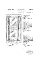
- Figure 1 is an inside front elevation of the window construction, the window frame being shown in section,
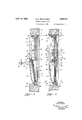
- Figure 2 is a section taken along the line 2-2 of Figure 1, I
- Figure 3 is a View similar to that of Figure 2 showing the bottom window in the first stage of being opened, I
- Figure 4 is a view similar to that of Figure 2 showing the bottom window in the sec- 0nd stage of being opened
- Figure 5 is a section showing the position of the bottom window for opening the top window, the top window being shown in the open position whereby'it may be removed from the window frame,
- Figure 6 is a section taken along the line 66 of- Figure 2,
- Figure 7 is a section taken along the line 7-7 of Figure 2
- Figure 8 is a section taken along the line 88 of Figure 2.
- a window frame 1 mounted in a wall 2. Disposed within vthe frame 1 is a top window 3, having a sash 4, and a bottom window 5, having a sash 6.
- the sashes 4. and 6 are in alignment when the windows are closed as shown in Figure 2.
- the sides of the window frame are provided with vertically extending weather strips7 abutting the outside surfaces of the side portions 8 of the top and bottom window sashes.
- the frame 1 is provided with a vertically extend ing groove 9 for receiving the tongues 10 of the weather strips 7. This construction provides a weatherproof and positive means for fastening the weather strips to the frame.
- the weather strips 7 are provided with bead portions 11 which extend throughout their length and which are receivable in beaded recesses 12 of the side portions 8. This bead construction provides a means for positively sealing the joint between the window frame and the weather strip for making it weatherproof.
- FIG. 1 shows a detail of this construction.
- a Z-shaped catch member 13 is mounted on the frame, a portion 14 thereof being spaced away from the frame.
- An angle member 15 is secured to the topinside face of the sash 4:, its projecting flange 16 being adjacent the portion 14 of the catch member 13.
- the flange 16 is provided with a projecting lug 17 rotatably receivable in a slot 18 in the portion 14 of the Z-shaped catch member 13.
- the slot is best shown in Figure 5.
- This structure is provided at each side of the top window sash for securing the sash to the frame.
- the top window sash is released, it may be swung inwardly.
- Figure 5 shows that when the top window is in its raised position, 1
- Each side of the window frame is provided with a vertically extending slot 19, see Figure 2.
- the lower end of the slot 19 merges with a horizontally extending slot 20.
- the slot 19 is extended for a short distance beyond the horizontal slot 20 as at 21 for a purpose hereinafter described.
- Each side of the frame 1 is provided with a resilient member 22 having one end 23 securely fastened thereto, the free end 24 extending between the top window sash and the frame for holding the top window in position when the bottom window is swung inwardly.
- Each side of the frame is provided with a lever arm 25 pivotally mounted to the frame at 26, see Figure 2.
- the resilient member 22 is provided with a small recess 27, as shown in Figures 7 and 3, for receiving a protuberance 28 of the lever arm 25 when it is in the position shown in Figure 2.
- An arm 29 has one end pivotally connected to the lever arm 25 at 30, and the other end pivotally connected at 31 to a projecting member 32.
- a knob 30' is mounted on the arm 29 at its pivotal point 30, whereby the arm may be easily actuated.
- the projecting member 32 is secured to the top inside face of the bottom window sash at the side adjacent the frame.
- the base portion of the projecting member 32 is provided with a secondary projecting portion 33 which extends between the window sash and the lever arm 29, when the same is in the position shown in Figure 2, which serves to keep the window sashes tightly held against the weather strips 7. It will be seen by referring to Figure 1, that this structure is provided on each side of the window frame.
- the bottom portion of the sash of the top window has a projecting portion or flange 34, at its outside edge, which extends throughout its length.
- the outside top edge of the bottom window sash is provided with a longitudinal recess 35 extending throughout its length.
- This construction makes. the juncture of the top and bottom window sashes weatherproof. This construction also serves to keep the top window sash tightly pressed against the weather strips 7 by the action of the arm 29 on the projection 33 when the windows are in the position shown in Figure 2.
- each side of the bottom window sash adjacent its top edge is provided with a pin which extends throughthe slot 20 and into the box portion 37 of the window frame 1.
- a chain, cable, or the like has one end connected to the pin 36.
- the cable 38 extends over a pulley 39 mounted to the window frame at 10, and has its other end con nected to a window weight 41.
- Each side of the frame 1 is also provided with a track 42, of the shape shown in Figure 2, which is secured to the frame by any suitable means such as screws or the like.
- Catch members i3 are attached to the bottom portion. of t is bottom window sash adjacent the sides thereof.
- Each catch mem ber i3 comprises a housing -14 which may be secured to the window sash 8 by any suitable means such as screws
- a shoe 16 is provided which rides on the track 42.
- the shoe 16 is rigidly connected to a slidable pin 4;? which extends within the housing 14 and is connected to an actuating lever 48.
- the actuating lever extends without the housing whereby the lever may be grasped for disconnecting the shoe 416 from the track 1-2.
- a spring is disposed within the housing for normally holding the shoe 1-6 in engagement with the track 42.
- Figure 2 shows the windows in their normal closed position. F or opening the bottom window 5, the knobs 30 are grasped and the levers 25 are swung inwardly to the position shown in F igure 3. This swings the bottom window inwardly, the pins 36 becoming positioned for entering the slots 19.
- the bottom portion of the window sash pivots about the pins e7, see Figure 8, by reason of the housings 4M secured to said sash.
- suflicient space 50 should be left between the levers 48 and the housings atfor enabling th housings to rotate with respect to the levers.
- the shoes 46 may be pivotally connected with the pins a7, thereby changing the pivot points from the housings to the shoes, whereby only slots in the housings large enough for accommodating the levers :8 will be necessary.
- the window may be raised by grasping any suitable means such as the levers 4 8.
- the pins 36 move upwardl 1 in the slots 19, the shoes 46 slide on the tracks 42, and the arms 25 and 29 assume the positions shown in Figure 4.
- the weights n are lowered for holding the window in its open position.
- the top window be swung inwardly for either opening or removing the same from the frame.
- the bottom window is first moved to a position similar to that shown in Figure 4:.
- the shoes 46 are then disconnected from the tracks whereby the bottom portion of the sash may be swung inwardly, the pins 36 serving as pivot 30lI1i3S.
- the window may then be lowered to the position shown in Figure 5, the pins 3'8 entering the extension slots 21.
- the construction is such that when they are in their closed positions, they are weatherproof.
- a device of the type described comprising a window frame, atop and bottom window disposed in said frame, means whereby said windows may be swung inwardly, means for permitting one of said windows to be moved upwardly, and means whereby one of said windows may be removed from the frame.
- a device of the type described comprising a window frame, a top and bottom window disposed in said frame, means whereby said windows may be swung inwardly, means for permitting said bottom. window to be moved upwardly, and means whereby said top window may be removed from the frame.
- a device of the type described comprising a window frame, aligned top and bottom windows. disposed in said frame, means for permitting one of said windows to be moved u wardly, and means whereby one of sai windows may be removed from the frame.
- a device of the type described comprising a frame, vertically aligned windows disposed in said frame, a vertically extending weather strip carried by each side of said frame for abutting the aligned windows,
- lever means carried by one of said windows and the frame whereby the windows may be swung inwardly, and means connected with said lever means for holding the closed winjdows in engagement with the weather strips.
- a device of the type described comprising a frame, aligned windows disposed in said frame, and lever means connected with said windows whereby the same may be opened.
- a device of the type described comprising a frame, aligned windows disposed in said frame, weather strips carried by said frame for abutting the aligned windows, and lever means connected with said windows whereby the same may be opened.
- a device of the type described comprising a frame, aligned windows disposed in said frame, weather strips carried by said frame for abutting the aligned windows,
- lever means connected with said windows whereby the same may be opened, and means connected with the lever means for holding the windows in engagement with the weather strips.
- top and a bottom window disposed in said frame and normally positioned inalignment, means operatively connected with the bottom window and said frame whereby said bottom window may be moved out of alignment with said top window, meanswhereby the bottom'window may be moved upwardly,
- a window frame a top and a bottom window disposed in said frame and normally positioned in alignment, said bottom window being provided with pins extending through slots in the sides of said window frame, means operatively connected with the bottom window and said frame whereby said bottom window may be moved out of alignment with said top window, the slots in the sides of said window frame being adapted for permitting the bottom window to be moved upwardly, track members connected with the sides of said window frame, and catch means mounted on the bottom window and in operative engagement with said track members whereby said bottom window may be properly positioned within the frame, said top window being movably connected with the frame and adapted for being swung inwardly when said bottom window is moved out of alignment therewith.
- a window frame, a top and a bottom window disposed in said frame and normally positioned in alignment, said bottom window being provided with pins extending through slots in the sides of said window frame, means operatively connected with the bottom window and said frame whereby said bottom window may be moved out of alignment with said top window, the slots in the sides of said window frame being adapted for permitting the bottom window to be moved upwardly, track members connected withv the sides of said window frame, and catch means mounted on the bottom window and in operative engagement with said track members whereby said bottom window may be properly positioned within the frame, said catch members being adapted for disengagement with said track members whereby said bottom window may be swung inwardly, saio top window being movably connected with the frame and adapted for being swung inwardly when sait bottom window is moved outof alignment therewith.
Landscapes
- Engineering & Computer Science (AREA)
- Civil Engineering (AREA)
- Structural Engineering (AREA)
- Wing Frames And Configurations (AREA)
Description
April 1931 s. B. NEUHAUSEN 1,854,419
WINDOW QONSTRUCTION Filed May 5, 1930 3 Sheets-Sheet l INVENTOR 11'. P Neil/laud; {z
ATTORN EYd' April 19, 1932. s. B. NEUHAUSEN WINDOW CONSTRUCTION Filed May 5, 1930 3 Sheets-Sheet 2 INVENTOR 012 Ne haau'en M76 I O ATTORN EYQ' April 1932- s. B.'NEUHAU$EN 1,854,419
WINDOW CONSTRUCTION Filed May 5, 1930 3 Sheets-Sheet I5 m 6 a Y Ru E on N Th R Na 0 W n A m J Patented Apr. 19, 1932 UNHTED STATES @FFEQF.
wmnow CONSTRUCTION Application filed May 5, 1930. Serial No. 449,950.
My invention relates to improvements in window constructions, and it consists in the combinations, constructions, and arrangements herein described and claimed.
An object of my invention is to provide a window construction having novel means for weatherproofing movable windows.
A further object is to provide a window construction having novel means whereby both sides of the windowpanes are made accessible for washing from the inside of the building.
A further object is to provide a window construction having top and bottom windows, the top window being removable from the frame without removing the bottom window. A further object is to provide a window construction having novel means for swinging the bottom window inwardly or raising the same.
A further object is to provide a device of the type described having novel means for opening aligned windows.
Other objects and advantages will appear in the following specification, and the novel features of the invention will belparticularly pointed out in the appended claims.
' My invention is illustrated in the accompanying drawings, forming part of this applicat-ion, in which Figure 1 is an inside front elevation of the window construction, the window frame being shown in section,
Figure 2 is a section taken along the line 2-2 of Figure 1, I
Figure 3 is a View similar to that of Figure 2 showing the bottom window in the first stage of being opened, I
Figure 4 is a view similar to that of Figure 2 showing the bottom window in the sec- 0nd stage of being opened,
Figure 5 is a section showing the position of the bottom window for opening the top window, the top window being shown in the open position whereby'it may be removed from the window frame,
Figure 6 is a section taken along the line 66 of-Figure 2,
c Figure 7 is a section taken along the line 7-7 of Figure 2, and
Figure 8 is a section taken along the line 88 of Figure 2.
In carrying out my invention I provide a window frame 1 mounted in a wall 2. Disposed within vthe frame 1 is a top window 3, having a sash 4, and a bottom window 5, having a sash 6. The sashes 4. and 6 are in alignment when the windows are closed as shown in Figure 2. In referring to Figures 2 and 7, it will be seen that the sides of the window frame are provided with vertically extending weather strips7 abutting the outside surfaces of the side portions 8 of the top and bottom window sashes. The frame 1 is provided with a vertically extend ing groove 9 for receiving the tongues 10 of the weather strips 7. This construction provides a weatherproof and positive means for fastening the weather strips to the frame. The weather strips 7 are provided with bead portions 11 which extend throughout their length and which are receivable in beaded recesses 12 of the side portions 8. This bead construction provides a means for positively sealing the joint between the window frame and the weather strip for making it weatherproof.
In referring to Figures 1 and 2, it will be seen that the top window is pivotally connected to the window frame whereby the window may be swung inwardly and removed from the frame. Figure 6 shows a detail of this construction. A Z-shaped catch member 13 is mounted on the frame, a portion 14 thereof being spaced away from the frame. An angle member 15 is secured to the topinside face of the sash 4:, its projecting flange 16 being adjacent the portion 14 of the catch member 13. The flange 16 is provided with a projecting lug 17 rotatably receivable in a slot 18 in the portion 14 of the Z-shaped catch member 13. The slot is best shown in Figure 5. This structure is provided at each side of the top window sash for securing the sash to the frame. Thus it will be seen that when the top window sash is released, it may be swung inwardly. It will also be seen by referring to Figure 5, that when the top window is in its raised position, 1
it may be removed from the frame by'sliding the projecting lug 17 out of the slot 18.
Each side of the window frame is provided with a vertically extending slot 19, see Figure 2. The lower end of the slot 19 merges with a horizontally extending slot 20. The slot 19 is extended for a short distance beyond the horizontal slot 20 as at 21 for a purpose hereinafter described. Each side of the frame 1 is provided with a resilient member 22 having one end 23 securely fastened thereto, the free end 24 extending between the top window sash and the frame for holding the top window in position when the bottom window is swung inwardly.
Each side of the frame is provided with a lever arm 25 pivotally mounted to the frame at 26, see Figure 2. The resilient member 22 is provided with a small recess 27, as shown in Figures 7 and 3, for receiving a protuberance 28 of the lever arm 25 when it is in the position shown in Figure 2. An arm 29 has one end pivotally connected to the lever arm 25 at 30, and the other end pivotally connected at 31 to a projecting member 32. A knob 30' is mounted on the arm 29 at its pivotal point 30, whereby the arm may be easily actuated. The projecting member 32 is secured to the top inside face of the bottom window sash at the side adjacent the frame.
The base portion of the projecting member 32 is provided with a secondary projecting portion 33 which extends between the window sash and the lever arm 29, when the same is in the position shown in Figure 2, which serves to keep the window sashes tightly held against the weather strips 7. It will be seen by referring to Figure 1, that this structure is provided on each side of the window frame.
The bottom portion of the sash of the top window has a projecting portion or flange 34, at its outside edge, which extends throughout its length. The outside top edge of the bottom window sash is provided with a longitudinal recess 35 extending throughout its length. This construction makes. the juncture of the top and bottom window sashes weatherproof. This construction also serves to keep the top window sash tightly pressed against the weather strips 7 by the action of the arm 29 on the projection 33 when the windows are in the position shown in Figure 2.
In referring to Figures 1 and'2 it will be seen that each side of the bottom window sash adjacent its top edge is provided with a pin which extends throughthe slot 20 and into the box portion 37 of the window frame 1. A chain, cable, or the like, has one end connected to the pin 36. The cable 38 extends over a pulley 39 mounted to the window frame at 10, and has its other end con nected to a window weight 41. Each side of the frame 1 is also provided with a track 42, of the shape shown in Figure 2, which is secured to the frame by any suitable means such as screws or the like.
Catch members i3 are attached to the bottom portion. of t is bottom window sash adjacent the sides thereof. Each catch mem ber i3 comprises a housing -14 which may be secured to the window sash 8 by any suitable means such as screws A shoe 16 is provided which rides on the track 42. The shoe 16 is rigidly connected to a slidable pin 4;? which extends within the housing 14 and is connected to an actuating lever 48. The actuating lever extends without the housing whereby the lever may be grasped for disconnecting the shoe 416 from the track 1-2. A spring is disposed within the housing for normally holding the shoe 1-6 in engagement with the track 42.
From the foregoing description of the various parts of the device, the operation thereof may be readily understood. Figure 2 shows the windows in their normal closed position. F or opening the bottom window 5, the knobs 30 are grasped and the levers 25 are swung inwardly to the position shown in F igure 3. This swings the bottom window inwardly, the pins 36 becoming positioned for entering the slots 19. The bottom portion of the window sash pivots about the pins e7, see Figure 8, by reason of the housings 4M secured to said sash.
It will be noted that suflicient space 50 should be left between the levers 48 and the housings atfor enabling th housings to rotate with respect to the levers. However, if so desired, the shoes 46 may be pivotally connected with the pins a7, thereby changing the pivot points from the housings to the shoes, whereby only slots in the housings large enough for accommodating the levers :8 will be necessary.
If it is desired to raise the bottom window to the position shown in Fi ure 1, the window may be raised by grasping any suitable means such as the levers 4 8. As the window is raised, the pins 36 move upwardl 1 in the slots 19, the shoes 46 slide on the tracks 42, and the arms 25 and 29 assume the positions shown in Figure 4. As the pins 36 move upwardly in the slots 19, the weights n are lowered for holding the window in its open position. y
Let it be desired that the top window be swung inwardly for either opening or removing the same from the frame. The bottom window is first moved to a position similar to that shown in Figure 4:. The shoes 46 are then disconnected from the tracks whereby the bottom portion of the sash may be swung inwardly, the pins 36 serving as pivot 30lI1i3S. When the bottom portion has been swung inwardly so that it will not engage the sill 51, the window may then be lowered to the position shown in Figure 5, the pins 3'8 entering the extension slots 21.
frame, and the bottom window might easily be constructed for making it removable also.
The construction as shown also enables.
screens to be put in place from the inside of the building.
Even though the windows are movable away from the weather strips, the construction is such that when they are in their closed positions, they are weatherproof.
I claim:
1. A device of the type described comprising a window frame, atop and bottom window disposed in said frame, means whereby said windows may be swung inwardly, means for permitting one of said windows to be moved upwardly, and means whereby one of said windows may be removed from the frame.
2. A device of the type described comprising a window frame, a top and bottom window disposed in said frame, means whereby said windows may be swung inwardly, means for permitting said bottom. window to be moved upwardly, and means whereby said top window may be removed from the frame.
3. A device of the type described comprising a window frame, aligned top and bottom windows. disposed in said frame, means for permitting one of said windows to be moved u wardly, and means whereby one of sai windows may be removed from the frame.
4. A device of the type described comprising a frame, vertically aligned windows disposed in said frame, a vertically extending weather strip carried by each side of said frame for abutting the aligned windows,
lever means carried by one of said windows and the frame whereby the windows may be swung inwardly, and means connected with said lever means for holding the closed winjdows in engagement with the weather strips.
5. A device of the type described comprising a frame, aligned windows disposed in said frame, and lever means connected with said windows whereby the same may be opened.
6. A device of the type described comprising a frame, aligned windows disposed in said frame, weather strips carried by said frame for abutting the aligned windows, and lever means connected with said windows whereby the same may be opened.
7. A device of the type described comprising a frame, aligned windows disposed in said frame, weather strips carried by said frame for abutting the aligned windows,
lever means connected with said windows whereby the same may be opened, and means connected with the lever means for holding the windows in engagement with the weather strips.
8. The combination of a window frame, a
top and a bottom window disposed in said frame and normally positioned inalignment, means operatively connected with the bottom window and said frame whereby said bottom window may be moved out of alignment with said top window, meanswhereby the bottom'window may be moved upwardly,
and means whereby said bottom window may be held in a suspended position.
9. The combination of a window frame, a top and a bottom window disposed in said frame and normally positioned in alignment, said bottom window being provided with pins extending through slots in the sides of said window frame, means operatively connected with the bottom window and said frame whereby said bottom window may be moved out of alignment with said top window, the slots in the sides of said window frame being adapted for permitting the bottom window to be moved upwardly, and weight means operatively connected with said pins whereby the bottom window may be held in a suspended position.
10. The combination of a window frame, a top and a bottom window disposed in said frame and normally positioned in alignment, said bottom window being provided with pins extending through slots in the sides of moved out of alignment with said top window, the slots in the sides of said window frame being adapted for permitting the bottom window to be moved upwardly, track members connected with the sides of said window frame, and catch meansmounted on the bottom window and in operative engagement with said track members whereby said bottom window may be properly positioned within the frame.
11. The combination of a window frame, a top and a bottom window disposed in said frame and normally positioned in alignment, said bottom window being provided with pins extending through slots in the sides of said window frame, means operatively connected with the bottom window and said frame whereby said bottom window may be moved out of alignment with said top window, the slots in the sides of said window frame being adapted for permitting the bottom window to be moved upw rdly, track within the frame, and weight means operativcly connected with said pins whereby the bottom window may be held in a suspended position.
12. The combination of a window frame, a top and a bottom window disposed in said frame and normally positioned in alignment, said bottom window being provided with pins extending through slots in the sides of said window frame, means operatively connected with the bottom window and said frame whereby said bottom window may be moved out of alignment with said top window, the slots in the sides of said window frame beingadapted for permitting the bottom window to be-moved upwardly, track members connected with the sides of said window frame, and catch means mounted on the bottom window and in operative engagement with said track members whereby said bottom window may be properly positioned within the frame, said catch members being adapted for disengagement with said track members whereby said bottom window may be swung inwardly.
13. The combination of a window frame, a top and a bottom window disposed in said frame and normally positioned in alignment, means operativelyconnected with the bottom window andsaid frame whereby said bottom window may be moved out of alignment with said top window means whereby the bottom window may be moved upwardly, and means whereby said bottom window may be held in a suspended position, said top window being movably connected with the frame and adapted for being swung inwardly when said bottom window is moved out of alignment therewith.
14. The combination of a window frame, a top and a bottom window disposed in said frame and normally positioned in alignment, said bottom window being provided with pins extending through slots in the sides of said window frame, means operatively connected with the bottom window and said frame whereby said bottom window may be moved out of alignment with said top window, the slots in the sides of said window frame being adapted for permitting the bottom window to be moved upwardly, and weight means operatively connected with said pins whereby the bottom window may be held in a suspended position, said top window being movably connected with the frame and adapted for being swung inwardly when said bottom window is moved out of alignment therewith.
15. The combination of a window frame. a top and a bottom window disposed in said frame and normally positioned in alignment, said bottom window being provided with pins extending through slots in the sides of said window frame, means operatively connected with the bottom window and said frame whereby said bottom window may be moved out of alignment with said top window, the slots in the sides of said window frame being adapted for permitting the bottom window to be moved upwardly, track members connected with the sides of said window frame, and catch means mounted on the bottom window and in operative engagement with said track members whereby said bottom window may be properly positioned within the frame, said top window being movably connected with the frame and adapted for being swung inwardly when said bottom window is moved out of alignment therewith.
16. The combination of a window frame, a top and a bottom window disposed in said frame and normally positioned in alignment, said bottom window being provided with pins extending through slots in the sides of said window frame, means operatively connected with the bottom window and said frame whereby said bottom window may be moved out of alignn'ient with said top window, the slots in the sides of said window frame being adapted for permitting the bottom window to be moved upwardly, track members connected with the sides of said window frame, catch means mounted on the bottom window and inoperative engagement with said track members whereby said bottom window may be properly positioned within the frame, and weight means operatively connected with said pins whereby the bottom window may be held in a suspended position, said top window being movably connected with the frame and adapted for being swung inwardly when said bottom window is moved out of alignment therewith.
17. The combination of a window frame, a top and a bottom window disposed in said frame and normally positioned in alignment, said bottom window being provided with pins extending through slots in the sides of said window frame, means operatively connected with the bottom window and said frame whereby said bottom window may be moved out of alignment with said top window, the slots in the sides of said window frame being adapted for permitting the bottom window to be moved upwardly, track members connected withv the sides of said window frame, and catch means mounted on the bottom window and in operative engagement with said track members whereby said bottom window may be properly positioned within the frame, said catch members being adapted for disengagement with said track members whereby said bottom window may be swung inwardly, saio top window being movably connected with the frame and adapted for being swung inwardly when sait bottom window is moved outof alignment therewith.
18. The combination of a window frame, a top and a bottom window disposed in said frame and normally positioned in alignment, means operatively connected with the bottom window and said frame whereby said bottom window may be moved out of alignment with said top window, means whereby the bottom window may be moved upwardly, means whereby said bottom window may be held in a suspended position, said top window being movably connected with the frame and adapted for being swung inwardly when said bottom window is moved out of alignment therewith, and means whereby said top window may be removed from the frame.
19. The combination of a window frame, a top and a bottom window disposed in said frame and normally positioned in alignment, said bottom window being provided with pins extending through slots in the sides of said window frame, means operatively connected with the bottom window and said frame whereby said bottom window may be moved out of alignment with said top window, the slots in the sides of said window frame being adapted for permitting the bottom window to be moved upwardly, weight means operatively connected with said pins whereby the bottom window may be held in a suspended position, said top window being movably connected with the frame and adapted for being swung inwardly when said bottom window is moved out of alignment therewith, and means whereby said top window may be removed from the frame.
20. The combination of a window frame, a top and a bottom window disposed in said frame and normally positioned in alignment, said bottom window being provided with pins extending through slots in the sides of said window frame, means operatively connected with the bottom window and said frame whereby said bottom window may be moved out of alignment with said top window, the slots in the sides of said window frame being adapted for permitting the bottom window to be moved upwardly, track members connected with the sides of said window frame, catch means mounted on the bottom window and in operative engagement with said track members whereby said bottom window may be properly positioned within the frame, said top window being movably connected with the frame and adapted for being swung inwardly when said bottom window is moved out of alignment therewith, and means whereby said top window may be removed from the frame.
Signed at Lombard, in the county of Du Page and State of Illinois, this 1st day of May, A. D. 1930.
SEBASTIAN P. NEUHAUSEN.
Priority Applications (1)
| Application Number | Priority Date | Filing Date | Title |
|---|---|---|---|
| US449950A US1854419A (en) | 1930-05-05 | 1930-05-05 | Window construction |
Applications Claiming Priority (1)
| Application Number | Priority Date | Filing Date | Title |
|---|---|---|---|
| US449950A US1854419A (en) | 1930-05-05 | 1930-05-05 | Window construction |
Publications (1)
| Publication Number | Publication Date |
|---|---|
| US1854419A true US1854419A (en) | 1932-04-19 |
Family
ID=23786132
Family Applications (1)
| Application Number | Title | Priority Date | Filing Date |
|---|---|---|---|
| US449950A Expired - Lifetime US1854419A (en) | 1930-05-05 | 1930-05-05 | Window construction |
Country Status (1)
| Country | Link |
|---|---|
| US (1) | US1854419A (en) |
Cited By (5)
| Publication number | Priority date | Publication date | Assignee | Title |
|---|---|---|---|---|
| US2545449A (en) * | 1947-01-22 | 1951-03-20 | Clarke C Curley | Operating mechanism for a window and casing assembly |
| US5144770A (en) * | 1990-08-21 | 1992-09-08 | Kenneth Kraus | Window operator |
| US20100115845A1 (en) * | 2007-07-27 | 2010-05-13 | Enrique Lago Palacios | Sash window |
| US20190003228A1 (en) * | 2017-06-29 | 2019-01-03 | Veka Inc. | Single hung window construction with an upper fixed lite of glass and a movable bottom sash being generally coplanar |
| US20200208462A1 (en) * | 2017-07-21 | 2020-07-02 | Ray Dahdal | Multifunctional window |
-
1930
- 1930-05-05 US US449950A patent/US1854419A/en not_active Expired - Lifetime
Cited By (10)
| Publication number | Priority date | Publication date | Assignee | Title |
|---|---|---|---|---|
| US2545449A (en) * | 1947-01-22 | 1951-03-20 | Clarke C Curley | Operating mechanism for a window and casing assembly |
| US5144770A (en) * | 1990-08-21 | 1992-09-08 | Kenneth Kraus | Window operator |
| US20100115845A1 (en) * | 2007-07-27 | 2010-05-13 | Enrique Lago Palacios | Sash window |
| US8245445B2 (en) * | 2007-07-27 | 2012-08-21 | Enrique Lago Palacios | Sash window |
| US20190003228A1 (en) * | 2017-06-29 | 2019-01-03 | Veka Inc. | Single hung window construction with an upper fixed lite of glass and a movable bottom sash being generally coplanar |
| US10443283B2 (en) * | 2017-06-29 | 2019-10-15 | Veka, Inc. | Single hung window construction with an upper fixed lite of glass and a movable bottom sash being generally coplanar |
| US20200208462A1 (en) * | 2017-07-21 | 2020-07-02 | Ray Dahdal | Multifunctional window |
| US10851580B2 (en) * | 2017-07-31 | 2020-12-01 | Ray Dahdal | Multifunctional window |
| US20210079713A1 (en) * | 2017-07-31 | 2021-03-18 | Ray Dahdal | Multifunctional window |
| US11708718B2 (en) * | 2017-07-31 | 2023-07-25 | Ray Dahdal | Multifunctional window |
Similar Documents
| Publication | Publication Date | Title |
|---|---|---|
| US3721044A (en) | Hinge means for reversible windows | |
| US1854419A (en) | Window construction | |
| US2263065A (en) | Endgate lock | |
| US2528572A (en) | Awning window operating device | |
| US1830786A (en) | Latch | |
| US2865061A (en) | Window construction | |
| US2359244A (en) | Lock | |
| US2587567A (en) | Louver window | |
| US2128405A (en) | Window | |
| US2662253A (en) | Door for darkrooms | |
| US1600796A (en) | Casement window | |
| US2785444A (en) | Window structure | |
| US1558954A (en) | Casement window | |
| US1533048A (en) | Sliding and swinging window sashes | |
| US1864790A (en) | Casement window swinging means | |
| US1891478A (en) | Automobile window structure | |
| US2102589A (en) | Window structure | |
| US2203172A (en) | Window construction | |
| US3083958A (en) | Window construction | |
| US1846704A (en) | Pivoted window sash | |
| US1542373A (en) | Window | |
| US1954797A (en) | Window | |
| US602885A (en) | Window | |
| US1922722A (en) | Storm sash operator | |
| US2648106A (en) | Swinging sash with a weatherproofing latch |