US1854411A - Method of making tubular metal blanks - Google Patents
Method of making tubular metal blanks Download PDFInfo
- Publication number
- US1854411A US1854411A US522929A US52292931A US1854411A US 1854411 A US1854411 A US 1854411A US 522929 A US522929 A US 522929A US 52292931 A US52292931 A US 52292931A US 1854411 A US1854411 A US 1854411A
- Authority
- US
- United States
- Prior art keywords
- punch
- metal
- billet
- blank
- die
- Prior art date
- Legal status (The legal status is an assumption and is not a legal conclusion. Google has not performed a legal analysis and makes no representation as to the accuracy of the status listed.)
- Expired - Lifetime
Links
Images

Classifications
-
- B—PERFORMING OPERATIONS; TRANSPORTING
- B21—MECHANICAL METAL-WORKING WITHOUT ESSENTIALLY REMOVING MATERIAL; PUNCHING METAL
- B21C—MANUFACTURE OF METAL SHEETS, WIRE, RODS, TUBES, PROFILES OR LIKE SEMI-MANUFACTURED PRODUCTS OTHERWISE THAN BY ROLLING; AUXILIARY OPERATIONS USED IN CONNECTION WITH METAL-WORKING WITHOUT ESSENTIALLY REMOVING MATERIAL
- B21C25/00—Profiling tools for metal extruding
- B21C25/08—Dies or mandrels with section variable during extruding, e.g. for making tapered work; Controlling variation
-
- B—PERFORMING OPERATIONS; TRANSPORTING
- B21—MECHANICAL METAL-WORKING WITHOUT ESSENTIALLY REMOVING MATERIAL; PUNCHING METAL
- B21K—MAKING FORGED OR PRESSED METAL PRODUCTS, e.g. HORSE-SHOES, RIVETS, BOLTS OR WHEELS
- B21K21/00—Making hollow articles not covered by a single preceding sub-group
- B21K21/08—Shaping hollow articles with different cross-section in longitudinal direction, e.g. nozzles, spark-plugs
-
- Y—GENERAL TAGGING OF NEW TECHNOLOGICAL DEVELOPMENTS; GENERAL TAGGING OF CROSS-SECTIONAL TECHNOLOGIES SPANNING OVER SEVERAL SECTIONS OF THE IPC; TECHNICAL SUBJECTS COVERED BY FORMER USPC CROSS-REFERENCE ART COLLECTIONS [XRACs] AND DIGESTS
- Y10—TECHNICAL SUBJECTS COVERED BY FORMER USPC
- Y10T—TECHNICAL SUBJECTS COVERED BY FORMER US CLASSIFICATION
- Y10T29/00—Metal working
- Y10T29/49—Method of mechanical manufacture
- Y10T29/49405—Valve or choke making
- Y10T29/4941—Valve stem or tire valve making
Definitions
- the princi al object of this invention is 'to form bla thereby reducing the machine operations for 6 completing the body and effecting a remarkable saving of labor and material.
- a further and important object is to'ldef vise a method ⁇ whereby such articles as tire valve bodies may be formedfrom bulk metal rather thanfrom pre-manufactured rod.
- the principal feature of the invention consistsin the novel method of forminor a tubular blank with a stem ofa diameter smaller than the base and o f a desired cross sec- 15 tional shape.
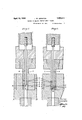
- Figure 1 is a longitudinal sectional view through the die and punches used tofcarry this invention into effect showing the billet in the die with the punches in position ready to commence the extrusion of thel metal of said billet.
- Figure 2 is a view similar to Figure 1 showing -the extrusion punch slightly ad- "vanced and the metal of the billet partly extruded through the throat of the die.
- Figure 3 is a view similar to Figuresl 1 and 2 showing the main punch advanced to substantially its maximum position with the pilot punch shown in its altered relation-in 'respect to the throatof the die to create a difference in diameter in the interior of the'v extruded member.
- FIG. 4 is a perspective view of the'completed blank.
- Figure 6 is a sectional detail of the machined valvebody.
- the heated billet is inserted into the die 8 whichis rovided with a ring 4 having an 55 upper sur ace 5 converging to a throat 6.
- a punch 7 is. inserted into the diel 3 to engagethe upper surface ofthe billet 1 and asmall pilot punch 8 extending through the punch 7 projects beyond the inner end there- 60 vof and extends through the perforation -2 of -the billet.
- the ehd of the pilot punch 8 is taperedl to a reduced end portion 9 which is of the diameter which it is desired'to make the interior 5 ofthe valve blank fora portion of its length.
- the two punches are loperated by' suitable mechanisms to move inwardly into the-dieI and when the main punch 7 engages the billet the inner reduced end 9 ofthe pilot punch 7 8 is disposed within thelthroat of the die.
- the continued movement of the punch 7 causes the metal of the billet to flow' downwardly and thev converging surface 5 directs the metal into the throat and it flows past the reduced end 9 of the pilot punch forming a tubular structure 10 with anoutside diameter conforming to the internal diameter and shape of the ring 4- and an internal diameter corresponding with the end 9 of theo pilot punch,
- the progression of the inner or pilot punch is regulated in accordance with the required] internal measurement of the blank and said inner punch moves inwardly until its larger diameter moves into the 4plane of the throat 6 and the area through which the metal extruded from the billet isthus reduced result-l ing in the interior dimension of the tubular roduct being drawn in a taper to a larger iameter 11.
- the die ring 4 may be shaped with a circular forming throat, or it may be of any other desirable shape to produce an article with a special perimeter ⁇ conformation.
- the die is formed with two parallelly flattened portions which thus form the main body portion 13 of the blank with the fiat sides 14.
- a blank thus produced is of very uniform texture and it is perforated from end to end which enables the insertion of reaming and other finishing tools without the necessity of previous boring and the diameters of the interior may be so arranged that the minimum of metal is required to be removed in the finishing operations, so also the'exterior is produced of diameters which correspond closely to the finished diameter.
- the billets may be made up to any desired formulae in accordance with the article to be produced and advantage maybe taken of the use of scrap metal to a considerable extent, as it is all melted down and formed int-o billets instead of using expensive bar stock as is at present the practice.
- the operation is extremely simple but is lvery fast as the dies are Lmounted in a stamping type of press where the action rs quick.
- the mechanism for operating the punches is not herein shown as it is notdeemed necessary, nor is any particular device shown for removing the 4completed blanks from the die.
- a method of making tubular metal blanks of successive stepped dimensions consisting in applying an extruding pressure to a quantity of metal to flow the same through a forming passage and successively altering the eHective cross-sectional area of said forming passage to effect corresponding successive changes in the cross-sectional dimensions of the extruded blank.
- a method of making tubular metal blanks of stepped internal dimensions consistlng in applying an extruding pressure to a confined quantity of extrudable metal to ex. trude the same through a forming passage and advancing a punch of stepped cross-section through the forming passage to successively alter the dimensions of lthe latter, thereby producing corresponding successive changes in the internal dimensions of the extruded blank.
Landscapes
- Engineering & Computer Science (AREA)
- Mechanical Engineering (AREA)
- Forging (AREA)
Description
J. w. LElGl-rroN 1,854,411
Filed March 16, 1951 `2 Sheets-Sheet `2 Il? lfenfar J/m W. eig/:fon f@ ab METHOD OF MAKING TUBULAR METAL BLANKS April '19, 1932.
Patented Apr. '149,- 1932 PATENT OFFICE JOHN WYCLIFFE LEIGHTON, F PORT H-URON, MICHIGAN v F i 'METHOD 0F MAKING. TUBULAR METAL IBILAN'KS,v
'Application led March 16v, 1931.' Serial No. 522,929.V
-The princi al object of this invention is 'to form bla thereby reducing the machine operations for 6 completing the body and effecting a remarkable saving of labor and material.-
A further and important object is to'ldef vise a method `whereby such articles as tire valve bodies may be formedfrom bulk metal rather thanfrom pre-manufactured rod.
The principal feature of the inventionconsistsin the novel method of forminor a tubular blank with a stem ofa diameter smaller than the base and o f a desired cross sec- 15 tional shape.
In the accompanying drawings, Figure 1 is a longitudinal sectional view through the die and punches used tofcarry this invention into effect showing the billet in the die with the punches in position ready to commence the extrusion of thel metal of said billet. l i l v Figure 2 is a view similar to Figure 1 showing -the extrusion punch slightly ad- "vanced and the metal of the billet partly extruded through the throat of the die.
Figure 3 is a view similar to Figuresl 1 and 2 showing the main punch advanced to substantially its maximum position with the pilot punch shown in its altered relation-in 'respect to the throatof the die to create a difference in diameter in the interior of the'v extruded member. v
- Figure 4 is a perspective view of the'completed blank. a
- Figure 5 is an end elevational View of the completed blank.
Figure 6 is a sectional detail of the machined valvebody.
It has/been the custom in the manufacture of bodies fortire valves to use rolled rod stock and to turn down'the material to the required diameters and otherwise machine the metal to the required shape andv sizes and to bore and ream the interior. j
It is the purpose of this invention/to greatly simplify the manufacture of such articles and in the carrying of this process into effect a cylindrical billet 1, preferably formed with an Aaxial perforation 2 is first heated s, particularly adaptable for tire valve bodies by a method of extrusion,l
metal of a lesser to a temperature which will enable the metals to flow freely upon the application of the pressure of a punch thereto. The heated billet is inserted into the die 8 whichis rovided with a ring 4 having an 55 upper sur ace 5 converging to a throat 6.
A punch 7 is. inserted into the diel 3 to engagethe upper surface ofthe billet 1 and asmall pilot punch 8 extending through the punch 7 projects beyond the inner end there- 60 vof and extends through the perforation -2 of -the billet.
The ehd of the pilot punch 8 is taperedl to a reduced end portion 9 which is of the diameter which it is desired'to make the interior 5 ofthe valve blank fora portion of its length.
The two punches are loperated by' suitable mechanisms to move inwardly into the-dieI and when the main punch 7 engages the billet the inner reduced end 9 ofthe pilot punch 7 8 is disposed within thelthroat of the die.
The continued movement of the punch 7 causes the metal of the billet to flow' downwardly and thev converging surface 5 directs the metal into the throat and it flows past the reduced end 9 of the pilot punch forming a tubular structure 10 with anoutside diameter conforming to the internal diameter and shape of the ring 4- and an internal diameter corresponding with the end 9 of theo pilot punch,
It will be readily understood thatI th/e downward movement of the punch 7 acting `against the larger area of the `billet will for a certain movement of the punch displace suflicient metal at the inward end of the bilv let to flow through the die to forma length of y 'tubular material of much greater length than the length of movement of the punch, that is to say. a short movement of the punch produees .a 'considerable length of 'extruded diameter than that of the billet.
The progression of the inner or pilot punch is regulated in accordance with the required] internal measurement of the blank and said inner punch moves inwardly until its larger diameter moves into the 4plane of the throat 6 and the area through which the metal extruded from the billet isthus reduced result-l ing in the interior dimension of the tubular roduct being drawn in a taper to a larger iameter 11.
The movement of the punches continues until the desired length of blank has been formed, a flange 12 being left at the inward end of substantially the same diameter required for the flange of the valve body.
The die ring 4 may be shaped with a circular forming throat, or it may be of any other desirable shape to produce an article with a special perimeter` conformation.
In the instance illustrated, where a valve body blank is produced the die is formed with two parallelly flattened portions which thus form the main body portion 13 of the blank with the fiat sides 14.
A blank thus produced is of very uniform texture and it is perforated from end to end which enables the insertion of reaming and other finishing tools without the necessity of previous boring and the diameters of the interior may be so arranged that the minimum of metal is required to be removed in the finishing operations, so also the'exterior is produced of diameters which correspond closely to the finished diameter.
It will be readily appreciated by those skilled in the art of machining metal that the tools will require the very minimum of time for completing the finished surfaces. They will also have their actual cutting period reduced to the minimum so that not only is a great saving of time effected but the actual wear upon the tools is materially lessened.
It will be understood that the billets may be made up to any desired formulae in accordance with the article to be produced and advantage maybe taken of the use of scrap metal to a considerable extent, as it is all melted down and formed int-o billets instead of using expensive bar stock as is at present the practice.
The operation is extremely simple but is lvery fast as the dies are Lmounted in a stamping type of press where the action rs quick. The mechanism for operating the punches is not herein shown as it is notdeemed necessary, nor is any particular device shown for removing the 4completed blanks from the die.
f thereof into the plane of the throat, then applyingpressure to the billet extruding the `then projecting a pilot punch through the perforation of the billet until its inner end is in the plane of the throat of the die, then moving a punch inwardly against the billet to flow the metal thereof through the throat around said central punch, then moving the central punch further into the throat to effect `a reduction of the cross sectional area of the metal fiowing therethrough, and thereby forming a blank with a central passage of varying diameter, the extruding punch being arrested to retain a flange upon the end of the metal blank.
3. A method of making tubular metal blanks of successive stepped dimensions consisting in applying an extruding pressure to a quantity of metal to flow the same through a forming passage and successively altering the eHective cross-sectional area of said forming passage to effect corresponding successive changes in the cross-sectional dimensions of the extruded blank.
4. A method of making tubular metal blanks of stepped internal dimensions consistlng in applying an extruding pressure to a confined quantity of extrudable metal to ex. trude the same through a forming passage and advancing a punch of stepped cross-section through the forming passage to successively alter the dimensions of lthe latter, thereby producing corresponding successive changes in the internal dimensions of the extruded blank.
A method according to claim 4 in which said stepped punch is advanced to gradually alter the size of the forming passage during the extrusion, producing a gradual change in the internal dimensions of the extruded blank between theI successive stepped portions thereof producing a connecting portion between the respective stepped portions having a tapered effect on the inner Wall.
JOHN WYCLIFFE LEIGHTON.
metal through said throat around the reduced r end of the punch to form a tube, then during the extruding movement moving the inner punch to bring its larger diameter into the l (la
Priority Applications (1)
| Application Number | Priority Date | Filing Date | Title |
|---|---|---|---|
| US522929A US1854411A (en) | 1931-03-16 | 1931-03-16 | Method of making tubular metal blanks |
Applications Claiming Priority (1)
| Application Number | Priority Date | Filing Date | Title |
|---|---|---|---|
| US522929A US1854411A (en) | 1931-03-16 | 1931-03-16 | Method of making tubular metal blanks |
Publications (1)
| Publication Number | Publication Date |
|---|---|
| US1854411A true US1854411A (en) | 1932-04-19 |
Family
ID=24082950
Family Applications (1)
| Application Number | Title | Priority Date | Filing Date |
|---|---|---|---|
| US522929A Expired - Lifetime US1854411A (en) | 1931-03-16 | 1931-03-16 | Method of making tubular metal blanks |
Country Status (1)
| Country | Link |
|---|---|
| US (1) | US1854411A (en) |
Cited By (12)
| Publication number | Priority date | Publication date | Assignee | Title |
|---|---|---|---|---|
| US2778493A (en) * | 1951-12-31 | 1957-01-22 | Kreidler Alfred | Apparatus for the production of tubular bodies with variable cross-section |
| US2903130A (en) * | 1954-11-19 | 1959-09-08 | Baldwin Lima Hamilton Corp | Method of extruding tubes |
| US2942728A (en) * | 1957-10-22 | 1960-06-28 | Harvey Machine Co Inc | Method of and apparatus for making extruded tubing |
| DE1125261B (en) * | 1957-12-05 | 1962-03-08 | Aluminium Ind Ag | Process for the production of pipe sleeves with an outer end flange |
| US3040883A (en) * | 1959-05-29 | 1962-06-26 | Felten & Guilleaume Carlswerk | Press for extruding tubing and the like while avoiding contractions |
| US3116834A (en) * | 1960-12-22 | 1964-01-07 | Baldwin Lima Hamilton Corp | Extrusion of metal tubing |
| US3122823A (en) * | 1959-04-22 | 1964-03-03 | Thompson Ramo Wooldridge Inc | Turbine wheel and method of making same |
| US3176494A (en) * | 1959-04-27 | 1965-04-06 | Reynolds Metals Co | Extrusion press |
| US3178920A (en) * | 1962-05-22 | 1965-04-20 | Cefilac | Method of hot extrusion of hollow sections |
| US3362208A (en) * | 1965-01-07 | 1968-01-09 | Reynolds Metals Co | Extruding metal members of varying wall thickness |
| US4592224A (en) * | 1982-12-24 | 1986-06-03 | Swiss Aluminium Ltd. | Process and device for extruding a hollow section |
| US4768369A (en) * | 1987-11-13 | 1988-09-06 | Johnson Russell H | Method of forming a pipe fitting |
-
1931
- 1931-03-16 US US522929A patent/US1854411A/en not_active Expired - Lifetime
Cited By (12)
| Publication number | Priority date | Publication date | Assignee | Title |
|---|---|---|---|---|
| US2778493A (en) * | 1951-12-31 | 1957-01-22 | Kreidler Alfred | Apparatus for the production of tubular bodies with variable cross-section |
| US2903130A (en) * | 1954-11-19 | 1959-09-08 | Baldwin Lima Hamilton Corp | Method of extruding tubes |
| US2942728A (en) * | 1957-10-22 | 1960-06-28 | Harvey Machine Co Inc | Method of and apparatus for making extruded tubing |
| DE1125261B (en) * | 1957-12-05 | 1962-03-08 | Aluminium Ind Ag | Process for the production of pipe sleeves with an outer end flange |
| US3122823A (en) * | 1959-04-22 | 1964-03-03 | Thompson Ramo Wooldridge Inc | Turbine wheel and method of making same |
| US3176494A (en) * | 1959-04-27 | 1965-04-06 | Reynolds Metals Co | Extrusion press |
| US3040883A (en) * | 1959-05-29 | 1962-06-26 | Felten & Guilleaume Carlswerk | Press for extruding tubing and the like while avoiding contractions |
| US3116834A (en) * | 1960-12-22 | 1964-01-07 | Baldwin Lima Hamilton Corp | Extrusion of metal tubing |
| US3178920A (en) * | 1962-05-22 | 1965-04-20 | Cefilac | Method of hot extrusion of hollow sections |
| US3362208A (en) * | 1965-01-07 | 1968-01-09 | Reynolds Metals Co | Extruding metal members of varying wall thickness |
| US4592224A (en) * | 1982-12-24 | 1986-06-03 | Swiss Aluminium Ltd. | Process and device for extruding a hollow section |
| US4768369A (en) * | 1987-11-13 | 1988-09-06 | Johnson Russell H | Method of forming a pipe fitting |
Similar Documents
| Publication | Publication Date | Title |
|---|---|---|
| US1854411A (en) | Method of making tubular metal blanks | |
| CN106903251B (en) | Production Technology of Cold Heading of Metal Parts with Through Hole Long Shank Sleeve | |
| US2392175A (en) | Process of making hollow valves | |
| KR20220110154A (en) | Long cartridge case | |
| US1819254A (en) | Art of extruding cold materials | |
| US2405298A (en) | Twist drill | |
| US2904173A (en) | Plunger and die for indirect extrusion | |
| US3036366A (en) | Method of making ball studs | |
| US2030290A (en) | Method and apparatus for making headed blanks and resultant article | |
| US2080850A (en) | Manufacture of nuts | |
| CN103978061B (en) | Slender thick-wall variable cross-section inner hole hydraulic extrusion device and method | |
| US1373726A (en) | Method of and die for producing forgings | |
| US2077519A (en) | Method of making metal articles | |
| US3561242A (en) | Process for forming bottomed tubular members from metal blanks | |
| US3283556A (en) | Apparatus for forming articles | |
| US2942728A (en) | Method of and apparatus for making extruded tubing | |
| US2565665A (en) | Screw and method of making same | |
| US2348179A (en) | Method and apparatus for the production of cylindrical metal articles | |
| US2930483A (en) | Cold shaping of steel | |
| US1430004A (en) | Method of making socket-wrench heads | |
| US2500890A (en) | Metal working method and mechanism | |
| US3413945A (en) | Process for manufacturing points for ball-point pens | |
| US2113172A (en) | Manufacture of headed blanks | |
| US2064918A (en) | Bolt and the like and process of making | |
| US1599572A (en) | Art of producing articles by extrusion |