US1854401A - Ignition coil - Google Patents
Ignition coil Download PDFInfo
- Publication number
- US1854401A US1854401A US568979A US56897931A US1854401A US 1854401 A US1854401 A US 1854401A US 568979 A US568979 A US 568979A US 56897931 A US56897931 A US 56897931A US 1854401 A US1854401 A US 1854401A
- Authority
- US
- United States
- Prior art keywords
- conductor
- sleeve
- socket
- wires
- ignition coil
- Prior art date
- Legal status (The legal status is an assumption and is not a legal conclusion. Google has not performed a legal analysis and makes no representation as to the accuracy of the status listed.)
- Expired - Lifetime
Links
- 239000004020 conductor Substances 0.000 description 26
- 239000002184 metal Substances 0.000 description 14
- 229910052751 metal Inorganic materials 0.000 description 14
- 238000004804 winding Methods 0.000 description 12
- XEEYBQQBJWHFJM-UHFFFAOYSA-N Iron Chemical compound [Fe] XEEYBQQBJWHFJM-UHFFFAOYSA-N 0.000 description 2
- 238000009413 insulation Methods 0.000 description 2
- 238000002485 combustion reaction Methods 0.000 description 1
- 238000006073 displacement reaction Methods 0.000 description 1
- OYFJQPXVCSSHAI-QFPUQLAESA-N enalapril maleate Chemical compound OC(=O)\C=C/C(O)=O.C([C@@H](C(=O)OCC)N[C@@H](C)C(=O)N1[C@@H](CCC1)C(O)=O)CC1=CC=CC=C1 OYFJQPXVCSSHAI-QFPUQLAESA-N 0.000 description 1
- 239000000945 filler Substances 0.000 description 1
- 229910052742 iron Inorganic materials 0.000 description 1
- 239000000463 material Substances 0.000 description 1
Images
Classifications
-
- H—ELECTRICITY
- H01—ELECTRIC ELEMENTS
- H01F—MAGNETS; INDUCTANCES; TRANSFORMERS; SELECTION OF MATERIALS FOR THEIR MAGNETIC PROPERTIES
- H01F38/00—Adaptations of transformers or inductances for specific applications or functions
- H01F38/12—Ignition, e.g. for IC engines
Definitions
- This invention relates to ignition coils and more particularly to coils used in the ignition systems ofinternal combustion engines. It is one of the objects of the present invention to provide improved means for connecting the secondary or high tension terminals of the coil with an insulated flexible stranded wire conductor.
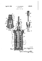
- Fig.1 is a longitudinal sectional view of a coil embodying the present invention.
- Fig. 2 is a fragmentary view of the high tension terminal connector thereof and is drawn on a larger scale than Fig. 1.
- Fig. 3 is a View showing the insulated flexible stranded wire conductor in disassembled relation with respect to the connector plug to which it is attached.
- the ignition coil to which the present invention is applied comprises a case closed by a nonconducting cap 21 which carries terminals 22 and 23 connected with leads 24 and 25 respectively of a primary winding 26.
- the primary winding 26 surrounds a secondary winding 27 wound upon a core 28.
- the outer end of the secondary winding 27 is attached to the primary lead 25.
- the inner end (not shown) of the secondary winding 27 is grounded upon a magnetic core 29 comprising a bundle of iron wires.
- the outer magnetic circuit is provided by convolutions of magnetizable sheet material 30.
- the vacant spaces within the case 20 are occupied by a filler of pitch or wax 31 which serves to insulate the parts and to prevent displacement thereof relative to the case 20.
- the cover 21 has an upwardly projecting socket in which is embedded a metallicinsert 41 having a threaded hole 42 and a plain hole 43 through which extends a nail or pin 44 the lower end of which is forced into the bundle of wires forming the core 30, thus providing an electrical connection between the inside lead of the secondary winding 27 and the socket insert 41.
- the threaded hole 42 in the socket insert 41 receives the threaded portion 45 of a metal sleeve 46 around which is moulded a nonconducting sleeve 47 having a knurled portion 48 to facilitate turning the sleeve 47 when screwing the metal sleeve 46 to the socket 41.
- the sleeve 47 provides a circular bore 49 which receives the unstripped portion of a conductor 50 comprising stranded flexible wires 51 covered by insulation 52.
- the circular bore 53 within the metal sleeve 46 receives the bared portion of the wires 51 and the bore 49 of the nonconducting sleeve 47 receives the insulation 52.
- the bared portion 51 is slightly greater in length than the metal sleeve 46 so that, when the conductor 50 and the sleeve 46 are assembled as shown in Fig. 1, the lower ends of the wires 51 will project below the lower end of the sleeve 46.
- the lower ends of the stranded wires 51 are frayed out and bent over at 51a in Figs. 1 and 2 but are not attached to the sleeve 46. Since the conductor 50 is not connected to the-sleeve 46 it does not turn while screwing the sleeve 46 into the socket 41.
- An ignition coil comprising, in combiductoragainst the conductor at the bottom of nation, a tubular case, windings within the the threaded hole.
- a cover for the case provided with a nonconducting socket a metal insert within the socket and having a threaded hole, a metal pin passing through the insert and projecting into the central core, and means for connecting an insulated stranded wire conductor with the threaded socket insert and comprising a plug having a metallic tubular sleeve threadedly engageable with the socket insert, a bared portion of the conductor passing through the sleeve and the wires of the conductor being bent over against the end of the metal sleeve, said plug having a nonconducting sleeve providing a handle for the metal sleeve and providing a socket for receiving an insulated portion of the conductor, the screwing of the plug while attached to the conductor, into the socket insert clamping the wires of the conductor against the head of the metal pin.
- An ignition coil comprising, in combination, a tubular case, windings within the case, a cover for the case provided with a nonconducting socket, a metal insert within the socket and having a threaded hole, means connecting the metal insert with one of the coil windings, and means for connecting an insulated stranded Wire conductor.
- the threaded socket insert and comprising a plug having a metallic tubular sleeve threadedly engageable with the socket insert, a bared portion of the conductor passing through the sleeve and the wires of the conductor being bent over against the end of the metal sleeve, said plug having a nonconducting sleeve providing a handle for the metal sleeve and providing a socket for receiving an insulated portion of the conductor, the screwing of the plug while attached to the conductor, into the socket insert clamping the wires of the conductor against the closed end wall of the metal insert.
- An ignition coil comprising, in combination, a tubular case, windings within the case, a cover for the case, said cover including means providing a threaded hole, a conductor at the bottom of the threaded hole and connected with one of the windings, and means for connecting an insulated stranded wire conductor with the conductor in the threaded hole, and comprising an externally threaded tubular member which screws into the threaded hole of the cover, a bared portion of the'wire conductor passing loosely through the member and the wires of the conductor being bent over against the end of the member, said member providing a socket for receiving an insulated portion of the conductor, the screwing of the member into the threaded part of the cover, while attached to the wire, clamping the wires of the wire con-
Landscapes
- Engineering & Computer Science (AREA)
- Power Engineering (AREA)
- Ignition Installations For Internal Combustion Engines (AREA)
Description
pril 19, 1932.
J. T. FITZS IMMONS IGNITION COIL Filed Oct. 15, 1951 Patented Apr. '19, 1932 UNITED STATES PATENT OFFICE JOHN T. FITZSIMMON S, F ANDERSON, INDIANA, ASSIGNOR TO DELCO-REMY CORPORA- TION, OF ANDERSON, EN DIANA, A CORPORATION OF DELAWARE IGNITION COIL Application filed October 15, 1931. Serial No. 568,979.
This invention relates to ignition coils and more particularly to coils used in the ignition systems ofinternal combustion engines. It is one of the objects of the present invention to provide improved means for connecting the secondary or high tension terminals of the coil with an insulated flexible stranded wire conductor.
Further objects and advantages of the pres ent invention will be apparent from the following description, reference being had to the accompanying drawings wherein a preferred embodiment-of one form of the present invention is clearly shown.
In the drawings:
Fig.1 is a longitudinal sectional view of a coil embodying the present invention.
Fig. 2 is a fragmentary view of the high tension terminal connector thereof and is drawn on a larger scale than Fig. 1.
Fig. 3 is a View showing the insulated flexible stranded wire conductor in disassembled relation with respect to the connector plug to which it is attached.
The ignition coil to which the present invention is applied comprises a case closed by a nonconducting cap 21 which carries terminals 22 and 23 connected with leads 24 and 25 respectively of a primary winding 26. The primary winding 26 surrounds a secondary winding 27 wound upon a core 28. The outer end of the secondary winding 27 is attached to the primary lead 25. The inner end (not shown) of the secondary winding 27 is grounded upon a magnetic core 29 comprising a bundle of iron wires. The outer magnetic circuit is provided by convolutions of magnetizable sheet material 30. The vacant spaces within the case 20 are occupied by a filler of pitch or wax 31 which serves to insulate the parts and to prevent displacement thereof relative to the case 20.
The cover 21 has an upwardly projecting socket in which is embedded a metallicinsert 41 having a threaded hole 42 and a plain hole 43 through which extends a nail or pin 44 the lower end of which is forced into the bundle of wires forming the core 30, thus providing an electrical connection between the inside lead of the secondary winding 27 and the socket insert 41.
The threaded hole 42 in the socket insert 41 receives the threaded portion 45 of a metal sleeve 46 around which is moulded a nonconducting sleeve 47 having a knurled portion 48 to facilitate turning the sleeve 47 when screwing the metal sleeve 46 to the socket 41. The sleeve 47 provides a circular bore 49 which receives the unstripped portion of a conductor 50 comprising stranded flexible wires 51 covered by insulation 52. The circular bore 53 within the metal sleeve 46 receives the bared portion of the wires 51 and the bore 49 of the nonconducting sleeve 47 receives the insulation 52. The bared portion 51 is slightly greater in length than the metal sleeve 46 so that, when the conductor 50 and the sleeve 46 are assembled as shown in Fig. 1, the lower ends of the wires 51 will project below the lower end of the sleeve 46. Before attaching the plug comprising sleeves 46 and 47 to the ignition coil cover 21, the lower ends of the stranded wires 51 are frayed out and bent over at 51a in Figs. 1 and 2 but are not attached to the sleeve 46. Since the conductor 50 is not connected to the-sleeve 46 it does not turn while screwing the sleeve 46 into the socket 41. This facilitates the connection of the conductor 50 with the coil terminal since the conductor 50 is not twisted while turning the sleeve 46. When the sleeve 46 is screwed into the socket insert 41 as far as it can be turned, the ends 51a of the stranded wires 51 are clamped between the lower end of the sleeve 46 and the bottom wall of the socket insert 41 and the head of the pin or nail 44' thus insuring a good electrical contact between the core 30 and the wire 51. Since the wires 51a are pinched or tightly clamped in position, they serve to resist the accidental unscrewing of the sleeve 46 from the insert 41.
While the form of embodiment of the present invention as herein disclosed, constitutes a preferred form, it is to be understood that other forms might be adopted, all coming within the scope of the claims which follow.
What is claimed is as follows:
1. An ignition coil comprising, in combiductoragainst the conductor at the bottom of nation, a tubular case, windings within the the threaded hole.
case, a core centrally located within the wind- In testimony whereof I hereto aifix my sigings and electrically connected with one of nature.
the windings, a cover for the case provided with a nonconducting socket, a metal insert within the socket and having a threaded hole, a metal pin passing through the insert and projecting into the central core, and means for connecting an insulated stranded wire conductor with the threaded socket insert and comprising a plug having a metallic tubular sleeve threadedly engageable with the socket insert, a bared portion of the conductor passing through the sleeve and the wires of the conductor being bent over against the end of the metal sleeve, said plug having a nonconducting sleeve providing a handle for the metal sleeve and providing a socket for receiving an insulated portion of the conductor, the screwing of the plug while attached to the conductor, into the socket insert clamping the wires of the conductor against the head of the metal pin.
2. An ignition coil comprising, in combination, a tubular case, windings within the case, a cover for the case provided with a nonconducting socket, a metal insert within the socket and having a threaded hole, means connecting the metal insert with one of the coil windings, and means for connecting an insulated stranded Wire conductor.with the threaded socket insert and comprising a plug having a metallic tubular sleeve threadedly engageable with the socket insert, a bared portion of the conductor passing through the sleeve and the wires of the conductor being bent over against the end of the metal sleeve, said plug having a nonconducting sleeve providing a handle for the metal sleeve and providing a socket for receiving an insulated portion of the conductor, the screwing of the plug while attached to the conductor, into the socket insert clamping the wires of the conductor against the closed end wall of the metal insert.
3. An ignition coil comprising, in combination, a tubular case, windings within the case, a cover for the case, said cover including means providing a threaded hole, a conductor at the bottom of the threaded hole and connected with one of the windings, and means for connecting an insulated stranded wire conductor with the conductor in the threaded hole, and comprising an externally threaded tubular member which screws into the threaded hole of the cover, a bared portion of the'wire conductor passing loosely through the member and the wires of the conductor being bent over against the end of the member, said member providing a socket for receiving an insulated portion of the conductor, the screwing of the member into the threaded part of the cover, while attached to the wire, clamping the wires of the wire con-
Priority Applications (1)
| Application Number | Priority Date | Filing Date | Title |
|---|---|---|---|
| US568979A US1854401A (en) | 1931-10-15 | 1931-10-15 | Ignition coil |
Applications Claiming Priority (1)
| Application Number | Priority Date | Filing Date | Title |
|---|---|---|---|
| US568979A US1854401A (en) | 1931-10-15 | 1931-10-15 | Ignition coil |
Publications (1)
| Publication Number | Publication Date |
|---|---|
| US1854401A true US1854401A (en) | 1932-04-19 |
Family
ID=24273570
Family Applications (1)
| Application Number | Title | Priority Date | Filing Date |
|---|---|---|---|
| US568979A Expired - Lifetime US1854401A (en) | 1931-10-15 | 1931-10-15 | Ignition coil |
Country Status (1)
| Country | Link |
|---|---|
| US (1) | US1854401A (en) |
Cited By (5)
| Publication number | Priority date | Publication date | Assignee | Title |
|---|---|---|---|---|
| US2628342A (en) * | 1945-09-25 | 1953-02-10 | Western Union Telegraph Co | Inductance coil |
| US2806998A (en) * | 1951-02-08 | 1957-09-17 | Citroen Sa Andre | Ignition coils for internal combustion engines |
| US3236937A (en) * | 1963-04-29 | 1966-02-22 | Briggs & Stratton Corp | Connector means and receptacle for connecting high tension lead to ignition coil |
| US3949338A (en) * | 1974-06-10 | 1976-04-06 | R. E. Phelon Company, Inc. | Ignition coil |
| US20060273608A1 (en) * | 2005-05-11 | 2006-12-07 | Masami Shinsho | Straddle-type vehicle |
-
1931
- 1931-10-15 US US568979A patent/US1854401A/en not_active Expired - Lifetime
Cited By (6)
| Publication number | Priority date | Publication date | Assignee | Title |
|---|---|---|---|---|
| US2628342A (en) * | 1945-09-25 | 1953-02-10 | Western Union Telegraph Co | Inductance coil |
| US2806998A (en) * | 1951-02-08 | 1957-09-17 | Citroen Sa Andre | Ignition coils for internal combustion engines |
| US3236937A (en) * | 1963-04-29 | 1966-02-22 | Briggs & Stratton Corp | Connector means and receptacle for connecting high tension lead to ignition coil |
| US3949338A (en) * | 1974-06-10 | 1976-04-06 | R. E. Phelon Company, Inc. | Ignition coil |
| US20060273608A1 (en) * | 2005-05-11 | 2006-12-07 | Masami Shinsho | Straddle-type vehicle |
| US8091673B2 (en) * | 2005-05-11 | 2012-01-10 | Yamaha Hatsudoki Kabushiki Kaisha | Straddle type vehicle |
Similar Documents
| Publication | Publication Date | Title |
|---|---|---|
| US5357233A (en) | Ignition apparatus for internal combustion engine | |
| KR910017064A (en) | Ignition Coil for Internal Combustion Engines | |
| US4400600A (en) | Gas spring arrangement operating as an electrical connection | |
| US20080274632A1 (en) | Spark Plug Terminal Connection Apparatuses and Methods | |
| JP2008053204A (en) | Ignition coil | |
| US9897064B2 (en) | Ignition coil for internal combustion engine | |
| US1854401A (en) | Ignition coil | |
| US6836203B2 (en) | Ignition coil for internal combustion engine | |
| US3054027A (en) | Winding terminal | |
| US6422225B1 (en) | Ignition coil and method of making | |
| US2653992A (en) | Terminal construction for electric coil forms | |
| US7252078B2 (en) | Spark plug connector | |
| US1641374A (en) | Induction coil | |
| US1505531A (en) | Flexible terminal for ignition wires | |
| US1883905A (en) | Ignition coil | |
| US2790962A (en) | Terminal assembly | |
| US2515897A (en) | Spark plug cable | |
| US20060211292A1 (en) | Electrical contact between thin varnished wires of the secondary winding of an ignition coil | |
| US1729492A (en) | Coil | |
| JPS6225865Y2 (en) | ||
| US1400354A (en) | Electric heating-plug | |
| US2143110A (en) | Connecter | |
| JPH06325954A (en) | Ignition coil for internal combustion engine, and its manufacture | |
| US2114750A (en) | Radio shielding spark plug connection | |
| US2090501A (en) | Weatherproof socket |