US1854344A - Well point attachment - Google Patents
Well point attachment Download PDFInfo
- Publication number
- US1854344A US1854344A US464659A US46465930A US1854344A US 1854344 A US1854344 A US 1854344A US 464659 A US464659 A US 464659A US 46465930 A US46465930 A US 46465930A US 1854344 A US1854344 A US 1854344A
- Authority
- US
- United States
- Prior art keywords
- hole
- well
- water
- soil
- well point
- Prior art date
- Legal status (The legal status is an assumption and is not a legal conclusion. Google has not performed a legal analysis and makes no representation as to the accuracy of the status listed.)
- Expired - Lifetime
Links
Images
Classifications
-
- E—FIXED CONSTRUCTIONS
- E21—EARTH OR ROCK DRILLING; MINING
- E21B—EARTH OR ROCK DRILLING; OBTAINING OIL, GAS, WATER, SOLUBLE OR MELTABLE MATERIALS OR A SLURRY OF MINERALS FROM WELLS
- E21B7/00—Special methods or apparatus for drilling
- E21B7/18—Drilling by liquid or gas jets, with or without entrained pellets
Definitions
- This invention relates to an attachment for well points of the class set forth in my Patent No. 1,729,790 of October l, 1929 in that it involves the use of a pipe having one end (its upper end) connected to the source of water supply preferably under pressure and its other or lower end provided with a jetting nozzle through which the water passing through the pipe is projected for jetting a holein the soil and thereby to facilitate the descend of the well point under itsown weight aided by external pressure and more or less lateral and angular oscillatory movements thereof.
- These well points are used primarily for draining water-containing soil and may serve the double purpose of making holes in the soil to the required depth for removing the moisture content by forcing water therethrough into the soil to aid in the descent ofthe well point and also for removing the water content from the soil by simply attaching the same well point to an eX- ternal suction pump, although it is evident that as the hole is made by one well point by jetting the water therethrough, it may be removed and replaced by another well point and connected to a suction device for withdrawing the water from the soil through the same hole.
- the main object therefore of the present invention Ais to overcome these objections by providing the etting nozzle of the well point with simple and eilicient means for automatically enlarging the hole beyond the outer sur-race of the well point as the latter descends into the soil 'and at thesame time to permit the hole-enlarging means to be withdrawn at will from the soil after the well point has been elevated sufficiently to disengage it from the cage.
- l have sought to provide a hole-enlarging attachment capable of being easily and quickly applied to and removed from the j etting nozzle so that when in operative position, it will enlarge the hole beyond therouter surface of the well point without in any way obstructing the 'free 'flow of the jetting water into the hole in advance of the discharge nozzle.
- nozzles are usually tapered toward their lower ends and one of the specic objects is to provide an open-work articulate cap of frusto-conical form adapted to embrace thelowerl tapered end of ythe nozzle while the well point is beingrr used for etting purposes and also while withdrawing the @water from the soil with the assurance that the attachment willI make the hole sufciently large to allow the jetting water and vsoil loosened thereby to be displaced upwardly to the surface of the ground as long as the jetting operation continues, and also to permit the water at all levels from the bottom lof the hole to the Asurface of the ⁇ ground to pass to the bottom ofthe hole-from which it can be readily removed by suction.
- a further object is to provide simple means for tightening and releasing the cage upon and from the well point.
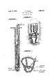
- Figure 1Y is an elevation, partly broken away, of a well point equipped with my improved attachment showing also the hole in the soil made by the well point during its descent.
- Figure 2 is an enlarged sectional view of the lower end of the well point together with my improved attachment thereon, and adapted to be used both for jetting the hole in the ground under water pressure and also for withdrawing the water from the hole by suction.
- Figure 3 is a perspective view ofthe detached hole-enlarging attachment for Ithe well point in position to be applied thereto.
- the well point per se may be iof .any .desired construction and comprises a pipe l having its upper end provided -w-ith an -eX- tension 2 adapted to be connected to a source of water supply under pressure or to a suitable suction pump not necessary to herein illustrate or describe, the Vlower end of .the pipe being lprovided with a downwardly tapered nozzle 3 through which Vwater may be jetted into the soijl to facilitate the descent of the well point; or when the 'hole is made to the required depth, the water which may seep thereinto may be withdrawn by suction through the pipe to be dischargedat its upper end to any suitable waste reservoir.
- the hole-enlarging attachment forming the subject matter ⁇ of the present invention comprises an inverted frusto-conical openwork cap or cage el adapted to fit more o1" less closely around and upon the periphery of the nozzle 3 toproject outwardly and radially therefrom in such vmanner as to enlarge the opening as zin the soil -A- beyond the outer surface of the well point as the latter ⁇ descends into the soil without in any way obstructing Vthe free etting of the water through the nozzle and into the soi-l and at ,the ⁇ same time affording a free exit of the water ⁇ :and loosenedsoil upwardly around the outside of Ythe well point -to the surface off the ground where jit may be drained off to any suitable repository.
- this open-work cap or V,cage comprises a lower Chain ring 5, an upper ⁇ chain ring vor loop f6, and a plurality of upright chains 7 connecting vthe Vlower chain 5 and upper loop 6, said upright chains being preferably arranged in uniformly spaced relation circumferentially to afford ample clearance for the vupwardly displaced water andloosenedsoil.
- va ring? Through which the other end of the upperchaininay be drawn ⁇ by means of a cord or cable '8 whichis also ,free to pass through the ring 7 and serves asa means for tightening and Yreleasing ⁇ the cage upon .and ⁇ from the periphery of thenozzle when the cap or cage is placed in operative position thereon.
- the cord or cable 8 is of suilicient length to extend upwardly through thehole -a,- in t the soil to the surface thereof and is adapted to be secured at its upper end to the pipe l or to its extension 2 to hold the cap or cage 4C in operative position on the nozzle during the descent of the latter into the ground.
- the cord or cable 8 may lbe released yfrom .its securement ,to the pipe 1 and slacliened suliiciently to allow the cage 4 to collapse or drop to the bottom of the hole -by reason of its .articulate construction aided by its weight so that by slightly raising ,the well point from the collapsed cage, the latter may be withdrawn from the zhole by upward displacement through the medium of the cable 8 for re-use on lanother Well point, if desired.
- the cage l is first placed in operative position around the periphery of and upon the vnozzle 3 and held in this position by at- Vtaching the free end of the cord or cable 8 to the upper portion of the pipe l or its eXtension'2.
- This operation may be .performed while the well point, which is usually of considerable length, is still in a horizontal position within easy reaching distance by the operator when standing upon the surface ofthe soil, after which, the well point with the cage Athereon isplaced in an upright ,position with its lower end resting on the surface of the soil ⁇ at the point where the hole is 4to be formed.
- the water under pressure is then turned into the pipe l and jetted through the Anozzle 3 into-the soil thereby forming a hole of suilicient size to permit the well point to descend under its own weight or Vby external pressure with the assurance that the cage V4 will enlarge the hole during such descent leaving a clear open space around the external surface of the well point for lthe upflow displacement-of the water and loose soil from the bottom ofthe hole, and also permitting the seepage of the water from all levels ofthe surrounding soil to the 'bottom of the hole.
- theupperend of the pipe 1 may be disconnected from the source of water supply and re-connected to al suitable suction pump whereby the water seeping into the 'hole from different levels will fall lto the bottom thereof and then be withdrawn by suction upwardly through the pipe l to be discharged by .the pump to any convenient repository for the waste water.
- the Cable 8 may be slackened to release the cage and allow the latter to free itself from the nozzle 3 and drop to the 'bottom of the hole by its own weight.
- the well point may then be slightly raised l to clear the collapsed cage and to permit the latter to be drawn upwardly through and out of the hole by means of the cable 8 for re-use with another well point to form another enlarged hole in the soil while the water is being Withdrawn by suction from the previousf ly lformed hole.
- eXtra loose sand may be introduced into each hole from the top to assure free seepage and exit of the water into and from the hole around the pipe.
- the cage 4l may be used in connection with any pipe adapted to be projected into the ground for enlarging the hole or well around the pipe and thereby to break up the surrounding water-impervious strata and allow the water in the soil to readily gravitate from different levels to the bottom of the well where it may be ⁇ expeditiously removed by suction through the same pipe or through a replacement thereof.
- the Hexible and collapsible cage 4 illustrated and described is particularly simple, practical and elhcient and may be manufactured and applied to the well point at a comparatively low cost but it is evident that various other types of open-work cages may be used upon the Well point without departing ⁇ from the spirit of this invention.
- a well-point having a nozzle, a collapsible cage composed of chains connected to each other and loosely embracing the periphery of the nozzle, and means attached to the cage and extended upwardly therefrom along the outside of the well-point for releasably holding the cage in operative position during the descent of the well-point linto the soil and for withdrawing the cage from the hole when released from the well-point.
- a chain-cage adapted to embrace the lower end of a well-point, and means connected to said cage and operable at will for tightening and releasing said cage upon and from the well-point.
- a hole-enlarging device for use on the lower end of a pipe adapted to enter the ground, said device comprising an articulated open-work cage adapted to embrace a portion of the pipe and including lower and upper rings, one of which is eXpansible and contractible.
- An inverted frusto-conical cage adapted to embrace the lower end of a well-point and composed of chains, operatively connected together, and means operable at will for contracting the larger end of the cage.
- An attachment for well points comprising an articulated bottom ring, an articulated top ring of greater diameter than the bottom ring, articulated side members connecting said rings, and means for contracting the upper ring upon the periphery of the well point when the attachment is applied thereto.
Landscapes
- Life Sciences & Earth Sciences (AREA)
- Engineering & Computer Science (AREA)
- Geology (AREA)
- Mining & Mineral Resources (AREA)
- Physics & Mathematics (AREA)
- Environmental & Geological Engineering (AREA)
- Fluid Mechanics (AREA)
- General Life Sciences & Earth Sciences (AREA)
- Geochemistry & Mineralogy (AREA)
- Earth Drilling (AREA)
Description
April 19, 1932. 11 F, MOORE WELL POINT ATTACHMENT File'd June 28, 195o Patented pr. 19, 1932 THOMAS IE'. MOORE, OF MORRIS PLAINS, NEW JERSEY A'VV'ELL IPONT ATTACHMENT Application led June 28, 1930. Serial No. 4G4,659.
This invention relates to an attachment for well points of the class set forth in my Patent No. 1,729,790 of October l, 1929 in that it involves the use of a pipe having one end (its upper end) connected to the source of water supply preferably under pressure and its other or lower end provided with a jetting nozzle through which the water passing through the pipe is projected for jetting a holein the soil and thereby to facilitate the descend of the well point under itsown weight aided by external pressure and more or less lateral and angular oscillatory movements thereof. v
These well points are used primarily for draining water-containing soil and may serve the double purpose of making holes in the soil to the required depth for removing the moisture content by forcing water therethrough into the soil to aid in the descent ofthe well point and also for removing the water content from the soil by simply attaching the same well point to an eX- ternal suction pump, although it is evident that as the hole is made by one well point by jetting the water therethrough, it may be removed and replaced by another well point and connected to a suction device for withdrawing the water from the soil through the same hole.
ln the operation of gradually projecting the well point into the soil, it is obvious that it will encounter strata of widely varying porosity and density so that, in some instances, it has been found to be extremely dicult to make the'hole suhciently large to permit the escape of the water and loosened soil upwardly along` the outside of the pipe as the water is jetted into the soil, thereby greatly retarding `the progress of the work.
Furthermore, even though the well point may be projected downwardly to the proper depth and that the jetting of the water through the lower end of the nozzle may form an enlargement of the opening at that particular terminus, it frequently happens that the remaining portions of the opening will be closely filled by the well point thereby obstructing the free flow of the water from superposed levels into the enlargement which,of course, would retard the removal of the water from the superposed levels by suction applied to the upper end of the well point.
The main object therefore of the present invention Ais to overcome these objections by providing the etting nozzle of the well point with simple and eilicient means for automatically enlarging the hole beyond the outer sur-race of the well point as the latter descends into the soil 'and at thesame time to permit the hole-enlarging means to be withdrawn at will from the soil after the well point has been elevated sufficiently to disengage it from the cage.
ln other words, l have sought to provide a hole-enlarging attachment capable of being easily and quickly applied to and removed from the j etting nozzle so that when in operative position, it will enlarge the hole beyond therouter surface of the well point without in any way obstructing the 'free 'flow of the jetting water into the hole in advance of the discharge nozzle.
These nozzles are usually tapered toward their lower ends and one of the specic objects is to provide an open-work articulate cap of frusto-conical form adapted to embrace thelowerl tapered end of ythe nozzle while the well point is beingrr used for etting purposes and also while withdrawing the @water from the soil with the assurance that the attachment willI make the hole sufciently large to allow the jetting water and vsoil loosened thereby to be displaced upwardly to the surface of the ground as long as the jetting operation continues, and also to permit the water at all levels from the bottom lof the hole to the Asurface of the `ground to pass to the bottom ofthe hole-from which it can be readily removed by suction.
A further object is to provide simple means for tightening and releasing the cage upon and from the well point.
Other objects and'uses will be brought ou Iin the following description.
In the drawings Figure 1Y is an elevation, partly broken away, of a well point equipped with my improved attachment showing also the hole in the soil made by the well point during its descent.
Figure 2 is an enlarged sectional view of the lower end of the well point together with my improved attachment thereon, and adapted to be used both for jetting the hole in the ground under water pressure and also for withdrawing the water from the hole by suction.
Figure 3 is a perspective view ofthe detached hole-enlarging attachment for Ithe well point in position to be applied thereto.
The well point per se may be iof .any .desired construction and comprises a pipe l having its upper end provided -w-ith an -eX- tension 2 adapted to be connected to a source of water supply under pressure or to a suitable suction pump not necessary to herein illustrate or describe, the Vlower end of .the pipe being lprovided with a downwardly tapered nozzle 3 through which Vwater may be jetted into the soijl to facilitate the descent of the well point; or when the 'hole is made to the required depth, the water which may seep thereinto may be withdrawn by suction through the pipe to be dischargedat its upper end to any suitable waste reservoir.
The hole-enlarging attachment forming the subject matter `of the present invention comprises an inverted frusto-conical openwork cap or cage el adapted to fit more o1" less closely around and upon the periphery of the nozzle 3 toproject outwardly and radially therefrom in such vmanner as to enlarge the opening as zin the soil -A- beyond the outer surface of the well point as the latter `descends into the soil without in any way obstructing Vthe free etting of the water through the nozzle and into the soi-l and at ,the `same time affording a free exit of the water `:and loosenedsoil upwardly around the outside of Ythe well point -to the surface off the ground where jit may be drained off to any suitable repository.
As illustrated, this open-work cap or V,cage comprises a lower Chain ring 5, an upper `chain ring vor loop f6, and a plurality of upright chains 7 connecting vthe Vlower chain 5 and upper loop 6, said upright chains being preferably arranged in uniformly spaced relation circumferentially to afford ample clearance for the vupwardly displaced water andloosenedsoil.
One end of ithe upper loop 6 is provided with va ring? through which the other end of the upperchaininay be drawn `by means of a cord or cable '8 whichis also ,free to pass through the ring 7 and serves asa means for tightening and Yreleasing `the cage upon .and `from the periphery of thenozzle when the cap or cage is placed in operative position thereon.
The cord or cable 8 is of suilicient length to extend upwardly through thehole -a,- in t the soil to the surface thereof and is adapted to be secured at its upper end to the pipe l or to its extension 2 to hold the cap or cage 4C in operative position on the nozzle during the descent of the latter into the ground. r, when the well point as VV- with the attachment 4 thereon has been sunk to the required depth in the soil, the cord or cable 8 may lbe released yfrom .its securement ,to the pipe 1 and slacliened suliiciently to allow the cage 4 to collapse or drop to the bottom of the hole -by reason of its .articulate construction aided by its weight so that by slightly raising ,the well point from the collapsed cage, the latter may be withdrawn from the zhole by upward displacement through the medium of the cable 8 for re-use on lanother Well point, if desired.
Operation,
JWhen'it isdesired 'to sink a well point 'into the soil, the cage l is first placed in operative position around the periphery of and upon the vnozzle 3 and held in this position by at- Vtaching the free end of the cord or cable 8 to the upper portion of the pipe l or its eXtension'2.
This operation may be .performed while the well point, which is usually of considerable length, is still in a horizontal position within easy reaching distance by the operator when standing upon the surface ofthe soil, after which, the well point with the cage Athereon isplaced in an upright ,position with its lower end resting on the surface of the soil `at the point where the hole is 4to be formed.
The water under pressure is then turned into the pipe l and jetted through the Anozzle 3 into-the soil thereby forming a hole of suilicient size to permit the well point to descend under its own weight or Vby external pressure with the assurance that the cage V4 will enlarge the hole during such descent leaving a clear open space around the external surface of the well point for lthe upflow displacement-of the water and loose soil from the bottom ofthe hole, and also permitting the seepage of the water from all levels ofthe surrounding soil to the 'bottom of the hole.
Vhen the hole has been made to the required depth, theupperend of the pipe 1 may be disconnected from the source of water supply and re-connected to al suitable suction pump whereby the water seeping into the 'hole from different levels will fall lto the bottom thereof and then be withdrawn by suction upwardly through the pipe l to be discharged by .the pump to any convenient repository for the waste water.
Vilhen the well point with the cage d thereon has been sunk in the soil to the required depth, the Cable 8 may be slackened to release the cage and allow the latter to free itself from the nozzle 3 and drop to the 'bottom of the hole by its own weight.
The well point may then be slightly raised l to clear the collapsed cage and to permit the latter to be drawn upwardly through and out of the hole by means of the cable 8 for re-use with another well point to form another enlarged hole in the soil while the water is being Withdrawn by suction from the previousf ly lformed hole.
lt is to be understood however that several similar holes may be made in at different points in the soil by separate well points equipped with the cages t in which case the several pipes may be connected to the same or to different sources of water supply for jetting purposes, or, said pipes could be connected to one or more suction pumps for simultaneously withdrawing the water from the several holes.
lf desired, eXtra loose sand may be introduced into each hole from the top to assure free seepage and exit of the water into and from the hole around the pipe.
That is, the cage 4l may be used in connection with any pipe adapted to be projected into the ground for enlarging the hole or well around the pipe and thereby to break up the surrounding water-impervious strata and allow the water in the soil to readily gravitate from different levels to the bottom of the well where it may be `expeditiously removed by suction through the same pipe or through a replacement thereof.
The Hexible and collapsible cage 4 illustrated and described is particularly simple, practical and elhcient and may be manufactured and applied to the well point at a comparatively low cost but it is evident that various other types of open-work cages may be used upon the Well point without departing` from the spirit of this invention.
I claim:
l. The combination with a well-point having a tapered nozzle on its lower end adapted to enter the soil, of a ring releasably engaging the periphery of the nozzle below its upper end for enlarging the hole around the pipe as the latter is driven into the soil, and means attached to the ring and extended upwardly therefrom along the outside of the well-point for tightening and loosening the ring upon and from the nozzle.
2. The combination with a well-point, of an articulated open-work cage composed of chains connected to each other and embracing the lower end of the well-point.
3. A well-point having a nozzle, a collapsible cage composed of chains connected to each other and loosely embracing the periphery of the nozzle, and means attached to the cage and extended upwardly therefrom along the outside of the well-point for releasably holding the cage in operative position during the descent of the well-point linto the soil and for withdrawing the cage from the hole when released from the well-point.
4. A chain-cage adapted to embrace the lower end of a well-point, and means connected to said cage and operable at will for tightening and releasing said cage upon and from the well-point.
5. A hole-enlarging device for use on the lower end of a pipe adapted to enter the ground, said device comprising an articulated open-work cage adapted to embrace a portion of the pipe and including lower and upper rings, one of which is eXpansible and contractible.
6. An inverted frusto-conical cage adapted to embrace the lower end of a well-point and composed of chains, operatively connected together, and means operable at will for contracting the larger end of the cage.
7. An attachment for well points comprising an articulated bottom ring, an articulated top ring of greater diameter than the bottom ring, articulated side members connecting said rings, and means for contracting the upper ring upon the periphery of the well point when the attachment is applied thereto.
ln witness whereof I have hereunto set my hand this 20th day of June, 1930.
' THOMAS F. MOORE.
Priority Applications (1)
| Application Number | Priority Date | Filing Date | Title |
|---|---|---|---|
| US464659A US1854344A (en) | 1930-06-28 | 1930-06-28 | Well point attachment |
Applications Claiming Priority (1)
| Application Number | Priority Date | Filing Date | Title |
|---|---|---|---|
| US464659A US1854344A (en) | 1930-06-28 | 1930-06-28 | Well point attachment |
Publications (1)
| Publication Number | Publication Date |
|---|---|
| US1854344A true US1854344A (en) | 1932-04-19 |
Family
ID=23844780
Family Applications (1)
| Application Number | Title | Priority Date | Filing Date |
|---|---|---|---|
| US464659A Expired - Lifetime US1854344A (en) | 1930-06-28 | 1930-06-28 | Well point attachment |
Country Status (1)
| Country | Link |
|---|---|
| US (1) | US1854344A (en) |
-
1930
- 1930-06-28 US US464659A patent/US1854344A/en not_active Expired - Lifetime
Similar Documents
| Publication | Publication Date | Title |
|---|---|---|
| US1905643A (en) | Apparatus for sinking bodies such as caissons and piles | |
| CN110959585B (en) | Fishing tool | |
| US1380074A (en) | Silo-scaffold | |
| US1854344A (en) | Well point attachment | |
| US1388031A (en) | Anchoring means | |
| US2894269A (en) | Off-shore gas flare line, and anchor and float therefor | |
| US1666461A (en) | Apparatus for sinking oil wells | |
| US2216067A (en) | Blasting bridge for oil wells | |
| US808378A (en) | Automatic rotary hydraulic casing-spear. | |
| CN107237322B (en) | A kind of method that long auger rear inserting cage bored concrete pile is efficiently inserted into vibrating tube | |
| US3556210A (en) | Deep sea well drilling structure | |
| JP2011026936A (en) | Method and device for extracting buried pile | |
| US1666000A (en) | Well-cleaning device | |
| US1959174A (en) | Method of and apparatus for sinking pipes or well holes into the ground | |
| US1411404A (en) | Apparatus for concreting piles | |
| US131746A (en) | Improvement in sinking metallic piles | |
| CN204252121U (en) | A kind ofly amass native falling stop device for revolving the two V shape liftables digging a pore-forming | |
| CN204126559U (en) | Spiral automatic mud scraper | |
| US2757036A (en) | Brick wall setting device for cesspools | |
| US1645398A (en) | Building pile | |
| CN206722794U (en) | Wellhead slurry reflux | |
| NL2014578A (en) | A pile driving assembly and a follower. | |
| CN203867525U (en) | Slag guiding forming device for drilling conducted by vertical-hole drilling rig | |
| US1954094A (en) | Foundation construction | |
| US1241003A (en) | Well or subterranean reservoir for use in irrigation and other purposes. |