US1854328A - Battery post extension - Google Patents
Battery post extension Download PDFInfo
- Publication number
- US1854328A US1854328A US435175A US43517530A US1854328A US 1854328 A US1854328 A US 1854328A US 435175 A US435175 A US 435175A US 43517530 A US43517530 A US 43517530A US 1854328 A US1854328 A US 1854328A
- Authority
- US
- United States
- Prior art keywords
- battery
- arm
- terminal
- cable
- post
- Prior art date
- Legal status (The legal status is an assumption and is not a legal conclusion. Google has not performed a legal analysis and makes no representation as to the accuracy of the status listed.)
- Expired - Lifetime
Links
- 239000002253 acid Substances 0.000 description 11
- 239000004020 conductor Substances 0.000 description 10
- 229910045601 alloy Inorganic materials 0.000 description 5
- 239000000956 alloy Substances 0.000 description 5
- 230000007797 corrosion Effects 0.000 description 5
- 238000005260 corrosion Methods 0.000 description 5
- QAOWNCQODCNURD-UHFFFAOYSA-L Sulfate Chemical compound [O-]S([O-])(=O)=O QAOWNCQODCNURD-UHFFFAOYSA-L 0.000 description 4
- WATWJIUSRGPENY-UHFFFAOYSA-N antimony atom Chemical compound [Sb] WATWJIUSRGPENY-UHFFFAOYSA-N 0.000 description 4
- 238000010276 construction Methods 0.000 description 4
- 229910021653 sulphate ion Inorganic materials 0.000 description 4
- 229910052787 antimony Inorganic materials 0.000 description 3
- 230000000694 effects Effects 0.000 description 3
- 239000000463 material Substances 0.000 description 3
- 230000035939 shock Effects 0.000 description 3
- 239000000126 substance Substances 0.000 description 3
- RYGMFSIKBFXOCR-UHFFFAOYSA-N Copper Chemical compound [Cu] RYGMFSIKBFXOCR-UHFFFAOYSA-N 0.000 description 2
- XEEYBQQBJWHFJM-UHFFFAOYSA-N Iron Chemical compound [Fe] XEEYBQQBJWHFJM-UHFFFAOYSA-N 0.000 description 2
- 239000006096 absorbing agent Substances 0.000 description 2
- 229910002065 alloy metal Inorganic materials 0.000 description 2
- 229910052802 copper Inorganic materials 0.000 description 2
- 239000010949 copper Substances 0.000 description 2
- 239000001997 corrosion-resisting alloy Substances 0.000 description 2
- 239000003517 fume Substances 0.000 description 2
- 230000003405 preventing effect Effects 0.000 description 2
- 230000000979 retarding effect Effects 0.000 description 2
- 229910001369 Brass Inorganic materials 0.000 description 1
- 241001425930 Latina Species 0.000 description 1
- 229910000978 Pb alloy Inorganic materials 0.000 description 1
- 229910001245 Sb alloy Inorganic materials 0.000 description 1
- 230000015572 biosynthetic process Effects 0.000 description 1
- 239000010951 brass Substances 0.000 description 1
- 238000006243 chemical reaction Methods 0.000 description 1
- 230000000994 depressogenic effect Effects 0.000 description 1
- 230000006866 deterioration Effects 0.000 description 1
- 230000002542 deteriorative effect Effects 0.000 description 1
- 230000005611 electricity Effects 0.000 description 1
- QFXZANXYUCUTQH-UHFFFAOYSA-N ethynol Chemical group OC#C QFXZANXYUCUTQH-UHFFFAOYSA-N 0.000 description 1
- 239000011810 insulating material Substances 0.000 description 1
- 229910052742 iron Inorganic materials 0.000 description 1
- 229910052751 metal Inorganic materials 0.000 description 1
- 239000002184 metal Substances 0.000 description 1
- 229910001092 metal group alloy Inorganic materials 0.000 description 1
- 150000002739 metals Chemical class 0.000 description 1
- 238000004321 preservation Methods 0.000 description 1
- 230000002035 prolonged effect Effects 0.000 description 1
- 230000001681 protective effect Effects 0.000 description 1
- 239000007858 starting material Substances 0.000 description 1
- 150000003467 sulfuric acid derivatives Chemical class 0.000 description 1
Images
Classifications
-
- H—ELECTRICITY
- H01—ELECTRIC ELEMENTS
- H01R—ELECTRICALLY-CONDUCTIVE CONNECTIONS; STRUCTURAL ASSOCIATIONS OF A PLURALITY OF MUTUALLY-INSULATED ELECTRICAL CONNECTING ELEMENTS; COUPLING DEVICES; CURRENT COLLECTORS
- H01R11/00—Individual connecting elements providing two or more spaced connecting locations for conductive members which are, or may be, thereby interconnected, e.g. end pieces for wires or cables supported by the wire or cable and having means for facilitating electrical connection to some other wire, terminal, or conductive member, blocks of binding posts
- H01R11/11—End pieces or tapping pieces for wires, supported by the wire and for facilitating electrical connection to some other wire, terminal or conductive member
- H01R11/28—End pieces consisting of a ferrule or sleeve
- H01R11/281—End pieces consisting of a ferrule or sleeve for connections to batteries
- H01R11/287—Intermediate parts between battery post and cable end piece
Definitions
- the present invention relates to storage batteries such as automobile, radio and similar batteries, and has for its objects to provide an extension arm or attachment for one or both of the battery terminal posts whereby sulphate deposits and corrosion of the terminals due to acid vapors is eifectually prevented.
- the described corrosion of the battery terminal posts usually occurs principally at the positive pole, and is a result of sulphuric or other acid vapors originating within the battery cells.
- the described acid vapors emanating from the cells have a chemical reaction with the usual current conducting battery connections commonly formed of iron,
- a further object of the invention isto provide an extension arm of the character described which is of a flexible and ductile nature and may be readily distorted as desired to facilitate its connection between the described battery and cable terminals.
- the improved extension arm is constructed to afford unobstructed passage of the electric current through the arm between the respective terminal connections;
- the attachment is simple in its nature and may be conveniently secured in place without the use of special tools and may be manufactured economically and to commercial advantage.
- the invention also acts as a cushion" or shock absorber in service, both with respect to electric current surges and in pre venting undue vibration and swaying of the battery plates, thereby conserving and prolonging the life of the battery.
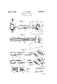
- Fig. 1 is a plan view of an improved battery post extension member illustrated as removably secured or attached at its respective ends to one of the battery terminal posts and to the usual electrical conductor or cable.
- Fig. 2 is a side" View of the same,the extension member being shown in vertical sec- 99 tion to illustrate more clearly the nature of its construction, and the cable connection being omitted.
- Fig. 3 is a view similar to Fig. 1 showing a modified manner of attaching one end of the extension member to the battery post or terminal.
- Fig. 4 is an enlarged vertical section on line H of Fig. 3.
- Fig. 5 is a View similar to Fig. 3 illustrating a further modified form of attachment of the arm to the battery post.
- the battery which is usually of the storage type, is indicated at 1, and 2 represents one of the terminal posts.
- the electrical conductor or cable connection is shown at 8 (Fig. 1) and in the absence of the present improvements the connector 4 of the cable is suitably secured to the post 2.
- the battery post extension member or arm constituting the present invention is indicated generally at5 and comprises a hub portion 6 provided with a vertically disposed preferably tapered aperture 7 adapted for snug engagement with the end of the terminal post 2.
- the extension member further comprises an intermediate elongated portion 8 and an enlarged terminal member or portion 9 which is preferably tapered for snug engagement with the connector 4: of the cable connection.
- the described portions of the extension member 5 are preferably integrally constructed to form a unitary member and thesaid member preferably consists of an alloy metal containing substantially 2% of antimony and 98% St. Joe pure chemical lead.
- the above proportions are illustrative of a preferred embodiment of the invention, but it will be understood that these metals may be combined in other proportions without departing from the nature and scope of the improvements.
- the extension member 5 is or may be further provided with a central embedded wire or strand 10 of copper or other conducting material to facilitate the unobstructed passage of the current through the arm between the battery and the cable conductor 3.
- An outer covering or sleeve 11 of rubber or other insulating material is or may be provided on the elongated portion 8 of the arm for protective purposes and to more effectually guard against accidental short circuits, both in handling the extensionand which might occur from the accidental presence of tools or articles having current conducting properties.
- the hub portion 6 of the arm is burnt or fused at its top to the battery post to provide a semi-permanent engagement to insure against leakage of the current.
- the burnt or fused area of the parts is indicated for example at 12 (Fig. 2) and may be obtained by the usual gasoline or oxy-acetylene Latinas torch.
- the opposite end of the extension arm is securely fastened to the cable 3 by the usual socket or other connection 4: firmly clamped as indicated to the tapered terminal portion 9 of the arm.
- extension arm or member renders the same quite flexible and ductile to permit the arm to be bent or distorted in any desired manner to facilitate its connection or detachment to the cable 3.
- member has been shown as substantially straight and in its preferred construction should have a minimum length of at least six inches.
- the alloy of pure chemical lead and antimony of which the arm is constructed is highly resistant to corrosion and the deposit of sulphates resulting from acid vapors emanating from the battery in the vicinity of the terminal post 2.
- These vapors are particularly manifest when the battery is warm or unduly heated from use and due to the nature of the material constituting the extension member, do not form any deposits or have any corrosive effects at the battery terminal post connection. It will further be apparent that these acid vapors have little or no effect upon the cable connection at the other end of the arm due to the relatively remote situation of this connection from the battery, and also due to the acid-resisting nature of the portion 9 of the arm.
- a modified form of connection is shown for removably securing the hub portion 6 of the arm to the battery post.
- a threaded nut 13 is cast within an enlargement or boss portion 14 of the hub and a bolt or set screw 15 extends through an aperture in the alloy and threadedly engages said nut. 3
- By turning the screw its inner end will be caused to tightly engage the post 2 of the battery for the purpose of rigidly securing the parts together, as will be apparent.
- Fig. 5 a still further modified form of attachment is shown.
- the hub portion 6 of the extension arm is in the form of a split collar for resiliently engaging the post 2 of the battery.
- the integral extended portions 16 of the collar are apertured to receive a bolt or screw 17 having a nut 18 which may be drawn up to rigidly secure the hub portion 6 to the battery post.
- the extension arm 5 being formed of current conducting material serves as a bridge or cushion between the-battery cells and the starting motor and remaining elements of the circuit. It carries and absorbs a certain amount of electricity which serves to prevent undue shock on the battery when the starter button is first depressed, for example in starting heavy automobile motors in cold weather. This cushioning eflect also favorably reacts toward the preservation of the ignition, starting motor and other factors in strength of the battery.
- the alloy of which the arm is constructed is not easily heated and this fact is instrumental in reducing the temperature adjacent the battery thereby retarding the formation of acid vapors, the latter being ordinarily responsive to warm temperatures.
- the extension arm is firmly fixed to the battery terminal and forms a bridge between said terminal and the cable connection. In this manner the arm acts as a physical shock absorber in preventing or retarding any tendency of the battery connection becoming loose in road service which would otherwise result in swaying and vibration of the bat-, tery plates. In this manner the extension further serves to prolong the life and
- the invention further contemplates the extension arm 5 being formed integrally with the battery post or terminal 2, instead of as t. separate member attachable to said-post. For this purpose the battery post terminal 2 would be prolonged for a substantial extent and at its terminalportion would be secured to the cable conductor 3 at a point remote 1 from the battery, in the same manner as the,
- the cable 3 is attached to the end 9 of the arm.
- the arm is formed as described as an integral part of the post 2, it will be understood that corrosion is prevented by reason of the space provided between the connection to the cable terminal and the battery.
- the usual lead construction of the battery post may be employed for this prolongation, or the same may be constructedof an acid resisting metallic alloy, for instance an alloy of lead and antimony as herein described. In either event the prolongation or extension of the battery post terminal would be sufliciently flexible and ductile by reason of the substance of which it is constructed, to permit convenient attachment of the same to the end of the cable or other electrical conductor 3.
- An extension for a storage battery terminal comprising: an elongated deformable member of corrosion resisting alloy consisting of lead and antimony, said member having means at one end thereof for engagement with a terminal of said battery and means at the other end thereof for engagement with an electric conductor of corrodible material;
- An extension arm and cable support for a storage battery terminal comprising an elongated self-supportin member of corrosion resisting alloy, Sai member having 9..
Landscapes
- Connection Of Batteries Or Terminals (AREA)
Description
C. F. BINDER .April 19, 1932.
BATTERY POST EXTENS ION Filed March 12, 1950 I'I' IIIIIIII'II'IA IIIIIIIIIIIIIIIIIIIIIIIIIIIIIIIIIIIIIIIIIIIIIIIL I 1 I I I I u 1 I I 1 I I I I I 1 1 I I I I I I I n I Patented Apr. 19, 1932 PATENT OFFICE CHARLES FREDRICK BINDER, OF ATLANTA, GEORGIA.
BATTERY POST EXTENSION Application filed March 12, 1930. Serial'No. 435,175.
The present invention relates to storage batteries such as automobile, radio and similar batteries, and has for its objects to provide an extension arm or attachment for one or both of the battery terminal posts whereby sulphate deposits and corrosion of the terminals due to acid vapors is eifectually prevented.
The described corrosion of the battery terminal posts usually occurs principally at the positive pole, and is a result of sulphuric or other acid vapors originating within the battery cells. The described acid vapors emanating from the cells have a chemical reaction with the usual current conducting battery connections commonly formed of iron,
brass and copper, with consequent deteriora-- tion of'the life of the battery. Sulphate deposits are formed at the connections which seriously impair the entire electric system, including starting, lighting and generating, when the battery is employed in an automobile.
The above described objectionable corro- 22'5 sion and sulphate deposits are entirely obviated by my invention, and for this. purpose I have provided a unitary extension arm formed of an alloy of acid-resisting material, the use of which will not be attended byany 3Q sulphate deposits resulting from the presence of acid vapors. The extension arm of alloy metal is designed for attachment at one end of the battery post and at its other end to the usual flexible cable conductor 95 which may be grounded or extend to the starting motor. Inthe absence of my invention the free end of the cable is ordinarily secured directly to the battery post. By the invention the connection at the cable terminal is spaced from the battery and a substantial distance from the area of acid fumes which might otherwise have a deteriorating effect on the cable connection.
A further object of the invention isto provide an extension arm of the character described which is of a flexible and ductile nature and may be readily distorted as desired to facilitate its connection between the described battery and cable terminals. In addition to being acid resistant and not sus- 5o ceptible to corrosion, the improved extension arm is constructed to afford unobstructed passage of the electric current through the arm between the respective terminal connections;
The attachment is simple in its nature and may be conveniently secured in place without the use of special tools and may be manufactured economically and to commercial advantage. The invention also acts as a cushion" or shock absorber in service, both with respect to electric current surges and in pre venting undue vibration and swaying of the battery plates, thereby conserving and prolonging the life of the battery.
WVith such objects in view, as well as other advantages which may be incident to the use of the improvements, the invention consists in the parts and combinations thereof hereinafter set forth and claimed, with the understanding that the several necessary elements constituting the same may be varied in proportions and arrangement without departing from the nature and scope of the invention.
In order to make the invention more clear- 1y understood there are shown in the accompanyin'g drawings means for carrying the same into practical eifect, without limiting the improvements, in their useful applications, to the particular constructions which, for the purpose of explanation, have been made the subject of illustration.
In saiddrawings:
Fig. 1 is a plan view of an improved battery post extension member illustrated as removably secured or attached at its respective ends to one of the battery terminal posts and to the usual electrical conductor or cable.
Fig. 2 is a side" View of the same,the extension member being shown in vertical sec- 99 tion to illustrate more clearly the nature of its construction, and the cable connection being omitted.
Fig. 3 is a view similar to Fig. 1 showing a modified manner of attaching one end of the extension member to the battery post or terminal.
Fig. 4 is an enlarged vertical section on line H of Fig. 3.
Fig. 5 is a View similar to Fig. 3 illustrating a further modified form of attachment of the arm to the battery post.
Referring to the drawings:
The battery, which is usually of the storage type, is indicated at 1, and 2 represents one of the terminal posts. The electrical conductor or cable connection is shown at 8 (Fig. 1) and in the absence of the present improvements the connector 4 of the cable is suitably secured to the post 2.
The battery post extension member or arm constituting the present invention is indicated generally at5 and comprises a hub portion 6 provided with a vertically disposed preferably tapered aperture 7 adapted for snug engagement with the end of the terminal post 2. The extension member further comprises an intermediate elongated portion 8 and an enlarged terminal member or portion 9 which is preferably tapered for snug engagement with the connector 4: of the cable connection. The described portions of the extension member 5 are preferably integrally constructed to form a unitary member and thesaid member preferably consists of an alloy metal containing substantially 2% of antimony and 98% St. Joe pure chemical lead. The above proportions are illustrative of a preferred embodiment of the invention, but it will be understood that these metals may be combined in other proportions without departing from the nature and scope of the improvements.
The extension member 5 is or may be further provided with a central embedded wire or strand 10 of copper or other conducting material to facilitate the unobstructed passage of the current through the arm between the battery and the cable conductor 3. An outer covering or sleeve 11 of rubber or other insulating material is or may be provided on the elongated portion 8 of the arm for protective purposes and to more effectually guard against accidental short circuits, both in handling the extensionand which might occur from the accidental presence of tools or articles having current conducting properties.
In the preferred manner of practicing the invention, the hub portion 6 of the arm is burnt or fused at its top to the battery post to provide a semi-permanent engagement to insure against leakage of the current. The burnt or fused area of the parts is indicated for example at 12 (Fig. 2) and may be obtained by the usual gasoline or oxy-acetylene Latinas torch. The opposite end of the extension arm is securely fastened to the cable 3 by the usual socket or other connection 4: firmly clamped as indicated to the tapered terminal portion 9 of the arm.
The nature of the alloy constituting the extension arm or member is such that the latter renders the same quite flexible and ductile to permit the arm to be bent or distorted in any desired manner to facilitate its connection or detachment to the cable 3. For convenience in illustration the member has been shown as substantially straight and in its preferred construction should have a minimum length of at least six inches.
The alloy of pure chemical lead and antimony of which the arm is constructed, is highly resistant to corrosion and the deposit of sulphates resulting from acid vapors emanating from the battery in the vicinity of the terminal post 2. These vapors are particularly manifest when the battery is warm or unduly heated from use and due to the nature of the material constituting the extension member, do not form any deposits or have any corrosive effects at the battery terminal post connection. It will further be apparent that these acid vapors have little or no effect upon the cable connection at the other end of the arm due to the relatively remote situation of this connection from the battery, and also due to the acid-resisting nature of the portion 9 of the arm.
In Fig. 3 a modified form of connection is shown for removably securing the hub portion 6 of the arm to the battery post. A threaded nut 13 is cast within an enlargement or boss portion 14 of the hub and a bolt or set screw 15 extends through an aperture in the alloy and threadedly engages said nut. 3 By turning the screw its inner end will be caused to tightly engage the post 2 of the battery for the purpose of rigidly securing the parts together, as will be apparent.
In Fig. 5 a still further modified form of attachment is shown. The hub portion 6 of the extension arm is in the form of a split collar for resiliently engaging the post 2 of the battery. The integral extended portions 16 of the collar are apertured to receive a bolt or screw 17 having a nut 18 which may be drawn up to rigidly secure the hub portion 6 to the battery post.
The extension arm 5 being formed of current conducting material serves as a bridge or cushion between the-battery cells and the starting motor and remaining elements of the circuit. It carries and absorbs a certain amount of electricity which serves to prevent undue shock on the battery when the starter button is first depressed, for example in starting heavy automobile motors in cold weather. This cushioning eflect also favorably reacts toward the preservation of the ignition, starting motor and other factors in strength of the battery.
the circuit. The alloy of which the arm is constructed is not easily heated and this fact is instrumental in reducing the temperature adjacent the battery thereby retarding the formation of acid vapors, the latter being ordinarily responsive to warm temperatures. The extension arm is firmly fixed to the battery terminal and forms a bridge between said terminal and the cable connection. In this manner the arm acts as a physical shock absorber in preventing or retarding any tendency of the battery connection becoming loose in road service which would otherwise result in swaying and vibration of the bat-, tery plates. In this manner the extension further serves to prolong the life and The invention further contemplates the extension arm 5 being formed integrally with the battery post or terminal 2, instead of as t. separate member attachable to said-post. For this purpose the battery post terminal 2 would be prolonged for a substantial extent and at its terminalportion would be secured to the cable conductor 3 at a point remote 1 from the battery, in the same manner as the,
What is claimed is a 1. An extension for a storage battery terminal comprising: an elongated deformable member of corrosion resisting alloy consisting of lead and antimony, said member having means at one end thereof for engagement with a terminal of said battery and means at the other end thereof for engagement with an electric conductor of corrodible material;
and a core of relatively high current conducting material extending longitudinally.
collar at one end thereof for engagement with a terminal of said battery and having means at its other end for connection with a battery cable connector, and said member. being also deformable transversely of its length to effect a connection with said cable connector at selected points spaced a substantial distance from said battery, and from the acid fumes emanating therefrom.
In testimony whereof I aifix my signature.
CHARLES FREDRICK BINDER.
acid fumes emanating from said battery, and
the deformability of said member adapting it for attachment to said conductorat various locations relative to said terminal.
2. An extension arm and cable support for a storage battery terminal, comprising an elongated self-supportin member of corrosion resisting alloy, Sai member having 9..
Priority Applications (1)
| Application Number | Priority Date | Filing Date | Title |
|---|---|---|---|
| US435175A US1854328A (en) | 1930-03-12 | 1930-03-12 | Battery post extension |
Applications Claiming Priority (1)
| Application Number | Priority Date | Filing Date | Title |
|---|---|---|---|
| US435175A US1854328A (en) | 1930-03-12 | 1930-03-12 | Battery post extension |
Publications (1)
| Publication Number | Publication Date |
|---|---|
| US1854328A true US1854328A (en) | 1932-04-19 |
Family
ID=23727317
Family Applications (1)
| Application Number | Title | Priority Date | Filing Date |
|---|---|---|---|
| US435175A Expired - Lifetime US1854328A (en) | 1930-03-12 | 1930-03-12 | Battery post extension |
Country Status (1)
| Country | Link |
|---|---|
| US (1) | US1854328A (en) |
Cited By (6)
| Publication number | Priority date | Publication date | Assignee | Title |
|---|---|---|---|---|
| US2684991A (en) * | 1950-10-31 | 1954-07-27 | Charles A Marks | Terminal connection for lead storage batteries and method and apparatus for forming the same |
| US2937357A (en) * | 1955-01-20 | 1960-05-17 | William R Kennedy | Electrical connector for printed circuits |
| US3037150A (en) * | 1959-01-08 | 1962-05-29 | Eagle Picher Co | Grounded floating mounting ring |
| USD276424S (en) | 1982-05-26 | 1984-11-20 | Pietro Di Piazza | Battery terminal connector |
| US4695118A (en) * | 1985-07-02 | 1987-09-22 | Garnik Magdesyan | Battery terminal post clamp |
| US4760000A (en) * | 1986-04-01 | 1988-07-26 | Williams Fred G | Battery terminal assembly |
-
1930
- 1930-03-12 US US435175A patent/US1854328A/en not_active Expired - Lifetime
Cited By (6)
| Publication number | Priority date | Publication date | Assignee | Title |
|---|---|---|---|---|
| US2684991A (en) * | 1950-10-31 | 1954-07-27 | Charles A Marks | Terminal connection for lead storage batteries and method and apparatus for forming the same |
| US2937357A (en) * | 1955-01-20 | 1960-05-17 | William R Kennedy | Electrical connector for printed circuits |
| US3037150A (en) * | 1959-01-08 | 1962-05-29 | Eagle Picher Co | Grounded floating mounting ring |
| USD276424S (en) | 1982-05-26 | 1984-11-20 | Pietro Di Piazza | Battery terminal connector |
| US4695118A (en) * | 1985-07-02 | 1987-09-22 | Garnik Magdesyan | Battery terminal post clamp |
| US4760000A (en) * | 1986-04-01 | 1988-07-26 | Williams Fred G | Battery terminal assembly |
Similar Documents
| Publication | Publication Date | Title |
|---|---|---|
| US4848616A (en) | Electric immersion heating unit with readily removable and replaceable galvanic current control resistor | |
| US4058701A (en) | Glow element arrangement for electric cigarette lighters | |
| US1854328A (en) | Battery post extension | |
| US3128139A (en) | Spark plug shield | |
| US5403678A (en) | Corrosion-resistant and protective terminal structure for a battery post | |
| US4174873A (en) | Electrical connector for a vehicle | |
| US2297916A (en) | Marine flagpole light and socket | |
| US2353199A (en) | Resistor for spark plugs | |
| US2139742A (en) | Service entrance device | |
| US1991574A (en) | Radio interference suppressor | |
| US1910788A (en) | Battery post terminal extension | |
| US2038353A (en) | Generator terminal shield | |
| US1926163A (en) | Cable terminal | |
| US894705A (en) | Protective device. | |
| US1353593A (en) | Spark-plug | |
| US2286415A (en) | Battery connector | |
| US1987575A (en) | By-pass for high tension electricity | |
| US1975355A (en) | Mounting means | |
| US2077522A (en) | Battery connecter | |
| US2277358A (en) | Marine flagpole light and socket | |
| US2685012A (en) | Protective switch for motor vehicle storage batteries | |
| US2045361A (en) | Protective sleeve for resistor connecter device | |
| US1554271A (en) | Spark-plug structure | |
| US1435317A (en) | Renewable fuse | |
| US2899478A (en) | Spark modifier for spark plugs and ignition systems |