US1854317A - Pump - Google Patents
Pump Download PDFInfo
- Publication number
- US1854317A US1854317A US457229A US45722930A US1854317A US 1854317 A US1854317 A US 1854317A US 457229 A US457229 A US 457229A US 45722930 A US45722930 A US 45722930A US 1854317 A US1854317 A US 1854317A
- Authority
- US
- United States
- Prior art keywords
- pump
- liquid
- container
- conduit
- minimum level
- Prior art date
- Legal status (The legal status is an assumption and is not a legal conclusion. Google has not performed a legal analysis and makes no representation as to the accuracy of the status listed.)
- Expired - Lifetime
Links
- 239000007788 liquid Substances 0.000 description 21
- 239000003921 oil Substances 0.000 description 3
- QSHDDOUJBYECFT-UHFFFAOYSA-N mercury Chemical compound [Hg] QSHDDOUJBYECFT-UHFFFAOYSA-N 0.000 description 2
- 229910052753 mercury Inorganic materials 0.000 description 2
- 238000010276 construction Methods 0.000 description 1
- 239000000295 fuel oil Substances 0.000 description 1
- 238000012423 maintenance Methods 0.000 description 1
- 230000008520 organization Effects 0.000 description 1
Images
Classifications
-
- F—MECHANICAL ENGINEERING; LIGHTING; HEATING; WEAPONS; BLASTING
- F04—POSITIVE - DISPLACEMENT MACHINES FOR LIQUIDS; PUMPS FOR LIQUIDS OR ELASTIC FLUIDS
- F04D—NON-POSITIVE-DISPLACEMENT PUMPS
- F04D29/00—Details, component parts, or accessories
- F04D29/60—Mounting; Assembling; Disassembling
- F04D29/605—Mounting; Assembling; Disassembling specially adapted for liquid pumps
- F04D29/606—Mounting in cavities
-
- Y—GENERAL TAGGING OF NEW TECHNOLOGICAL DEVELOPMENTS; GENERAL TAGGING OF CROSS-SECTIONAL TECHNOLOGIES SPANNING OVER SEVERAL SECTIONS OF THE IPC; TECHNICAL SUBJECTS COVERED BY FORMER USPC CROSS-REFERENCE ART COLLECTIONS [XRACs] AND DIGESTS
- Y10—TECHNICAL SUBJECTS COVERED BY FORMER USPC
- Y10T—TECHNICAL SUBJECTS COVERED BY FORMER US CLASSIFICATION
- Y10T137/00—Fluid handling
- Y10T137/2496—Self-proportioning or correlating systems
- Y10T137/2559—Self-controlled branched flow systems
- Y10T137/2564—Plural inflows
- Y10T137/2567—Alternate or successive inflows
- Y10T137/2569—Control by depletion of source
-
- Y—GENERAL TAGGING OF NEW TECHNOLOGICAL DEVELOPMENTS; GENERAL TAGGING OF CROSS-SECTIONAL TECHNOLOGIES SPANNING OVER SEVERAL SECTIONS OF THE IPC; TECHNICAL SUBJECTS COVERED BY FORMER USPC CROSS-REFERENCE ART COLLECTIONS [XRACs] AND DIGESTS
- Y10—TECHNICAL SUBJECTS COVERED BY FORMER USPC
- Y10T—TECHNICAL SUBJECTS COVERED BY FORMER US CLASSIFICATION
- Y10T137/00—Fluid handling
- Y10T137/2496—Self-proportioning or correlating systems
- Y10T137/2559—Self-controlled branched flow systems
- Y10T137/2574—Bypass or relief controlled by main line fluid condition
- Y10T137/2577—Liquid level responsive
-
- Y—GENERAL TAGGING OF NEW TECHNOLOGICAL DEVELOPMENTS; GENERAL TAGGING OF CROSS-SECTIONAL TECHNOLOGIES SPANNING OVER SEVERAL SECTIONS OF THE IPC; TECHNICAL SUBJECTS COVERED BY FORMER USPC CROSS-REFERENCE ART COLLECTIONS [XRACs] AND DIGESTS
- Y10—TECHNICAL SUBJECTS COVERED BY FORMER USPC
- Y10T—TECHNICAL SUBJECTS COVERED BY FORMER US CLASSIFICATION
- Y10T137/00—Fluid handling
- Y10T137/8593—Systems
- Y10T137/86493—Multi-way valve unit
- Y10T137/86863—Rotary valve unit
- Y10T137/86871—Plug
Definitions
- the present invention relates to pumps, and more particularly to booster pumps.
- a pump of the character above ins dicated having a float-operated valve for closing the intake conduit and opening a second conduit when the liquid within the container falls below the normal minimum level, to provide such a valve for closing the intake conduit and opening a minimum liquid level, conduit when the liquid within the container falls below the normal minimum level; and, generally, to provide improved means of that character such as hereinafter apear.
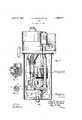
- Figure 1 is a front elevational view of .the entire pump unit, certain portions being broken away to better illustrate the inside operating parts;
- Figure 2 is a vertical sectional view of the float-operated valve housing with the valve being indicated in its two operative positions;
- Figure 3 is a sectional view of the valvel per se.
- the booster pump comprises a container 1 adapted to hold a liquid 2 such as fuel oil.
- the container has a cover plate 3 secured to its upper end by suitable means such as screws 4.
- y- Mounted on the upper side of this cover plate is an electric motor 5 within an electric circuit 6 whose shaft is connected to the shaft 7 of a rotary pump 8 which supplies liquid to the container through an intake conduit 9 which has an intake port 10 connected to a suitable source of liquid supply not shown.
- This conduit is connected to the pump 8 by means of the short curved pipe 11 and the T-union 12 which houses a lioatoperated and controlled rotatable valve 13 1930.
- a minimum liquid level conduit 14 is likewise connected to the T-union 12 and its intake port 15 extends below the vertically projectingoutlet port 16 of the container to insure the obvious maintenance of a minimum level 77 therein.
- a switch 17 of the mercury type and within the motor circuit 6 is operated by the float 18'which is limitedly slidably carried on the vertically disposed stem 19 between the stops 20, 21 thereon.
- the stem 19 is pivotally secured at its upper end to the farm 22 connected to the switch 17 and the stem lslidably passes through an aperture 23 of the laterally projecting rod 24 intermediate its ends for maintaining the stem in a substantially vertical position.
- the normal minimum level 25 which is normally maintained by the float-operated switch 17
- a minimum level 77 is maintained within the container by the upwardlyextending outlet port. 16.
- the float 26 falls to the position shown in dotted lines.
- valve 13 which is originally in the position shown in Figure 2, rotates to the position shown in dotted lines and the pump thus continues to pump liquidV through the minimum level conduit 14 and exhaust it through the outlet port 28 of the pump inoff the motor 5 and its driven pump 8.
- the float 18 falls and abuts the stop 21 which closes the tiltable mercury switch 17 to turn on the motor 5 to drive the pump 8.
- the float operated and controlled valve 13, within the lT-union housing 12 is provided with two angular bores 29, 30 connected at right angles with each other.
- this valve When this valve is in the position shown in full lines in Figure 2, the pump draws the liquid from the intake conduit 9 and when in the position shown in dotted lines, it draws the liquid through the minimum level conduit 14.
- the manually operable lever 31 secured to the arm 32 intermediate the ioat 26 and the valve 13 is provided to lift the float when the source of liquid supply is replenished, thus permitting the unit to again renew its normal operation when the normal minimum level 25 is regained within the container.
- a container adapted to hold a liquid, a liquid intake conduit, an electrically operated pump within an electric circuit for drawing liquid into said container through said conduit, an electric switch within said circuit, a float within said container operatively associated with said switch for opening said switch by the movement of the ioat in one direction and for closing the switch by the movement of the float in the opposite direction for maintaining the liquid therein between normal maximum and normal minimum levels, a second conduit connected to said pump for supplying liquid within the container to said llO
Landscapes
- Engineering & Computer Science (AREA)
- Mechanical Engineering (AREA)
- General Engineering & Computer Science (AREA)
- Jet Pumps And Other Pumps (AREA)
Description
April 19, 1932 J. E'. TEESDALE ET AL PUMP Filed May 29, 1930 lll 75h22 eefda Ze gg) ydefz'.. fee/'dale' i if/Ra.
Patented Apr. 19, 1932 UNTED STFTSS JOHN B. TEESDALE AND CLYD-E H. 'IEESDALE OF GRAND RAPIDS, MICHIGAN, AS- -A SIGNORS TO TEESDALE MANUFACTURING- COMPANY, F GRAND RAPIDS, MICHIGAN,
A CORPORATION OF MICHIGAN PUMP Application filed May 29,
The present invention relates to pumps, and more particularly to booster pumps.
he main objects of the invention areto provide a pump of the character above ins dicated having a float-operated valve for closing the intake conduit and opening a second conduit when the liquid within the container falls below the normal minimum level, to provide such a valve for closing the intake conduit and opening a minimum liquid level, conduit when the liquid within the container falls below the normal minimum level; and, generally, to provide improved means of that character such as hereinafter apear.
An illustrative embodiment of the invention is shown in the accompanying drawings, wherein:
Figure 1 is a front elevational view of .the entire pump unit, certain portions being broken away to better illustrate the inside operating parts;
Figure 2 is a vertical sectional view of the float-operated valve housing with the valve being indicated in its two operative positions; and
Figure 3 is a sectional view of the valvel per se.
Referring to the drawings, the booster pump comprises a container 1 adapted to hold a liquid 2 such as fuel oil. The container has a cover plate 3 secured to its upper end by suitable means such as screws 4. y- Mounted on the upper side of this cover plate is an electric motor 5 within an electric circuit 6 whose shaft is connected to the shaft 7 of a rotary pump 8 which supplies liquid to the container through an intake conduit 9 which has an intake port 10 connected to a suitable source of liquid supply not shown. This conduit is connected to the pump 8 by means of the short curved pipe 11 and the T-union 12 which houses a lioatoperated and controlled rotatable valve 13 1930. Serial No. 457,229.
whose function and purpose will hereinafter appear.
A minimum liquid level conduit 14 is likewise connected to the T-union 12 and its intake port 15 extends below the vertically projectingoutlet port 16 of the container to insure the obvious maintenance of a minimum level 77 therein.
A switch 17 of the mercury type and within the motor circuit 6 is operated by the float 18'which is limitedly slidably carried on the vertically disposed stem 19 between the stops 20, 21 thereon. The stem 19 is pivotally secured at its upper end to the farm 22 connected to the switch 17 and the stem lslidably passes through an aperture 23 of the laterally projecting rod 24 intermediate its ends for maintaining the stem in a substantially vertical position. When the normal minimum level 25 (which is normally maintained by the float-operated switch 17) falls below such level, a minimum level 77 is maintained within the container by the upwardlyextending outlet port. 16. As the liquid within the container thus Jfalls below the normal minimum level 25 to the minimum level 77 the float 26 falls to the position shown in dotted lines. `During this movement, the valve 13 which is originally in the position shown in Figure 2, rotates to the position shown in dotted lines and the pump thus continues to pump liquidV through the minimum level conduit 14 and exhaust it through the outlet port 28 of the pump inoff the motor 5 and its driven pump 8. As the liquid is withdrawn from the container 1, the float 18 falls and abuts the stop 21 which closes the tiltable mercury switch 17 to turn on the motor 5 to drive the pump 8.
In the event, however, that the source of liquid supply to the container fails or is exhausted, the liquid within the container will fall from the normal minimum level 25 to the minimum level 77.
The float operated and controlled valve 13, within the lT-union housing 12 is provided with two angular bores 29, 30 connected at right angles with each other. When this valve is in the position shown in full lines in Figure 2, the pump draws the liquid from the intake conduit 9 and when in the position shown in dotted lines, it draws the liquid through the minimum level conduit 14.
lVlien therefore the source of liquid supply thus becomes exhausted, and the liquid falls to the minimum level 77, the pump will nevertheless continue to pump oil through the minimum level conduit 14 rather than air. The manually operable lever 31 secured to the arm 32 intermediate the ioat 26 and the valve 13 is provided to lift the float when the source of liquid supply is replenished, thus permitting the unit to again renew its normal operation when the normal minimum level 25 is regained within the container.
It will be understood of course that the upwardly extending outlet port 16 may be dispensed with in which event however, the pump will draw air through the conduit 14: instead of oil when the oil has become eX- hausted in the container.
It will thus be seen that a novel device is herein shown and described which provides alternate means for accomplishing the objects generally attained in the Teesdale patent hereinabove mentioned.
While but one specific embodiment of this invention has been herein shown and described, it will be understood that numerous details of the construction shown may be altered or omitted without departing from the spirit of this invention as defined by the following claim.
I claim:
In an organization of the class described, a container adapted to hold a liquid, a liquid intake conduit, an electrically operated pump within an electric circuit for drawing liquid into said container through said conduit, an electric switch within said circuit, a float within said container operatively associated with said switch for opening said switch by the movement of the ioat in one direction and for closing the switch by the movement of the float in the opposite direction for maintaining the liquid therein between normal maximum and normal minimum levels, a second conduit connected to said pump for supplying liquid within the container to said llO
Priority Applications (1)
| Application Number | Priority Date | Filing Date | Title |
|---|---|---|---|
| US457229A US1854317A (en) | 1930-05-29 | 1930-05-29 | Pump |
Applications Claiming Priority (1)
| Application Number | Priority Date | Filing Date | Title |
|---|---|---|---|
| US457229A US1854317A (en) | 1930-05-29 | 1930-05-29 | Pump |
Publications (1)
| Publication Number | Publication Date |
|---|---|
| US1854317A true US1854317A (en) | 1932-04-19 |
Family
ID=23815921
Family Applications (1)
| Application Number | Title | Priority Date | Filing Date |
|---|---|---|---|
| US457229A Expired - Lifetime US1854317A (en) | 1930-05-29 | 1930-05-29 | Pump |
Country Status (1)
| Country | Link |
|---|---|
| US (1) | US1854317A (en) |
Cited By (3)
| Publication number | Priority date | Publication date | Assignee | Title |
|---|---|---|---|---|
| US2548241A (en) * | 1948-09-02 | 1951-04-10 | Lyon Ind Inc | Beverage dispensing apparatus |
| US4683864A (en) * | 1985-04-11 | 1987-08-04 | Whitehead Engineered Products, Inc. | Fuel routing systems for fuel-injected engines |
| US5642719A (en) * | 1995-09-11 | 1997-07-01 | Ford Motor Company | Automotive fuel delivery module with fuel level actuated reservoir |
-
1930
- 1930-05-29 US US457229A patent/US1854317A/en not_active Expired - Lifetime
Cited By (3)
| Publication number | Priority date | Publication date | Assignee | Title |
|---|---|---|---|---|
| US2548241A (en) * | 1948-09-02 | 1951-04-10 | Lyon Ind Inc | Beverage dispensing apparatus |
| US4683864A (en) * | 1985-04-11 | 1987-08-04 | Whitehead Engineered Products, Inc. | Fuel routing systems for fuel-injected engines |
| US5642719A (en) * | 1995-09-11 | 1997-07-01 | Ford Motor Company | Automotive fuel delivery module with fuel level actuated reservoir |
Similar Documents
| Publication | Publication Date | Title |
|---|---|---|
| US1760382A (en) | Controlling means for electric switches | |
| US1854317A (en) | Pump | |
| US2250271A (en) | Sump pump priming device | |
| US1577622A (en) | Liquid-fuel burner | |
| US2496467A (en) | Pump shutoff mechanism | |
| US1875398A (en) | Ptjmp | |
| US1304195A (en) | Automatic gas-burner | |
| US2798436A (en) | Oil pumping apparatus | |
| US1594483A (en) | Sewage-ejector system | |
| US2341145A (en) | Liquid feeding means | |
| US2652688A (en) | Vertical axis, pump and turbine hydraulic coupling | |
| US2927597A (en) | Priming device for pumps | |
| US1389907A (en) | Water-inlet valve for tanks | |
| US1473441A (en) | Automatic motor switch | |
| US1838443A (en) | Pump | |
| US1295446A (en) | Pneumatic water-elevator. | |
| US1520248A (en) | Refrigerator unit for domestic refrigerators | |
| US1869030A (en) | Float-operated electric switch | |
| US1269697A (en) | Automatic vacuum-maintaining apparatus. | |
| US2689628A (en) | Automatic oil level control device | |
| US2126847A (en) | Liquid dispensing means | |
| US3292548A (en) | Suction pump unit for oil supply installations | |
| US1377277A (en) | Vacuum feed apparatus | |
| US2165585A (en) | Automatic feeding device for liquid fuel and the like | |
| US1731684A (en) | Dispensing pump |