US1854217A - Envelope machine - Google Patents
Envelope machine Download PDFInfo
- Publication number
- US1854217A US1854217A US319502A US31950228A US1854217A US 1854217 A US1854217 A US 1854217A US 319502 A US319502 A US 319502A US 31950228 A US31950228 A US 31950228A US 1854217 A US1854217 A US 1854217A
- Authority
- US
- United States
- Prior art keywords
- blanks
- magazine
- patch
- blank
- envelope
- Prior art date
- Legal status (The legal status is an assumption and is not a legal conclusion. Google has not performed a legal analysis and makes no representation as to the accuracy of the status listed.)
- Expired - Lifetime
Links
- 230000007246 mechanism Effects 0.000 description 30
- 230000002093 peripheral effect Effects 0.000 description 4
- 241000517645 Abra Species 0.000 description 2
- 230000004075 alteration Effects 0.000 description 1
- 230000015572 biosynthetic process Effects 0.000 description 1
- 238000010276 construction Methods 0.000 description 1
- 238000000151 deposition Methods 0.000 description 1
- 238000001035 drying Methods 0.000 description 1
- 230000004048 modification Effects 0.000 description 1
- 238000012986 modification Methods 0.000 description 1
- 238000007789 sealing Methods 0.000 description 1
- 238000000926 separation method Methods 0.000 description 1
Images
Classifications
-
- B—PERFORMING OPERATIONS; TRANSPORTING
- B31—MAKING ARTICLES OF PAPER, CARDBOARD OR MATERIAL WORKED IN A MANNER ANALOGOUS TO PAPER; WORKING PAPER, CARDBOARD OR MATERIAL WORKED IN A MANNER ANALOGOUS TO PAPER
- B31B—MAKING CONTAINERS OF PAPER, CARDBOARD OR MATERIAL WORKED IN A MANNER ANALOGOUS TO PAPER
- B31B70/00—Making flexible containers, e.g. envelopes or bags
- B31B70/74—Auxiliary operations
- B31B70/81—Forming or attaching accessories, e.g. opening devices, closures or tear strings
- B31B70/82—Forming or attaching windows
- B31B70/826—Forming or attaching windows involving applying window patches
-
- B—PERFORMING OPERATIONS; TRANSPORTING
- B31—MAKING ARTICLES OF PAPER, CARDBOARD OR MATERIAL WORKED IN A MANNER ANALOGOUS TO PAPER; WORKING PAPER, CARDBOARD OR MATERIAL WORKED IN A MANNER ANALOGOUS TO PAPER
- B31B—MAKING CONTAINERS OF PAPER, CARDBOARD OR MATERIAL WORKED IN A MANNER ANALOGOUS TO PAPER
- B31B2150/00—Flexible containers made from sheets or blanks, e.g. from flattened tubes
-
- B—PERFORMING OPERATIONS; TRANSPORTING
- B31—MAKING ARTICLES OF PAPER, CARDBOARD OR MATERIAL WORKED IN A MANNER ANALOGOUS TO PAPER; WORKING PAPER, CARDBOARD OR MATERIAL WORKED IN A MANNER ANALOGOUS TO PAPER
- B31B—MAKING CONTAINERS OF PAPER, CARDBOARD OR MATERIAL WORKED IN A MANNER ANALOGOUS TO PAPER
- B31B2160/00—Shape of flexible containers
- B31B2160/10—Shape of flexible containers rectangular and flat, i.e. without structural provision for thickness of contents
-
- B—PERFORMING OPERATIONS; TRANSPORTING
- B31—MAKING ARTICLES OF PAPER, CARDBOARD OR MATERIAL WORKED IN A MANNER ANALOGOUS TO PAPER; WORKING PAPER, CARDBOARD OR MATERIAL WORKED IN A MANNER ANALOGOUS TO PAPER
- B31B—MAKING CONTAINERS OF PAPER, CARDBOARD OR MATERIAL WORKED IN A MANNER ANALOGOUS TO PAPER
- B31B70/00—Making flexible containers, e.g. envelopes or bags
- B31B70/74—Auxiliary operations
- B31B70/81—Forming or attaching accessories, e.g. opening devices, closures or tear strings
- B31B70/82—Forming or attaching windows
-
- Y—GENERAL TAGGING OF NEW TECHNOLOGICAL DEVELOPMENTS; GENERAL TAGGING OF CROSS-SECTIONAL TECHNOLOGIES SPANNING OVER SEVERAL SECTIONS OF THE IPC; TECHNICAL SUBJECTS COVERED BY FORMER USPC CROSS-REFERENCE ART COLLECTIONS [XRACs] AND DIGESTS
- Y10—TECHNICAL SUBJECTS COVERED BY FORMER USPC
- Y10S—TECHNICAL SUBJECTS COVERED BY FORMER USPC CROSS-REFERENCE ART COLLECTIONS [XRACs] AND DIGESTS
- Y10S493/00—Manufacturing container or tube from paper; or other manufacturing from a sheet or web
- Y10S493/916—Pliable container
- Y10S493/917—Envelope
- Y10S493/919—Envelope having window
Definitions
- Figure 1 is a sectional, side elevation showing an embodiment of the invention combined with a standard machine of the type referred to;
- Figure 2 is a plan view of the mechanism illustrated in Figure 1;
- Figure 3 is a plan view of an envelope blank of the type operated upon by the mec anism illustrated, and showin the'blank 1n the condition in which it is de ivered by the novel mechanism to the standard part of the machine.
- the envelope blank comprises a central body portion 1 having a window opening 2 provided therein and having top and bottom flaps 3 and 4 and side flaps 5 pro ecting therefrom.
- the novel mechanism of the present blank in the condition described above to apply to the blank a transparent win ow patch 6, and to deliver such blank to the mechanism for. umming the blank and folding it into a finished envelope.
- invention is designed to receive a are withdrawn singly from the bottom of the hopper and are carried by conveying means, past gumming mechanism 8 which applies gum around the window opening, thence past a patch applying mechanism 9, and finally to a second magazine 10 which forms the introductory magazine illustrated in my application referred to above. withdrawn singly from the bottom of this second magazine and are fed through the subsequent instrumentalities of the machine in the usual way for the performance of the subsequent operations upon the blanks.
- the magazine 7 comprises upright rods 11 arranged to maintain the blanks in registering stacked form, and supporting means for the stack consisting of oppositely rotating discs 12 and 13.
- the discs 12 and 13 are The blanks are slotted to form separating fingers 14 and 15 which are arranged to pass between the lowermost blank and the remainder of the stack to segregate such blank from the stack.
- the bottom flaps of the blanks are turned toward the front of the machine in a position to be operated upon byblank separating mechanism which prepares the lowermost blank for complete separation from the stack by the discs 12 and 13.
- the forward extremities of the bottom flaps are supported somewhat above the plane of the separator discs by a finger 16 and. the blanks are withdrawn past this finger one by one and swun downward by a reciprocating pneumatic pic er 1.7.
- the separating fingers 14 and 15 advance to blank engaging position and perform their separating function.
- Presser fingers 18 advance to press the separated blank beneath rollers 19 and against the-traveling belt 20 against which the rollers 19 that described in my pending application,
- the separator fingers 14 and 15 are cut away at their extremities and made blunt, the inner ends of their leading edges being located to escape engagement wlth the window openings of the envelopes. This obviates all danger of snagging and tearing the envelopes by said fingers.
- the conveying belt 20 runs upon a roller 21 and a drum 22. As the blanks pass downwardly around the drum 22 they come under the influence of a second conveyor consisting of a belt 23 which runs upon rollers 24, 25 and 26. This belt serves to grip the blanks to the belt 20 and in cooperation with the drum 22 and the belt 20 inverts the blanks.
- the belt 23 has its active stretch supported in part by tables 27 and 28, and serves, in conjunction with feed rolls 29 and 30, to conduct the inverted blanks past the gummer 8.
- the gummer comprises a um box 31, the lower end of which is closed y a gum transferring roller 32.
- a roller 33 rotates beneath the roller 32 and carries a raised gum applying segment or die 34, which receives gum from the roller 32 and applies it to the margin of the window opening of an envelope blank at a short distance outward from the edge of such opening.
- the gummed area is indicated at 35 in Figure 3 and the gum applying die has a gum applying surface of the same shape as the gummed area.
- the conveyor belt 23 feeds the gummed blanks onto a short table 36 which extends between a feed roller 37 and a patch applying member 38, and which lies in a groove of the roller 37 with its upper surface substantially tangent to the periphery of such roller.
- a short table 36 which extends between a feed roller 37 and a patch applying member 38, and which lies in a groove of the roller 37 with its upper surface substantially tangent to the periphery of such roller.
- Each blank, while supported on this table, has a window patch applied to it.
- a web of window patch material 39 is supplied from a reel 40, being drawn from the reel by feed rollers 41 driven at a peripheral speed such that a patch length of the web is fed for each envelope blank separated from the magazine 7.
- the web is advanced by rollers 41 between the patch applying member 38 and a severing member 42.
- the patch applying member 38 makes one complete revolution for each envelope blank separated from the magazine 7 and is equal in circumferential extent to the extent of movement of the conveyor belt 23 occurring in one complete cycle of the blank separating mechanism.
- the member 38 is provided with radial passages 43 which extend from the periphery of the member 38 and communicate through an axial passage 44 with a source of suction. Immediately following the open ends of the passages 43 in the member 38 provision is made of a cutting blade 45.
- the mechanism is so timed that as the suction passages 43 come beneath the end of the patch web in position to act upon it, the cutting member 42 in cooperation with the blade 45, severs a charged in the identical patch from the end of the web.
- the patch is then held to the member 38 by the suction means and is carried around and applied to the gummed envelope blank.
- the envelope blank passes between conveyor belts 46 and 47.
- the former belt runs upon rollers 48, 49 and 50 and partially embraces a drum 51.
- the belt 47 runs upon a roller 52 and the drum 51.
- These conveyor belts cooperate to carry the blanks around the drum-51 and thereby to re-invert the blanks so that the patch side is turned downward and the blanks are disposition which they occupied in the magazine 7.
- the blanks pass from between the belts 46 and 47 across an inclined shelf or table 53 and are delivered one by one into the receiving magazine 10.
- the magazine 10 and the separating mechanism for taking the blanks therefrom are, element for element, duplicates of the magazine 7 and the separating mechanism for taking the blanks from the magazine 7.
- the corresponding elements have accordingly been numbered with corresponding numerals followed by the letter a, and will not be described in detail.
- the two separating mechanisms operate in unison, so that for each blank delivered to the magazine 10 at the top thereof, a blank is withdrawn from the bottom of the magazine.
- the conveying mechanism for conducting the blanks away from the magazine 7, however, is operated at such a speed that the blanks are completely separated and spaced from one another so that the may be individually treated in passing beneath the gumming mechanism 8 and the patch applying mechanism 9, whereas the conveying mechanism for conducting the blanks away from the magazine 10 operates at relatively low speed to carry the blanks away in fanned out relation.
- the mechanism of the standard machine described in my application referred to Such mechanism comprises a conveyor belt 54 which runs upon a roller 55 and a drum 56.
- a belt conveyor 56a cooperates with the belt 54 and the drum 56. The blanks are conducted around the drum 56 and onto a drum.
- an envelope machine in combination, means for taking window envelope blanks singly from a stack, mechanism for applying window patches to the upper faces of the blanks, a receivingmagazine, means for conveying the blanks from the patch applying mechanism to the receiving magazine, arranged to invert the blanks to turn them patch side down while they are being conveyed, and means for withdrawing the blanks from said receiving magazine and umming marginal portions of those faces 0 said blanks which are turned downward in said receiving magazine.
- an envelope machine in combination, means for taking window envelope blanks singly from a stack, mechanism for applying window patches to the u per faces of the blanks, a receiving magazine, means for conveying the blanks from the patch applying mechanism and de ositing them patch side down in the top of the receivin magazine, and means for separating and feeding the blanks singly from the bottom of the receiving magazine, and gumming marginal portions of those faces of said blankswhich are turned downward in said receiving magazine.
- a magazine se arating means for removing blanks singly rom the bottom of the magazine and inverting them, means for applying patches to the faces of .the blanks turned upward bv such inversion
- a second magazine means for reinverting the blanks and deposit ing them in'stacked formation in the second magazine
- separating means for removing blanks singly from the bottom of the second magazine, the second magazine and separating means being of the same construction as the first magazine and separating means referred to, and means for applying gum to the faces of the blanks which were turned downward in the second magazine.
- conveying means for conducting the withdrawn blanks away from the magazine so rapidly that the blanks are conveyed in spaced relation, means for appl 'ng window patches to the faces of the blan which are turnedupward while they are being so conveyed, the conveying means being arranged to invert the blanks after application of the a second separating means operating in unison with the first, conveying means operating at relatively low speed to conduct the blanks away from the second magazine in fanned out relation, and means for applying gum to the faces of the blanks which were turned downward in the second magazine.
- means for feeding envelope blanks past a window patch applying station in spaced, definitely timed relation means for feeding a window patch web at a rate such that a patch of the desired length may be supplied for each blank, means for severing patches from the web and applying them to the envelope blanks comprising a pair of cutting elements, one of said elements constituting also a rotary patch carrier and being provided with means for holding a patch by suction, and the other being adapted to follow the severed patch for a short distance to assist in accelerating it to the peripheral speed of the patch carrier. 6.
- an envelope machine in combination, means for feeding envelope blanks in definitely timed, spaced relation, a patch carrying and applying member running in engagement with the blanks'and synchronously with the timing thereof, means for feeding a patch web a distance of one patch length for each envelope blank, and means cooperating with the patch carrier in severing patches from the web, and patches to the peripheral speed of the patch carr1er.
- a window patch applying mechanism for an envelope machine in combination means for feedmg a patch web, a cutting and carrying member rotating adjacent the path of the web, said member includedin suction means and a severing blade closely ollowing the suction means, and means cooperatin with said blade to sever a patch from the end of the web while the suction means is in position to hold the patch so severed, and following the severed patch for a short distance to positively prevent slipping of the patch relative to the carrier.
Landscapes
- Making Paper Articles (AREA)
Description
April 19, 1932. A. NOVICK ENVELOPE MACHINE Filed Nov. 15, 1928 2 Sheets-Sheet l IN.VENTOR Abra/7am A/owc/r.
ATTORNEYS April 19, 1932. A. NOVICK ENVELOPE MACHINE Filed Nov. 15, 1928 2 Sheets-Sheet 2 INVENTOR Abra/7am Now'c/r. BY
ATTORN EYS Patented 19, 1932 v UNITED STATES PATENT OFFICE Arman NOVlICK, or rwsnma,
' 60., INC., 01' NEW YORK, N.'Y., A
YORK, ABBIGNOB '10 F. L. BMITHE HACEINE CORPORATION OF NEW YORK Enva'Lorr: mom
Application filed-November 15, 1928. Serial No. 819,502.
ture window enve opes.
The invention is shown herein for purposes of illustration as applied to a machine of the kind disclosed in my pending application Serial No. 319,501, for Feedinv mechanism for envelopes and the like, filed fi'ovember 15, 1928.
It is a feature of t e invention that all of the additional mechanism employed for thus converting the machine forms a simple and compact addition which may be put into place and operated without substantial alteration of the normal parts of the machine or modification of the operation of such parts.
Other objects and advantages will hereinafter appear.
In the drawings forming part of this specification:
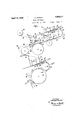
Figure 1 is a sectional, side elevation showing an embodiment of the invention combined with a standard machine of the type referred to;
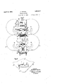
Figure 2 is a plan view of the mechanism illustrated in Figure 1; and
Figure 3 is a plan view of an envelope blank of the type operated upon by the mec anism illustrated, and showin the'blank 1n the condition in which it is de ivered by the novel mechanism to the standard part of the machine.
Referring first to Figure 3, it will be observed that the envelope blank comprises a central body portion 1 having a window opening 2 provided therein and having top and bottom flaps 3 and 4 and side flaps 5 pro ecting therefrom. The novel mechanism of the present blank in the condition described above to apply to the blank a transparent win ow patch 6, and to deliver such blank to the mechanism for. umming the blank and folding it into a finished envelope.
Briefly stated, the operation performed by the illustrated mechanism is as follows: The blanks are placed in a magazine hopper 7,
invention is designed to receive a are withdrawn singly from the bottom of the hopper and are carried by conveying means, past gumming mechanism 8 which applies gum around the window opening, thence past a patch applying mechanism 9, and finally to a second magazine 10 which forms the introductory magazine illustrated in my application referred to above. withdrawn singly from the bottom of this second magazine and are fed through the subsequent instrumentalities of the machine in the usual way for the performance of the subsequent operations upon the blanks.
The magazine 7 comprises upright rods 11 arranged to maintain the blanks in registering stacked form, and supporting means for the stack consisting of oppositely rotating discs 12 and 13. The discs 12 and 13 are The blanks are slotted to form separating fingers 14 and 15 which are arranged to pass between the lowermost blank and the remainder of the stack to segregate such blank from the stack.
As seen in Figures 1 and 2 the bottom flaps of the blanks are turned toward the front of the machine in a position to be operated upon byblank separating mechanism which prepares the lowermost blank for complete separation from the stack by the discs 12 and 13. The forward extremities of the bottom flaps are supported somewhat above the plane of the separator discs by a finger 16 and. the blanks are withdrawn past this finger one by one and swun downward by a reciprocating pneumatic pic er 1.7. After a blank has been thus separated at its forward edge and swung downward, the separating fingers 14 and 15 advance to blank engaging position and perform their separating function. Presser fingers 18 advance to press the separated blank beneath rollers 19 and against the-traveling belt 20 against which the rollers 19 that described in my pending application,
referi ed to above, in that the separator fingers 14 and 15 are cut away at their extremities and made blunt, the inner ends of their leading edges being located to escape engagement wlth the window openings of the envelopes. This obviates all danger of snagging and tearing the envelopes by said fingers.
The conveying belt 20 runs upon a roller 21 and a drum 22. As the blanks pass downwardly around the drum 22 they come under the influence of a second conveyor consisting of a belt 23 which runs upon rollers 24, 25 and 26. This belt serves to grip the blanks to the belt 20 and in cooperation with the drum 22 and the belt 20 inverts the blanks. The belt 23 has its active stretch supported in part by tables 27 and 28, and serves, in conjunction with feed rolls 29 and 30, to conduct the inverted blanks past the gummer 8.
The gummer comprises a um box 31, the lower end of which is closed y a gum transferring roller 32. A roller 33 rotates beneath the roller 32 and carries a raised gum applying segment or die 34, which receives gum from the roller 32 and applies it to the margin of the window opening of an envelope blank at a short distance outward from the edge of such opening. The gummed area is indicated at 35 in Figure 3 and the gum applying die has a gum applying surface of the same shape as the gummed area.
The conveyor belt 23 feeds the gummed blanks onto a short table 36 which extends between a feed roller 37 and a patch applying member 38, and which lies in a groove of the roller 37 with its upper surface substantially tangent to the periphery of such roller. Each blank, while supported on this table, has a window patch applied to it.
A web of window patch material 39 is supplied from a reel 40, being drawn from the reel by feed rollers 41 driven at a peripheral speed such that a patch length of the web is fed for each envelope blank separated from the magazine 7. The web is advanced by rollers 41 between the patch applying member 38 and a severing member 42. The patch applying member 38 makes one complete revolution for each envelope blank separated from the magazine 7 and is equal in circumferential extent to the extent of movement of the conveyor belt 23 occurring in one complete cycle of the blank separating mechanism. The member 38 is provided with radial passages 43 which extend from the periphery of the member 38 and communicate through an axial passage 44 with a source of suction. Immediately following the open ends of the passages 43 in the member 38 provision is made of a cutting blade 45. The mechanism is so timed that as the suction passages 43 come beneath the end of the patch web in position to act upon it, the cutting member 42 in cooperation with the blade 45, severs a charged in the identical patch from the end of the web. The patch is then held to the member 38 by the suction means and is carried around and applied to the gummed envelope blank.
From the table 36 the envelope blank passes between conveyor belts 46 and 47. The former belt runs upon rollers 48, 49 and 50 and partially embraces a drum 51. The belt 47 runs upon a roller 52 and the drum 51. These conveyor belts cooperate to carry the blanks around the drum-51 and thereby to re-invert the blanks so that the patch side is turned downward and the blanks are disposition which they occupied in the magazine 7. The blanks pass from between the belts 46 and 47 across an inclined shelf or table 53 and are delivered one by one into the receiving magazine 10. In this magazine they are re-stacked with the patches turned downward, such arrangement being requisite for roper presentation of the blanks to the su sequent operating mechanisms, such mechanisms of the standard machine being so arranged that they will operate to fold the blanks with the window patches on the inside if the blanks are delivered from the magazine with the window patches turned downward.
The magazine 10 and the separating mechanism for taking the blanks therefrom are, element for element, duplicates of the magazine 7 and the separating mechanism for taking the blanks from the magazine 7. The corresponding elements have accordingly been numbered with corresponding numerals followed by the letter a, and will not be described in detail. The two separating mechanisms operate in unison, so that for each blank delivered to the magazine 10 at the top thereof, a blank is withdrawn from the bottom of the magazine. The conveying mechanism for conducting the blanks away from the magazine 7, however, is operated at such a speed that the blanks are completely separated and spaced from one another so that the may be individually treated in passing beneath the gumming mechanism 8 and the patch applying mechanism 9, whereas the conveying mechanism for conducting the blanks away from the magazine 10 operates at relatively low speed to carry the blanks away in fanned out relation. From the magazine 10 the blanks pass to the mechanism of the standard machine described in my application referred to. Such mechanism comprises a conveyor belt 54 which runs upon a roller 55 and a drum 56. A belt conveyor 56a cooperates with the belt 54 and the drum 56. The blanks are conducted around the drum 56 and onto a drum. 57 in fanned out relation, being carried beneath a gummer 58 for applying gum to the exposed margins of the sealing flaps of the fanned out envelope blanks. From the drum 57 the blanks are delivered to a drying belt 59 and thence conducted to the remaining operating mechanisms of the machine.
While I have described what I believe to be the best embodiment of my invention, I do not wish to be limited to the embodiment shown, but what I desire to secure by Letters Patent is set forth in the appended claims.
What I claim is:
1. In an envelope machine, in combination, means for taking window envelope blanks singly from a stack, mechanism for applying window patches to the upper faces of the blanks, a receivingmagazine, means for conveying the blanks from the patch applying mechanism to the receiving magazine, arranged to invert the blanks to turn them patch side down while they are being conveyed, and means for withdrawing the blanks from said receiving magazine and umming marginal portions of those faces 0 said blanks which are turned downward in said receiving magazine.
2. In an envelope machine, in combination, means for taking window envelope blanks singly from a stack, mechanism for applying window patches to the u per faces of the blanks, a receiving magazine, means for conveying the blanks from the patch applying mechanism and de ositing them patch side down in the top of the receivin magazine, and means for separating and feeding the blanks singly from the bottom of the receiving magazine, and gumming marginal portions of those faces of said blankswhich are turned downward in said receiving magazine.
3. In an envelope machine, in combination, a magazine, se arating means for removing blanks singly rom the bottom of the magazine and inverting them, means for applying patches to the faces of .the blanks turned upward bv such inversion, a second magazine, means for reinverting the blanks and deposit ing them in'stacked formation in the second magazine, separating means for removing blanks singly from the bottom of the second magazine, the second magazine and separating means being of the same construction as the first magazine and separating means referred to, and means for applying gum to the faces of the blanks which were turned downward in the second magazine.
4. In an envelope machine, in combination,
a blank magazine, separating means for withdrawing the blanks singly from the magazine,
conveying means for conducting the withdrawn blanks away from the magazine so rapidly that the blanks are conveyed in spaced relation, means for appl 'ng window patches to the faces of the blan which are turnedupward while they are being so conveyed, the conveying means being arranged to invert the blanks after application of the a second separating means operating in unison with the first, conveying means operating at relatively low speed to conduct the blanks away from the second magazine in fanned out relation, and means for applying gum to the faces of the blanks which were turned downward in the second magazine.
5. In an envelope machine, in combination,
means for feeding envelope blanks past a window patch applying station in spaced, definitely timed relation, means for feeding a window patch web at a rate such that a patch of the desired length may be supplied for each blank, means for severing patches from the web and applying them to the envelope blanks comprising a pair of cutting elements, one of said elements constituting also a rotary patch carrier and being provided with means for holding a patch by suction, and the other being adapted to follow the severed patch for a short distance to assist in accelerating it to the peripheral speed of the patch carrier. 6. In an envelope machine, in combination, means for feeding envelope blanks in definitely timed, spaced relation, a patch carrying and applying member running in engagement with the blanks'and synchronously with the timing thereof, means for feeding a patch web a distance of one patch length for each envelope blank, and means cooperating with the patch carrier in severing patches from the web, and patches to the peripheral speed of the patch carr1er..
7. In a window patch applying mechanism in accelerating the severed for an envelope machine, in combination, a
the peripheral speed of the carrier. 7
8. In a window patch applying mechanism for an envelope machine, in combination means for feedmg a patch web, a cutting and carrying member rotating adjacent the path of the web, said member includin suction means and a severing blade closely ollowing the suction means, and means cooperatin with said blade to sever a patch from the end of the web while the suction means is in position to hold the patch so severed, and following the severed patch for a short distance to positively prevent slipping of the patch relative to the carrier.
In testimony whereof I have aflixed my signature to this specification.
ABRAHAM. NOVICK.
atches, a second magazine into which the lanks are d hveredby the conveying means,
iao
web, and to assist in accelerating the patch to no I
Priority Applications (1)
| Application Number | Priority Date | Filing Date | Title |
|---|---|---|---|
| US319502A US1854217A (en) | 1928-11-15 | 1928-11-15 | Envelope machine |
Applications Claiming Priority (1)
| Application Number | Priority Date | Filing Date | Title |
|---|---|---|---|
| US319502A US1854217A (en) | 1928-11-15 | 1928-11-15 | Envelope machine |
Publications (1)
| Publication Number | Publication Date |
|---|---|
| US1854217A true US1854217A (en) | 1932-04-19 |
Family
ID=23242504
Family Applications (1)
| Application Number | Title | Priority Date | Filing Date |
|---|---|---|---|
| US319502A Expired - Lifetime US1854217A (en) | 1928-11-15 | 1928-11-15 | Envelope machine |
Country Status (1)
| Country | Link |
|---|---|
| US (1) | US1854217A (en) |
Cited By (2)
| Publication number | Priority date | Publication date | Assignee | Title |
|---|---|---|---|---|
| US2890631A (en) * | 1955-06-15 | 1959-06-16 | Smithe Machine Co Inc F L | Attachments for envelope making machines |
| US2895551A (en) * | 1952-12-20 | 1959-07-21 | Electrolux Corp | Apparatus for making container closures |
-
1928
- 1928-11-15 US US319502A patent/US1854217A/en not_active Expired - Lifetime
Cited By (2)
| Publication number | Priority date | Publication date | Assignee | Title |
|---|---|---|---|---|
| US2895551A (en) * | 1952-12-20 | 1959-07-21 | Electrolux Corp | Apparatus for making container closures |
| US2890631A (en) * | 1955-06-15 | 1959-06-16 | Smithe Machine Co Inc F L | Attachments for envelope making machines |
Similar Documents
| Publication | Publication Date | Title |
|---|---|---|
| US3593486A (en) | Method for inserting materials in envelope blanks | |
| US3408908A (en) | Apparatus for applying a plurality of patches to envelope blanks in an envelope making machine | |
| US3628304A (en) | Method of forming envelopes having inserts therein from a moving blank web | |
| US3733982A (en) | Machine for producing self-opening envelopes | |
| US2703043A (en) | Envelope patching apparatus | |
| US2244723A (en) | Envelope machine | |
| US1854217A (en) | Envelope machine | |
| US2126920A (en) | Bag making machine | |
| US1851061A (en) | Process and machine for making envelopes | |
| US2102001A (en) | Manufacture of dry-sealing envelopes | |
| US2259752A (en) | Method of manufacturing duplex bags | |
| US2097301A (en) | Envelope machine | |
| US2770176A (en) | Method and apparatus for making open side envelopes | |
| US2983201A (en) | Method of and apparatus for making envelopes | |
| US2257829A (en) | Method and apparatus for forming windows in blanks for envelopes and other articles | |
| US1878437A (en) | Napkin folder | |
| US3572222A (en) | Attachment for a conventional non-window envelope machine | |
| US2126804A (en) | Machine for making window envelopes | |
| US2920539A (en) | Manufacture of envelopes | |
| US1275788A (en) | Window-envelop machine. | |
| US2191496A (en) | Machinery for making window envelopes | |
| US2037110A (en) | Bag making machine | |
| US1834664A (en) | Roller folding machine for the manufacture of envelopes | |
| US2049483A (en) | Machine for manufacture of window envelopes and like containers | |
| US1268674A (en) | Envelop-machine. |