US1854112A - Beet pulling and cutting apparatus - Google Patents
Beet pulling and cutting apparatus Download PDFInfo
- Publication number
- US1854112A US1854112A US423122A US42312230A US1854112A US 1854112 A US1854112 A US 1854112A US 423122 A US423122 A US 423122A US 42312230 A US42312230 A US 42312230A US 1854112 A US1854112 A US 1854112A
- Authority
- US
- United States
- Prior art keywords
- frame
- machine
- arm
- beets
- pulling
- Prior art date
- Legal status (The legal status is an assumption and is not a legal conclusion. Google has not performed a legal analysis and makes no representation as to the accuracy of the status listed.)
- Expired - Lifetime
Links
- 235000016068 Berberis vulgaris Nutrition 0.000 title description 29
- 241000335053 Beta vulgaris Species 0.000 title description 29
- 238000007599 discharging Methods 0.000 description 3
- 238000006243 chemical reaction Methods 0.000 description 2
- 230000000694 effects Effects 0.000 description 2
- 230000000737 periodic effect Effects 0.000 description 2
- 238000006073 displacement reaction Methods 0.000 description 1
- 230000000717 retained effect Effects 0.000 description 1
- 238000005096 rolling process Methods 0.000 description 1
- 125000006850 spacer group Chemical group 0.000 description 1
Images

Classifications
-
- A—HUMAN NECESSITIES
- A01—AGRICULTURE; FORESTRY; ANIMAL HUSBANDRY; HUNTING; TRAPPING; FISHING
- A01D—HARVESTING; MOWING
- A01D27/00—Machines with both topping and lifting mechanisms
- A01D27/02—Machines with both topping and lifting mechanisms with rigid tools
Definitions
- the present invention relates to a machine adapted for pulling beets from'the ground
- the said machine comprises cutter guides adapted to slide upon the top part of the beets and mounted, together with the stalk-cutting knife, upon a frame or struc ture pivoting upon the main frame of the machine, and balanced in an elastic manner in both directions.
- the beet-pulling blades or shares are extended to the rear by suitable branches which facilitate the ascent of the beets and deliver them upon rotatable paddles or blades actuated by a sprocket wheel which controls all the movements of the ma
- the machme comprises a main .frame con- 1 chine.v 1
- the said blades cooperate with a channel device or separator, in such manner that the beets will be delivered into a bottomless basket disposed at the rear of the machine and consisting of two pivoting side walls, and of a rear wall formed by a vertical rake which is pivoted to the machine frame and is subjected-by means of an arm secured to said frameto a periodic lifting action caused by the said sprocket wheel, in such manner that the beets contained in the said basket will be left on the ground in the form of a ile.
- the front rolling portion consists of a single wheel mounted in a pivotlever.
- the machine frame is also mounted upon a crank axle which can be turned by a lever provided with handle, which is pivotally mounted on the said frame at the front part of the machine and is provided with fastening or locking means; said lever is connected to the vehicle axle by suitable rod and link gear, and it serves to raise the knife-carrying frame.
- the controlling lever can be disposed on the left hand side of the vehicle Within the drivers reach, so that he is enabled at any time and with a small effort, to raise the machine out of action or to allow it to descend for operation, and hence the drivers task is much facilitated.
- Figs. 2 and 20 are plan views of the ma chine at front and rear of the line XX respectively.
- Fig. 3 is a side view. of the beet-separator.
- the said frame also carries, in front of the said support 112, a fork-shaped arm 113 to which are secured suitably inclined guides 114: which make contact with the top part of the beet in order to regulate'the height at which the cutting op- 9 eration is effected.
- a rod 21 which is" pinned or otherwise connected to the arm 72 of a two arm lever 72 473 actuated'by an arm 83 adapted to lift the machine, and thus the knife and its guides
- the accompanying drawings show by way will be raised from the ground when the machine is travelling on the road.
- the frame 110 also carries a cross-piece 115 adapted to bear-by means of a spring 116upon an upper cross bracing member 117 forming part of the main frame: said frame 110 is provided with a rod 118 which guides the said spring and also carries a nut 119, in contact with a spring 120 applied upon the cross-piece 117.
- a separator In the rear of the knife is disposed a separator provided with a gate or grating 121 consisting of vertically spaced parallel rods secured at the left side of the machine and extending across the machine and rearwardly,'the opposite ends of the rods being free and the teeth 65 of a toothed drum 57 being disposed to work through the spacer between the rods.
- a gate or grating 121 consisting of vertically spaced parallel rods secured at the left side of the machine and extending across the machine and rearwardly,'the opposite ends of the rods being free and the teeth 65 of a toothed drum 57 being disposed to work through the spacer between the rods.
- the main frame of the machine is mounted upon a crank aXle 6 1 which is provided with two wheels.
- Two rods are connected to the ends of said axle by arms 82 secured to the latter, and both cooperate at the front of the machine with a shaft 84, termed raising shaft, which is rotatable on the side beams of the vehicle and is bent at right angles at its ends atSht and 84b.
- the said shaft 84 is securel to an operating lever 85 provided with fastening means consisting of a. perforated or toothed quadrant 86 disposed at the front part of the machine, cooperating with a latch 87 controlled by a handle88 which is pivoted upon the lever 85.
- the apparatus is operated in a very simple manner. Any action upon the lever 85 is impartedthrough the axle 8st and the arms 841a and sita) the rods 80 thus obtaining by means of the arms 82 a corresponding rotation of the axle 64., and thus the machine can be raised, or can be lowered for operation, with different degrees in these positions. corresponding to the different positions in which the lever 85 can be held upon its quadrant.
- the rotation of the shaft 8st produces, by means of a finger or stud 81 thereon, the rocking of the arm 83 connected to one arm of the two-arm lever 7273, so that the frame is also raised together with the knife and its guides.
- the finger or stud 81 works in a longitudinal slot in the front end of the arm 83 so that it has a lost motion connection therewith and will move the arm in one or the opposite direction accordingly as it engages the front or rear end of the slot.
- Fig. 1 shows the machine raised. 1f the levers 85 be raised, the arm 88 will be moved forwardly and all of the parts moved correspondingly so that the arch of the axle will be swung downward to lower the working mechanism.
- the stalk-discharging drum 57 is provided with radial pins or teeth 65 disposed in groups of four, superposed in two diametrical perpendicular planes; said drum is driven by two bevel gear wheels 5859 actuated by a ground wheel 37 by means of chains or the like.
- the beets proceed in the first place above the pointed end of a device 127 (Fig. 3) which serves to restore the earth to the furrow which is formed when the beets are drawn out.
- a channel device or leveler 129 On the other side of the machine is mounted a channel device or leveler 129 by which the earth is also brought into the furrow in such manner that the ground is levelled off.
- the basket 89 is bottomless and is drawn along upon the ground; at the sides are the panels or fiaps 125 which are mounted upon pivoting arms 126 and are thus enabled t rise and descend according to the nature of the ground.
- the said basket is closed at the rear by a vertical rake 91 mounted upon a frame 92 which may be raised with a regular and periodic motion as the machine travels forward.
- the said frame 92 is secured to a lever 98 mounted on one arm 941a lever in the vertical plane.
- the said arm 95 is engaged below a worm 96 keyed to the shaft 97 of the wheel 37 which serves as a driving wheel when in contact with the ground.
- the worm 96 effects a horizontal angular displacement of the arm 95 above a guide 100 and towards the gear wheel 38 actuating the disk 40.
- the arm is preferably provided with a roller 123 which is in contact with the guide 100.
- the arm also carries a roller 124 cooperating with a cam 1.02 secured to the gear wheel 39.
- the shaft 9'? drives the worm 96 and hence, by means of the wheel 39, the discharging device 40 which delivers the beets, when pulled up, into the basket 89 which rests upon the ground and serves as a shaking device by which the beets are freed from all adhering earth.
- the beets are collected in the basket 89 in which they are normally retained by the rake 91, mounted on the rocking lever 94 whose arm 95 is engaged with the worm 96.
- the said arm 95 is drawn forward by the screw 96 and thus moves toward the wheel 38 until the cam 102 meets the roller 124, thus separating the said arm from the worm 96 and bringing it below the guide 100, hence pivoting the said rocking lever 94 and lifting the rake 91.
- the beets contained in the basket 89 are thus left in piles on the'ground by the machine, while the arm 95, pivoting at 95a under the action of the spring 103, slides below the guide and resumes its original position on the worm 96, and the rake 91 again drops by its own weight; the cycle again commences, and at'a frequency proportional to the speed of travel of the machine.
- the beets are pulled up and are arranged in piles. and can thus be readily collected, and the beettransporting vehicles are allowed to pass with facility between the piles.
- a rake If in the case of rain, or for other reasons, a rake cannot be used, the said rake is lifted up, and a separator 130 is employed to dispose the beets in line on the ground without mixing them with the stalks.
- a counterweight 124 is movable on the lever 93 carrying the rake, and thus the presQ mounted on said frame; knife guides and a for inclining said axle with reference to the frame; means for fastening said axle in any desired position knife-guides and V a stalkcutting blade mounted on a frame pivoted to the main frame; means connecting said pivoted frame to the device controlling the inclination of said vehicle axle, a separator provided with a grating disposed back of the cutting blade and obliquely with reference to the center line of the machine; a rotatable toothed drum situated back of the said separator; beet-pulling blades; a horizontal rotatable disk carrying curved teeth on its periphery disposed back of the said pulling blades and adapted to receive the beets; a
- a beet-pulling and stalk cutting machine a main frame; a pivoting fork provided with a vehicle wheel mounted at the front part of said frame; a crank axle provided with vehicle wheels and at the rear part of said frame; controlling means for inclining said axle with reference to the frame; means for fastening said axle in any desired position; knife-guides and a stalk-cutting blade mounted on a frame pivoted to the main frame; means connecting said pivoted frame to the device controlling the inclination of said vehicle axle, a separator provided with a grating disposed back of the cutting blade and obliquely with reference to the center line of the machine; a rotatable drum situated back of the said separator; beet-pulling blades; ahorizontal rotatable disk carrying curvedteeth on its periphery disposed back ceive the beets; a separator cooperating with the said disk and adapted to convey the beets to the rear; a bottomless basket dragging upon the ground and adapted
- stalk cutting knife disposed upon a structural mine which is pivotally mounted on the main frame, adjustable elastic means for braking the motion of said structural frame in both directions; a transverse shaft journaled at the back part of the frame; a sprocket wheel keyed to said shaft; beet-pulling blades; a horizontal disk actuated by said transverse shaft and adapted to convey the beets to the rear; two longitudinal members pivoted to the machine frame in the rear of said disk; and a rake having a transverse position at the ends of said longitudinal members.
- a main frame In a beet-pulling and stalk-cutting machine; a main frame; a front wheel and axle element, and a crank axle with wheels both mounted on said frame; knife guides and a stalk cutting knife disposed upon a structural frame which is pivotally mounted on the main frame, adjustable elastic means for braking the motion of said structural frame in both directions; a transverse shaft journaled at the back part of the vehicle frame; a.
Landscapes
- Life Sciences & Earth Sciences (AREA)
- Environmental Sciences (AREA)
- Harvesting Machines For Root Crops (AREA)
Description
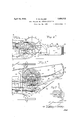
A ril 12, 1932.
F. CUVILLIER 1,854,112
BEET PULLING AND CUTTING APPARATUS Filed Jan. 24, 1930 2 Sheets-Sheet 1 86 o W 85 419 8 8/ /ea f C viZZier'.
April 12, 1932.
F. CUVILLIER BEET PULLING AND CUTTING APPARATUS 2 Sheets-She et 2 Filed Jan. 24, 1930 v w w m W in 1W8 Z W Patented Apr. 12, 1932 U HTE STATES FRANQOIS CIl'VILLIER, OF BAPAUME, FRANCE IBEET PULLING AND CUTTING APPARATUS Application filed. January 24, 1980, Serial No, 45Z{,122, and in France January 29, 1929.
The present invention relates to a machine adapted for pulling beets from'the ground,
cutting off the tops or stalks, and properly arranging the beets and stalks in piles or rows, all ina single operation, in such man ner that the stalks will be discharged to one side and ground will be made level at the furrows produced by the pulling, the beets being also disposed in piles which are regularly spaced and are at a sufficient distance are taken up by a toothed drum and delivapart to allow the transporting'vehicles to circulate between them.
To this effect, the said machine comprises cutter guides adapted to slide upon the top part of the beets and mounted, together with the stalk-cutting knife, upon a frame or struc ture pivoting upon the main frame of the machine, and balanced in an elastic manner in both directions. The stalks or leafyparts ered to an apertured channel device or separator and are then finally discharged to the ground on one side of the machine by animperforate separator. The beet-pulling blades or shares are extended to the rear by suitable branches which facilitate the ascent of the beets and deliver them upon rotatable paddles or blades actuated by a sprocket wheel which controls all the movements of the ma The machme comprises a main .frame con- 1 chine.v 1 The said blades cooperate with a channel device or separator, in such manner that the beets will be delivered into a bottomless basket disposed at the rear of the machine and consisting of two pivoting side walls, and of a rear wall formed by a vertical rake which is pivoted to the machine frame and is subjected-by means of an arm secured to said frameto a periodic lifting action caused by the said sprocket wheel, in such manner that the beets contained in the said basket will be left on the ground in the form of a ile.
Special blades or shares acting at 'the ground level, restore the ear h to the furrow produced by the removal of 'thebeet's, thus leveling off the ground.
To reduce the space required for turning thevehicle about, the front rolling portion consists of a single wheel mounted in a pivotlever. I
Torraise from the ground the various operating devices, the machine frame is also mounted upon a crank axle which can be turned by a lever provided with handle, which is pivotally mounted on the said frame at the front part of the machine and is provided with fastening or locking means; said lever is connected to the vehicle axle by suitable rod and link gear, and it serves to raise the knife-carrying frame.
By this means, the controlling lever can be disposed on the left hand side of the vehicle Within the drivers reach, so that he is enabled at any time and with a small effort, to raise the machine out of action or to allow it to descend for operation, and hence the drivers task is much facilitated.
of example an embodiment of the invention.
Figs. ,1 and laare side views of-the front and rear portions of the machine respectively, the line XX indicating the line of division between the two figures.
Figs. 2 and 20; are plan views of the ma chine at front and rear of the line XX respectively.
Fig. 3 is a side view. of the beet-separator.
rying the cutting knife 26. The said frame also carries, in front of the said support 112, a fork-shaped arm 113 to which are secured suitably inclined guides 114: which make contact with the top part of the beet in order to regulate'the height at which the cutting op- 9 eration is effected. From the frame rises a rod 21 which is" pinned or otherwise connected to the arm 72 of a two arm lever 72 473 actuated'by an arm 83 adapted to lift the machine, and thus the knife and its guides The accompanying drawings show by way will be raised from the ground when the machine is travelling on the road.
The frame 110 also carries a cross-piece 115 adapted to bear-by means of a spring 116upon an upper cross bracing member 117 forming part of the main frame: said frame 110 is provided with a rod 118 which guides the said spring and also carries a nut 119, in contact with a spring 120 applied upon the cross-piece 117.
Thus the movements of the frame 110 are impeded in both directions, and the said frame will rapidly assume its mean position, which latter is adjusted at will by the nut 119. Since the spring 120 supports the weight of the frame 110, it must be stronger than the spring 116.
In the rear of the knife is disposed a separator provided with a gate or grating 121 consisting of vertically spaced parallel rods secured at the left side of the machine and extending across the machine and rearwardly,'the opposite ends of the rods being free and the teeth 65 of a toothed drum 57 being disposed to work through the spacer between the rods.
The leafy parts or stalks are drawn forward by the said drum and are thus delivered upon an imperforate separator 122 which drops them outside of the path of the machine. a
The main frame of the machine is mounted upon a crank aXle 6 1 which is provided with two wheels. Two rods are connected to the ends of said axle by arms 82 secured to the latter, and both cooperate at the front of the machine with a shaft 84, termed raising shaft, which is rotatable on the side beams of the vehicle and is bent at right angles at its ends atSht and 84b. The said shaft 84 is securel to an operating lever 85 provided with fastening means consisting of a. perforated or toothed quadrant 86 disposed at the front part of the machine, cooperating with a latch 87 controlled by a handle88 which is pivoted upon the lever 85.
The apparatus is operated in a very simple manner. Any action upon the lever 85 is impartedthrough the axle 8st and the arms 841a and sita) the rods 80 thus obtaining by means of the arms 82 a corresponding rotation of the axle 64., and thus the machine can be raised, or can be lowered for operation, with different degrees in these positions. corresponding to the different positions in which the lever 85 can be held upon its quadrant.
Since the devices controlling the crank axle are disposed at the front and on the right hand side of the machine, this will much facilitate the control of the machine by the operator who walks at the left hand side of the machine and is enabled, without ceasing to drive his team, to raise or lower at will the rear part of the beet-pulling apparatus according to circumstances.
At the same time, the rotation of the shaft 8st produces, by means of a finger or stud 81 thereon, the rocking of the arm 83 connected to one arm of the two-arm lever 7273, so that the frame is also raised together with the knife and its guides. The finger or stud 81 works in a longitudinal slot in the front end of the arm 83 so that it has a lost motion connection therewith and will move the arm in one or the opposite direction accordingly as it engages the front or rear end of the slot. Fig. 1 shows the machine raised. 1f the levers 85 be raised, the arm 88 will be moved forwardly and all of the parts moved correspondingly so that the arch of the axle will be swung downward to lower the working mechanism.
The stalk-discharging drum 57 is provided with radial pins or teeth 65 disposed in groups of four, superposed in two diametrical perpendicular planes; said drum is driven by two bevel gear wheels 5859 actuated by a ground wheel 37 by means of chains or the like.
On'the main frame are mounted, back of the cutting devices, two beet-pulling blades or shares 32 followed by ramps 11 for the upward travel of the beets, which are thus brought upon a discharging device consisting of a disk 40 provided on its periphery with curved elastic blades 41; said device is rotated from the shaft 97 of the wheel 37 by means of bevel gearing 8889, the bevel gear 38 being secured on the inner end of the shaft 97 and the gear 39 being at the upper end of the shaft of-the disk l0 and meshing with the gear 38 above the shaft 97. The said disk e0 propels the beets along a curved channel 128 leading to a collecting basket 89.
lVhen leaving said pulling blades, the beets proceed in the first place above the pointed end of a device 127 (Fig. 3) which serves to restore the earth to the furrow which is formed when the beets are drawn out.
On the other side of the machine is mounted a channel device or leveler 129 by which the earth is also brought into the furrow in such manner that the ground is levelled off.
The basket 89 is bottomless and is drawn along upon the ground; at the sides are the panels or fiaps 125 which are mounted upon pivoting arms 126 and are thus enabled t rise and descend according to the nature of the ground. The said basket is closed at the rear by a vertical rake 91 mounted upon a frame 92 which may be raised with a regular and periodic motion as the machine travels forward.
For this purpose, the said frame 92 is secured to a lever 98 mounted on one arm 941a lever in the vertical plane. The said arm 95 is engaged below a worm 96 keyed to the shaft 97 of the wheel 37 which serves as a driving wheel when in contact with the ground.
The worm 96 effects a horizontal angular displacement of the arm 95 above a guide 100 and towards the gear wheel 38 actuating the disk 40. To reduce wear, the arm is preferably provided with a roller 123 which is in contact with the guide 100. The arm also carries a roller 124 cooperating with a cam 1.02 secured to the gear wheel 39. A reaction spring 103, attached to the arm 94?) of the rocking lever 94, urges the arm 95 into its initial position (Fig. 2a).
The operationis as follows. When the crank axle 64 is lowered, the apparatus is in the road position, and when travelling, it imparts no motion to the mechanical parts. When the operator uses the lever to lower the arch of the axle and the back part of the apparatus, the wheel 37 makescontact with the ground, and this wheel now serves as a driving wheel due to the travel of the machine, and it thus actuates the shaft 97 upon wh ich it is mounted.
The shaft 9'? drives the worm 96 and hence, by means of the wheel 39, the discharging device 40 which delivers the beets, when pulled up, into the basket 89 which rests upon the ground and serves as a shaking device by which the beets are freed from all adhering earth. The beets are collected in the basket 89 in which they are normally retained by the rake 91, mounted on the rocking lever 94 whose arm 95 is engaged with the worm 96. The said arm 95 is drawn forward by the screw 96 and thus moves toward the wheel 38 until the cam 102 meets the roller 124, thus separating the said arm from the worm 96 and bringing it below the guide 100, hence pivoting the said rocking lever 94 and lifting the rake 91. The beets contained in the basket 89 are thus left in piles on the'ground by the machine, while the arm 95, pivoting at 95a under the action of the spring 103, slides below the guide and resumes its original position on the worm 96, and the rake 91 again drops by its own weight; the cycle again commences, and at'a frequency proportional to the speed of travel of the machine.
Due to these various combinations, the beets are pulled up and are arranged in piles. and can thus be readily collected, and the beettransporting vehicles are allowed to pass with facility between the piles.
If in the case of rain, or for other reasons, a rake cannot be used, the said rake is lifted up, and a separator 130 is employed to dispose the beets in line on the ground without mixing them with the stalks.
A counterweight 124 is movable on the lever 93 carrying the rake, and thus the presQ mounted on said frame; knife guides and a for inclining said axle with reference to the frame; means for fastening said axle in any desired position knife-guides and V a stalkcutting blade mounted on a frame pivoted to the main frame; means connecting said pivoted frame to the device controlling the inclination of said vehicle axle, a separator provided with a grating disposed back of the cutting blade and obliquely with reference to the center line of the machine; a rotatable toothed drum situated back of the said separator; beet-pulling blades; a horizontal rotatable disk carrying curved teeth on its periphery disposed back of the said pulling blades and adapted to receive the beets; a
separator cooperating with said disk and adapted to convey the beets .to the rear; a bottomless basket dragging upon the ground and adapted to receive the beets; and a transverse member vertically movable at the rear end of said basket.
2. In a beet-pulling and stalk cutting machine: a main frame; a pivoting fork provided with a vehicle wheel mounted at the front part of said frame; a crank axle provided with vehicle wheels and at the rear part of said frame; controlling means for inclining said axle with reference to the frame; means for fastening said axle in any desired position; knife-guides and a stalk-cutting blade mounted on a frame pivoted to the main frame; means connecting said pivoted frame to the device controlling the inclination of said vehicle axle, a separator provided with a grating disposed back of the cutting blade and obliquely with reference to the center line of the machine; a rotatable drum situated back of the said separator; beet-pulling blades; ahorizontal rotatable disk carrying curvedteeth on its periphery disposed back ceive the beets; a separator cooperating with the said disk and adapted to convey the beets to the rear; a bottomless basket dragging upon the ground and adapted to receive the beets; and a transverse member vertically movable at the rear end of said basket, a transverse shaft journaled at the back part of the main frame, a sprocket wheel keyed to said shaft, and means by which the said drum and disk may be driven by said wheel.
3. In a beet-pulling and stalk-cutting machine; a main frame; a front wheel and axle element, and a crank axle with wheels, both of the said pulling blades and adapted to re- 111,5
stalk cutting knife disposed upon a structural mine which is pivotally mounted on the main frame, adjustable elastic means for braking the motion of said structural frame in both directions; a transverse shaft journaled at the back part of the frame; a sprocket wheel keyed to said shaft; beet-pulling blades; a horizontal disk actuated by said transverse shaft and adapted to convey the beets to the rear; two longitudinal members pivoted to the machine frame in the rear of said disk; and a rake having a transverse position at the ends of said longitudinal members.
4. In a beet-pulling and stalk-cutting machine; a main frame; a front wheel and axle element, and a crank axle with wheels both mounted on said frame; knife guides and a stalk cutting knife disposed upon a structural frame which is pivotally mounted on the main frame, adjustable elastic means for braking the motion of said structural frame in both directions; a transverse shaft journaled at the back part of the vehicle frame; a. sprocket wheel keyed to said shaft; beetpulling blades; a horizontal disk actuated by said transverse shaft and adapted to convey the beets to the rear; two longitudinal mem bers pivoted to the machine frame in the rear of said disk; a rake having a transverse position at the ends of said longitudinal members, a horizontal pivoted arm carrying the said rake; a worm disposed upon said transverse shaft; an arm secured to the first-mentioned arm as to vertical motion but movable separately in the horizontal direction, and engaged with said worm on the under side of the latter; a cam disposed upon the said transverse shaft, said cam being adapted to release the second-mentioned arm from the worm and to raise the first-mentioned arm vertically; a reaction spring urging the said second arm from the cam; and a guide which prevents said second arm from making contact with said Worm when drawn back by the said spring.
In testimony whereof, I afiix my signature.
FRANQOIS CUVILLIER.
Applications Claiming Priority (1)
| Application Number | Priority Date | Filing Date | Title |
|---|---|---|---|
| FR1854112X | 1929-01-29 |
Publications (1)
| Publication Number | Publication Date |
|---|---|
| US1854112A true US1854112A (en) | 1932-04-12 |
Family
ID=9681682
Family Applications (1)
| Application Number | Title | Priority Date | Filing Date |
|---|---|---|---|
| US423122A Expired - Lifetime US1854112A (en) | 1929-01-29 | 1930-01-24 | Beet pulling and cutting apparatus |
Country Status (1)
| Country | Link |
|---|---|
| US (1) | US1854112A (en) |
-
1930
- 1930-01-24 US US423122A patent/US1854112A/en not_active Expired - Lifetime
Similar Documents
| Publication | Publication Date | Title |
|---|---|---|
| US2337698A (en) | Beet harvester | |
| US1854112A (en) | Beet pulling and cutting apparatus | |
| US2478877A (en) | Beet harvester | |
| US1707878A (en) | Harvester for beans, peas, or the like | |
| US1462486A (en) | Beet-harvesting machine | |
| US1568810A (en) | Beet harvester | |
| US2193205A (en) | Beet topper | |
| US1026835A (en) | Beet-harvester. | |
| US2301158A (en) | Scraper | |
| US2379280A (en) | Grubbing machine | |
| US2691261A (en) | Adjusting means for root harvesters | |
| US1218532A (en) | Beet-harvesting machine. | |
| US937592A (en) | Beet pulling and topping machine. | |
| US1957108A (en) | Beet harvester | |
| US2546411A (en) | Apparatus for digging and harvesting vegetables | |
| US2600992A (en) | Peanut harvester | |
| US998296A (en) | Beet-harvester. | |
| US1067378A (en) | Beet-harvester. | |
| US1211030A (en) | Beet lifting and digging device. | |
| US1902383A (en) | Tractor operated beet loader | |
| US1334605A (en) | Potato-digger | |
| US1248335A (en) | Peanut-digger. | |
| US1339874A (en) | Beet-machine | |
| US1044472A (en) | Beet-harvester. | |
| US2884079A (en) | Apparatus for lifting bulbs, tubers and root plants, particularly beets |