US1854099A - Voluminal feeder for fibrous materials - Google Patents
Voluminal feeder for fibrous materials Download PDFInfo
- Publication number
- US1854099A US1854099A US517346A US51734631A US1854099A US 1854099 A US1854099 A US 1854099A US 517346 A US517346 A US 517346A US 51734631 A US51734631 A US 51734631A US 1854099 A US1854099 A US 1854099A
- Authority
- US
- United States
- Prior art keywords
- apron
- hopper
- delivery
- feeder
- machine
- Prior art date
- Legal status (The legal status is an assumption and is not a legal conclusion. Google has not performed a legal analysis and makes no representation as to the accuracy of the status listed.)
- Expired - Lifetime
Links
- 239000002657 fibrous material Substances 0.000 title description 10
- 239000000463 material Substances 0.000 description 72
- 238000005303 weighing Methods 0.000 description 4
- 238000009960 carding Methods 0.000 description 3
- 241000239290 Araneae Species 0.000 description 2
- 238000010276 construction Methods 0.000 description 2
- 238000000151 deposition Methods 0.000 description 2
- 230000003028 elevating effect Effects 0.000 description 2
- 238000000034 method Methods 0.000 description 2
- 230000000694 effects Effects 0.000 description 1
- 239000000835 fiber Substances 0.000 description 1
- 230000005484 gravity Effects 0.000 description 1
- 230000001788 irregular Effects 0.000 description 1
- 239000002184 metal Substances 0.000 description 1
- 238000012986 modification Methods 0.000 description 1
- 230000004048 modification Effects 0.000 description 1
- 238000012545 processing Methods 0.000 description 1
- 230000000284 resting effect Effects 0.000 description 1
- 238000009827 uniform distribution Methods 0.000 description 1
Images

Classifications
-
- D—TEXTILES; PAPER
- D01—NATURAL OR MAN-MADE THREADS OR FIBRES; SPINNING
- D01G—PRELIMINARY TREATMENT OF FIBRES, e.g. FOR SPINNING
- D01G23/00—Feeding fibres to machines; Conveying fibres between machines
Definitions
- This invention relates to machines for feeding iibrous materials to carding or Garnett machines.
- An automatic feed, for a nett machine, in order to be practical iicient, must deliver the ibrousmaterial, to such machine, in a continuous mass of uniform width and thickness, and of equal density throughout its entire width; and the width of the mass should be substantially the same as the width of the working rolls of the carding or Garnett machine.
- the center of the apron draws a great er quantity of the material from the bulk in the hopper than does the side edges of the elevator apron.
- the material at the center of the apron is of greater density than the material adjacent the side edges of the apron.
- the unequal condition of the material on the elevator apron is further accentuated by the material adjacent the side edges of the apron being retarded by frictional engagement With the side Walls vof the hopper, resulting quite often in the material being removed from various ⁇ places along the side edges of the apron and 'dropping back into the hopper, leaving gaps on the elevator apron.
- the scale may contain the required weight before dumping on the delivery apron of the feeder, the mass of material making up this Weight is to a great extent concentrated at the center of the weigher scoop or hop er.
- the scale deposits the weiglhed mass on the delivery apron of the feeder the center of the delivery apron is overfed, while the edges of the apron are relatively starved.
- the primary object of this invention is to provide an automatic feeder which will present to the take-in rolls of a web-forming machine a mass of fibrous material which will be of uniform thickness and uniform density throughout its entire width and length and the width of the mass will be substantially the same as the width of the take-in rolls of the Web-forming machine, resulting in an ultimate web of uniform thickness and density throughout when removed from the doifers of the web-forming machine.
- the principleupon which this improved feeder is based concerns the depositing of the material on the delivery apron of the feeder according to volume rather than weight.
- the improved feeder comprises a delivery hopper and means for keeping this hopper completely full and the level of the material in the hopper constant from side to side of the ⁇ hopper at all times, thus insuring uniform density of the mass of material in the delivery hopper throughout the entire width of the hopper.
- the delivery hopper is provided, in its preferred form, with two oppositely disposed movable walls which synchronously advance the uniform mass in the hopper toward the delivery apron of the feeder, the delivery apron of the feeder continuously presenting the uniform mass to the take-in rolls of the web-forming machine, all as will be fully disclosed hereinafter, reference being had to the accompanying drawings, of which:
- Fig. 1 is a left hand side elevation of a voluminal feeder ⁇ made in accordance with the principles of the invention
- Fig. 2 is a right hand elevation of the feeder
- Fig. 3 is a longitudinal sectional elevation of the feeder
- Fig. 4 is a fragmentary sectional plan View taken on the line 4.-4, Fig. 3;
- Fig. 5 is a transverse sectional elevation taken on the line 5-5, Fig. 3;
- Fig. 6 is a diagrammatic view, in sectional elevation, showing the delivery hopper as being provided with one movable wall and an oppositely disposed relatively fixed wall and Fig. 7 illustrates another modification in which both opposing walls of the delivery hopper are relatively fixed.
- the feeder comprises left and right hand side walls 1 and 2 respectively, which constitute the main frame of the machine.
- a receiving hopper 3 having side walls 4 and 5 respectively aligned with the side walls 1 and 2.
- the receiving hopper 3 also comprises a front wall 6 extending transversely of the machine from side to side thereof.
- the wall of the receiving hopper disposed opposite to the wall 6 thereof consists of a spiked elevator apron. such as may be found in most automatic feeders, and in the present instance this spiked apron is indicated at 7.
- the bottom of the receiving hopper consists of an apron 8, the upper run 9 of which is adapted tobe moved in the direction of the arrow shown in Fig. 3 to continuously advance, preferably in intermittent steps, the bulk of material in the hopper 3 toward the upwardly moving run 10 of the spiked elevator apron 7.
- The-bottom apron 8 of the receiving hopper 3 comprises suitable laterally spaced endless side chains 11, which respectively support the opposite ends of transversely extending slats 12, which may be in the form of metal angles or in the form of wooden slats provided with suitable spikes projecting outwardly therefrom.
- the endless side chains 11 pass around sprocket wheels 13 and 14 spaced longitudinally of the apron 8, the sprockets 14 being secured to a transversely extending sha-ft l5 mounted in suitable bearings on the side walls 4 and 5 of the hopper 3, while the sprockets 13 are secured to a transversely extending Shaft 16 rotatably mounted in suitable bearings secured to said side walls.
- the bearings for the shafts 15 and 16 may be adjustable longitudinally of the machine to effect longitudinal adjustment of the entire apron 8 relative to the elevating apron 7.
- the elevating apron 7 in the present case, comprises laterally spaced side chains 17 which pass around lower sprockets 18 and upper sprockets 19.
- the side chains 17 respectively function to support and carry the opposite ends of cross bars or slats 20, which are provided with spikes 21.
- the spikes 21 may be of anyof the usual constructions common to automatic feeders.
- the lower sprockets 18 are secured to a transversely extending shaft 22 which is rotatably mounted in suitable bearings adjustably secured in the side frames 1 and 2 of the machine.
- the upper sprockets 19 are secured to a transversely extending shaft 23 which is rotatably mounted in suitable bearings formed on or secured to the side frames l and 2 respectively.
- elevator apron has been described as comprising side chains passing over sprocket wheels and carrying transverse slots, obviouslyy the sprockets may be replaced by plain faced pulleys or rollers and the chains replaced by tapes or a broad canvas belt.
- a wiper apron 25 Disposed adjacent the upper end of the elevator apron 7 is a wiper apron 25, which comprises laterally spaced side chains 26 passing around sprocket wheels 27 and 28 and supporting transverse slat members 29 at their opposite ends which are provided with outwardly extending pins or spikes 30.
- the sprockets 27 are secured to a transversely extending shaft 31 rotatably mounted in suitable bearings adjustably mounted in the side frames 1 and 2 of the machine.
- the sprockets 28 are secured in a transversely ex- I tending vvator apron 7.
- wiper apron may be -re- Obviously this or combing motion placed by a drum or reel having a spiked surface correspondmg to the elevator apron 7 is a the spiked surface of the transverse slats 29.
- the clearing reel 35 comprises laterally spaced spiders 36, crosswise of'which extend rigid blades 37.
- the blades 37 have their outer ends providedwith clearing or wiping ele ⁇ - ments 38, which may be of rigid construction or which may be composed of afrelatively flexible material adapted to clean the fibrous material from the spikes 21, of the elevator apron 7, as the said apron passes.,
- the spiders 36 of the clearer 35 are mounted on and are secured to a transversely extending shaft 39 which is rotatably mounted in suitable bearings carried by the .side frames 1 and 2 of the machine.
- an evener apron 40 which comprises in the present instance a flexible belt or tapes 41, adapted to support slats 42 having spikes 43 extending outwardly therefrom.
- the belt or tapes 41 pass around supporting 45 which are respectively secured to transversely extending shafts 46 and 47.
- the shafts 46 and 47 are rotatably mounted in suitable bearings adjustably carried by the side frames ⁇ l and 2 of the machine.
- the material wiped from the elevator apron 7 by the clearing reel 35 is directed onto the upper run of the evener apron 40 by means of a chute or guide plate 50, which extends between and is supported at its opposite ends by the side frames 1 and 2 of the machine.
- a delivery trough or hopper 55 Disposed below the lower run of the evener apron 40 is.
- the end walls of the delivery hopper are formed by the side walls 1 and 2 of the machine in the present instance, while the front and rear walls 56 and 57 of the said delivery hopper are formed by the down-runs of substantially vertically disposed slatted aprons 58 and 59, the said walls 56 and 57 moving downwardly at the same or relatively different rates of speed to carry the material from the delivery hopper 55 onto the delivery apron 60 ofthe machine.
- the delivery apron 60 after receiving the material inv a flat mass of uniform density and even thickness throughout, from the delivery hopper 55 feeds the material to and between a pair of take-in rolls 61 and 62 of the wheels or rollers 44 andv web-forming machine to which the .feeder is a plied.
- T e a. rons 58 and 59 constituting the front an rear walls 56 and 57 of the hopper 55,*like the evener apron 40, are compose of endless belts or tapes-which function to support transversely extending slats 63. These aprons. pass around suitable supporting wheels or rollers.
- the apron 58 is supported by ⁇ wheels or rollers 64, at Vits -upper end.
- the circular supports 64 are secured to a transversely extending shaft 65.
- the shaft 65 is rotatably mounted. in suitable bearings adjustabl secured to,I the side frames of the mac ine.
- the lower end of the apron 58 passes around supporting rolls or wheels 66 which are secured to a transversely extending shaft 67.
- the shaft 67 is rotatably mounted in suitable bearings on the side frames of the machine.
- the belt 59 at its upper end, p asses laround ,”fvheels or rollers 68 secured to a transversely extending shaft 69 that is rotatably mounted in suitable bearings'on the side frames 1- and 2; and the lower end of the belt 59 passes around similar circular supports 70 secured to a transversely extending shaft 71 which is rotatably mounted in the side frames 1 and 2.
- the delivery apron 60 in the present instance, constitutes a flexible belt or tapes 72 which pass around rollers 7 3 and 74 having trunnions or shafts 75 and 76, respectively, which are rotatably mounted in suitable bearings adjustably carried by the side frames 1 and 2 of the machine.
- the belt or tapes 72 of the delivery apron 60 function to support transversely extending slats 77 on which the material rests as it is delivered from the delivery hopper 5 5.
- the machine is provided with a driving shaft 80, on the one end of which, adjacent the side wall 1 of the machine, is a pulley 81, around which passes one end of a crossed belt 82. The opposite end of said belt passes around a pulley l83 secured to the end of the clearing-reel shaft 39.
- a pinion 84 which meshes with an idler gear 85 rotatably mounted on the side frame 1.
- a gear wheel 86 which is rotatably mounted on a stud 87 adjustably carried by the side frame 1.
- a sprocket wheel 88 Rotatably mounted on the stud 87 and secured to the gear 86, ⁇ for rotation therewith, is' a sprocket wheel 88, around which passes one end of an endless sprocket chain 89, the opposite end of said sprocket chain passing around a sprocket wheel 90 secured to the upper shaft 23 of the elevator apron 7.
- a second sprocket wheel 91 Secured to the shaft 23 of the elevator apron 7 is a second sprocket wheel 91, around which passes a sprocket chain 92.
- the sprocket chain v92 also passes around a sprocket wheel 93, secured to one end of the shaft 31 of the wiper apron 25, and around a I sprocket wheel 94 secured to the shaft 47 of the evener apron 40.
- the sprocket chain 92 passes around a take-up sprocket 95, which is rotatably and adjustably mounted on the side wall 1 of the machine and is adapted to take up slack in the sprocket chain 92 in order that the aprons 7, 25 and 40 may be uniformly operated.
- the bottom apron 8,4of the receiving hopper 3 is adapted to be intermittently moved to advance the material in the hopper, step by step, toward the up run 10 of the elevator apron 7, and for this purpose the lower shaft 22 of the elevator apron 7 is provided with a crank 96, on which is adj ustably mounted, for radial movement to increase or decrease the throw of the crank, one end of a reach rod 97, the opposite end of said rod being connected at 98 to an arm 99, which is pivotally mounted on the shaft 15 of the bottom apron 8. On the arm 99 is pivotally mounted a pawl 100, adapted to engage the teeth of the ratchet wheel 101 which is secured to said shaft 15.
- the aprons, 7, 8, 25 and 40 and the clearing reel 35 are rotated from the shaft 80.
- the aprons 58, 59 and 60 are adapted to be driven from the take-in roll 61 of the web-forming-machine, with which the feeder is associated.
- the shaft 102 of the take-in roll 61 is provided with the sprocket 103, around which passes a sprocket chain 104.
- the sprocket chain 104 also passes around a sprocket wheel 105 secured to the shaft 73 of the delivery apron 60, thence around a sprocket 106 secured to the shaft 69 of the apron 59, thence around a sprocket 107 secured to the shaft 65 of the apron 58, thence around. idler sprockets 108 and 109 returning to the sprocket 103 of the take-in roll 61 of the web-forming machine.
- the delivery hopper is kept filled with the fibrous material to be delivered to the take-in rolls of the web-forming machine by mechanism, entirely independent of the web-forming machine, but the feeding of the material from the delivery hopper of the feeder to the take-in rolls of the web-forming machine is controlled by the web-forming machine itself, in order that the feeding mechanism may be so timed with the rolls of the webforming machine that only the correct amount of material for producing a web of given thickness and density can be fed to the takein rolls of the web-forming machine.
- the operation of the feeding machine is as follows:
- the fibrous material. to be carded or combed is dumped into the receiving hopper 3 of the feeder and is fed toward the elevator apron 7 at a predetermined rate by the bottom apron 8 of the receiving hopper 3, the bulk to that of the apron 7 as it passes around the shaft 23.
- the lower run of the wiper apron 25 raturns this surplus material to the hopper
- the clearing reel 35 wipes the material from the hooks 21 of the apron 7 and carries the said material over the concaved chute 50, deposit-ing the material on the upper run of the evener apron 40.
- the upper run of the evener apron 40 carries the material rearwardly, said apron passing around theshaft 46' and carrying the material therewith, after which the lower run of said conveyer carries the material forwardly over the open upper end of the delivery hopper 55.
- the material drops by gravity from the lower run of the apron 40 into the delivery hopper -55 between the movable side walls 56 and 57 thereof and the end walls 1 and 2, the material dropping down onto the upper run of the delivery apron 60 and thereon building ⁇ up within the delivery hopper 55 until said hopper is filled to a level at or above the upper ends of the aprons l58 and 59. After the hopper 55 has become filled the surplusmaterial is dragged off and over the top of the hopper by the spikes in the lower run of the evener apron 40.
- the hopper 55 is maintained in a full condition, at a predetermined level, at all times, the feeding of the material to the hopper 55 being at a considerably greater rate than the discharge of the material from the delivery hopper 55.
- the spikes of the lower run of the evener apron 40 drag the surplus material over the top of a guard plate 110, which extends around the top of the apron 58, the guard plate 110 forming a part of the transverse wall 111 which lies adjacent the rear face of the down run of the elevator apron 7 .
- the wall 111 merges into a curved boot 112, which is preferably perforated to permit grit and dirt to sift through, and which extends around the bottom end of thel conveyer 7.
- the material is fed from the hopper 55 b, the two downwardly moving runs 56 and 5 of the aprons 58 and 59 respectively, the delivery apron 60 operating below the open bottom of the hopper carrying the material around the underside of the apron 59 and outwardly therefrom to the take-in rolls 61 and 62 of the web-forming machine, the layer of material resting lon the upper run of the delivery apron 60 being maintained at a uniform thickness and uniform density throughout.
- the maximum thickness of the' layer of material on the delivery belt 60 corresponds to the distance between the lowermost part of the apron 59 and the upper surface of the upper run of the delivery apron 60.
- thickness of the layer may be varied in different ways as will be noted hereinafter.
- the apron 58 is operated at a higher rate of speed than the apron 59, for example at a ratio of three to two.
- the machine is provided with a casing comprising a front wall 115, a top wall 116 and a rear wall117 which extends downwardly around'the rear end of the evener apron 40 to form a boot 118, which guides the material from the upper run of thel conveyer 40 to the lower run thereof, the inner edge of the boot 118 being disposed adjacent the upper end of the apron 59.
- the apron 58 which forms the front wall of the hopper 55, may be replaced by a relatively fixed wall 56a, the lower end of which in the present instance is shown as beingpivotally mounted on a bar 120 extending between the side walls 1 and 2 of the machine, while the upper edge is shown as being connected to a transverse bar 121, which is adjustably mounted at its opposite ends in slots 122 formed in the side frames 1 and 2.
- the bar 120 may be adjustably mounted in slots, such as the slots 122, in order that vthe wall 56a may be bodily ⁇ moved toward or away from the down run 57 of the apron 59 which forms the rear- ⁇ wall of the chamber 55.
- Such adjustments of either top or bottom or both edges ofthe front wall of the hopper with respect to the rear wall thereof obviously changes the capacity of the hopper.
- both the front and rear walls 56a and 57a of the hopper 55 may be made relatively xed but adJustable toward and away from each other, in which case the material is delivered gardless of how unevenly the material may be placed in the receiving hopper 3 and taken therefrom by the elevator apron 7, the delivery hopper 55, by virtue of the excessive feeding by the apron 7, will be maintained in a filled condition at a predetermined level at all times, the surplus material being scraped from o the top of the hopper 55 by the evener apron 40.
- This method of feedingv ibrous materials insures a layer of material of uniform thickness and uniform density on the delivery apron 60 at all times, consequently the takein roll 61 and 62 will deliver this uniform layer of material to the rolls of the webduce and deliver a web of combed fibers which will beV of uniform thickness and density throughout its entire width and length.
- the thickness of the web may be varied in several ways including the changing of the relative surface speeds of the aprons 58, 59 and 60 and the changing of the capacity of the delivery hopper 55 by moving its front and rear walls toward or away from each other, or by a combination of both.
- a voluminal feeder for fibrous materials, comprising a delivery hopper open at its top and bottom, and endless delivery apron operable beneath the open bottom of the hopper to carry the material therefrom at a predetermined rate, an evener apron operable across the open top of the hopper in a plane spaced above the open top of the hopper for maintaining the material in the hopper at a 5predetermined level at all times ⁇ a pair of endless aprons constituting oppositely disposed walls of said hopper and adapted to feed the material in the hopper down-v wardly onto said delivery apron and to pack the material in the ho per between the movable sidewalls thereo and means for operating said wall aprons at different speeds to facilitate the transfer of the material from the hopper to the deliveryr apron.
Landscapes
- Engineering & Computer Science (AREA)
- Textile Engineering (AREA)
- Preliminary Treatment Of Fibers (AREA)
Description
Apr 12, 1932. BOKUM"ET AL l,854,099
v VOLUMINL FEEDER FORFIBROUS MATERIALS Filed Feb. 20, 1931 4 Sheets-Sheet l PF' 2 1932- w. F. BoKuM E'r AL 1,854,099
VOLUMINAL FEEDER FOR FIBROUS MATERIALS Filed Feb. 20, 1931 4 Sheets-Sheet 2 y www April 12y 1932.
w. F. BoKUM E'r Al. 1,854,099
VOLUMINAL FEEDER FOR FIBRUS MATERIALS Filed Feb. 20, 1931 4 SlleeLS--Sheel 5 April 12 1932 W. F. BOKUM ET Al. '1,854,099
VOLUMINAL FEEDER FOR FIBROUS MATERIALS Filed Feb. 20,*1931 4 sheets-sheet 4 Panarea Apr. 12', 1932 UNITED STATE-s i I 1,854,099l
lnvrl-:lv'r- OFFICE WILLIAM F. BOKUI, F JENKINTOWN,
SYLVANIA., ASSIGNORS '10 DELPHIA, PENNSYLVANIA, .A
VOLUMINAL FEEDER FR FIBROUS MATERIALS Application led February 20, 1931. Serial No. 517,346. l
This invention relates to machines for feeding iibrous materials to carding or Garnett machines.
An automatic feed, for a nett machine, in order to be practical iicient, must deliver the ibrousmaterial, to such machine, in a continuous mass of uniform width and thickness, and of equal density throughout its entire width; and the width of the mass should be substantially the same as the width of the working rolls of the carding or Garnett machine.
The success or failure of the carding process and apparatus infproducing a final web of even thickness and density throughout depends almost entirely upon the proper functioning of the feeder.
Prior to this invention automatic feeders for Web-forming machines have been provided With a scale or other weighing attachment, whereby a given amount of the fibrous material, determined by weight, is delivered by the weighing attachment to the delivery apron of the feeder, which in turn delivers the material to the take-in rolls of the webforming machine.
While it is possible to obtain accuracy in the quantity of material delivered by such weighing attachments it has been practically impossible to obtain uniform distribution of the weighed material across the entire width of the delivery apron, consequently the density of the mass or layer of material on the delivery apron has been irregular and uneven across the apron.
This dificulty arises primarily in the receiving hopper of the feeder, into which the material is dumped in bulk. Quite often the material is not Idistributed evenly, or approximately so, across the receiving hopper, the greater mass lying usually at or near the center of the hopper. These'automatic feeders are usually provided with an elevator apron which constitutes one wall of the hopper and moves upwardly in a substantially vertical or slightly inclined plane and carrying a portion of the material from one side of the bulk, in the hopper, upwardly for delivery to the weighing attachment. The greater portion of the mass and consequentcarding or AGar-, and efI scale hopper,
ly the greater weight of the bulk most often is disposed at the center of the hopper, consequently the center of the apron draws a great er quantity of the material from the bulk in the hopper than does the side edges of the elevator apron. As a'result of this condition the material at the center of the apron is of greater density than the material adjacent the side edges of the apron.
The unequal condition of the material on the elevator apron is further accentuated by the material adjacent the side edges of the apron being retarded by frictional engagement With the side Walls vof the hopper, resulting quite often in the material being removed from various `places along the side edges of the apron and 'dropping back into the hopper, leaving gaps on the elevator apron.
As a result of these conditions, while the scale. may contain the required weight before dumping on the delivery apron of the feeder, the mass of material making up this Weight is to a great extent concentrated at the center of the weigher scoop or hop er. Thus, when the scale deposits the weiglhed mass on the delivery apron of the feeder the center of the delivery apron is overfed, while the edges of the apron are relatively starved.
Other times the mass Within the scale is concentrated at one side or the other of the leaving the material at the center and the opposite side of the scale hopper much thinner than the place Where the greater amount of material is concentrated.
Obviously when the delivery apron of the feeder presents an uneven mass of material to the take-in rolls of the web-forming machine, such concentration and thinning out of the various portions of the mass as it is received by the take-in rolls will continue throughout the entire combing process ing eifected by the web-forming machine, with a result that the ultimate web, as it is taken from the doers of the web-forming machine, will be proportionately uneven throughout.
The primary object of this invention is to provide an automatic feeder which will present to the take-in rolls of a web-forming machine a mass of fibrous material which will be of uniform thickness and uniform density throughout its entire width and length and the width of the mass will be substantially the same as the width of the take-in rolls of the Web-forming machine, resulting in an ultimate web of uniform thickness and density throughout when removed from the doifers of the web-forming machine.
The principleupon which this improved feeder is based concerns the depositing of the material on the delivery apron of the feeder according to volume rather than weight. The improved feeder comprises a delivery hopper and means for keeping this hopper completely full and the level of the material in the hopper constant from side to side of the` hopper at all times, thus insuring uniform density of the mass of material in the delivery hopper throughout the entire width of the hopper.
The delivery hopper is provided, in its preferred form, with two oppositely disposed movable walls which synchronously advance the uniform mass in the hopper toward the delivery apron of the feeder, the delivery apron of the feeder continuously presenting the uniform mass to the take-in rolls of the web-forming machine, all as will be fully disclosed hereinafter, reference being had to the accompanying drawings, of which:
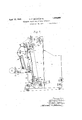
Fig. 1 is a left hand side elevation of a voluminal feeder` made in accordance with the principles of the invention;
Fig. 2 is a right hand elevation of the feeder;
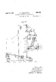
Fig. 3 is a longitudinal sectional elevation of the feeder;
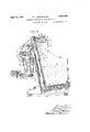
Fig. 4 is a fragmentary sectional plan View taken on the line 4.-4, Fig. 3;
' Fig. 5 is a transverse sectional elevation taken on the line 5-5, Fig. 3;
Fig. 6 is a diagrammatic view, in sectional elevation, showing the delivery hopper as being provided with one movable wall and an oppositely disposed relatively fixed wall and Fig. 7 illustrates another modification in which both opposing walls of the delivery hopper are relatively fixed.
Referring to Figs. 1, 2 and 3 of the drawings, the feeder comprises left and right hand side walls 1 and 2 respectively, which constitute the main frame of the machine. At the front or receiving end of the feeder is provided a receiving hopper 3 having side walls 4 and 5 respectively aligned with the side walls 1 and 2. The receiving hopper 3 also comprises a front wall 6 extending transversely of the machine from side to side thereof.
The wall of the receiving hopper disposed opposite to the wall 6 thereof consists of a spiked elevator apron. such as may be found in most automatic feeders, and in the present instance this spiked apron is indicated at 7.
The bottom of the receiving hopper consists of an apron 8, the upper run 9 of which is adapted tobe moved in the direction of the arrow shown in Fig. 3 to continuously advance, preferably in intermittent steps, the bulk of material in the hopper 3 toward the upwardly moving run 10 of the spiked elevator apron 7.
The-bottom apron 8 of the receiving hopper 3 comprises suitable laterally spaced endless side chains 11, which respectively support the opposite ends of transversely extending slats 12, which may be in the form of metal angles or in the form of wooden slats provided with suitable spikes projecting outwardly therefrom. The endless side chains 11 pass around sprocket wheels 13 and 14 spaced longitudinally of the apron 8, the sprockets 14 being secured to a transversely extending sha-ft l5 mounted in suitable bearings on the side walls 4 and 5 of the hopper 3, while the sprockets 13 are secured to a transversely extending Shaft 16 rotatably mounted in suitable bearings secured to said side walls. Obviously, the bearings for the shafts 15 and 16 may be adjustable longitudinally of the machine to effect longitudinal adjustment of the entire apron 8 relative to the elevating apron 7.
The elevating apron 7, in the present case, comprises laterally spaced side chains 17 which pass around lower sprockets 18 and upper sprockets 19. The side chains 17 respectively function to support and carry the opposite ends of cross bars or slats 20, which are provided with spikes 21. The spikes 21 may be of anyof the usual constructions common to automatic feeders.
The lower sprockets 18 are secured to a transversely extending shaft 22 which is rotatably mounted in suitable bearings adjustably secured in the side frames 1 and 2 of the machine. The upper sprockets 19 are secured to a transversely extending shaft 23 which is rotatably mounted in suitable bearings formed on or secured to the side frames l and 2 respectively.
While the elevator apron has been described as comprising side chains passing over sprocket wheels and carrying transverse slots, obviouslyy the sprockets may be replaced by plain faced pulleys or rollers and the chains replaced by tapes or a broad canvas belt.
Disposed adjacent the upper end of the elevator apron 7 is a wiper apron 25, which comprises laterally spaced side chains 26 passing around sprocket wheels 27 and 28 and supporting transverse slat members 29 at their opposite ends which are provided with outwardly extending pins or spikes 30. The sprockets 27 are secured to a transversely extending shaft 31 rotatably mounted in suitable bearings adjustably mounted in the side frames 1 and 2 of the machine. The sprockets 28 are secured in a transversely ex- I tending vvator apron 7.
wiper apron may be -re- Obviously this or combing motion placed by a drum or reel having a spiked surface correspondmg to the elevator apron 7 is a the spiked surface of the transverse slats 29.
Rotatably mounted adjacent the outer surface of the upper end of the down run 33 of clearing reel 35. The clearing reel 35 comprises laterally spaced spiders 36, crosswise of'which extend rigid blades 37. The blades 37 have their outer ends providedwith clearing or wiping ele`- ments 38, which may be of rigid construction or which may be composed of afrelatively flexible material adapted to clean the fibrous material from the spikes 21, of the elevator apron 7, as the said apron passes.,
around the upper sprockets 19. The spiders 36 of the clearer 35 are mounted on and are secured to a transversely extending shaft 39 which is rotatably mounted in suitable bearings carried by the .side frames 1 and 2 of the machine.
Below the clearer 35 is an evener apron 40 which comprises in the present instance a flexible belt or tapes 41, adapted to support slats 42 having spikes 43 extending outwardly therefrom. The belt or tapes 41 pass around supporting 45 which are respectively secured to transversely extending shafts 46 and 47. The shafts 46 and 47 are rotatably mounted in suitable bearings adjustably carried by the side frames` l and 2 of the machine.
The material wiped from the elevator apron 7 by the clearing reel 35 is directed onto the upper run of the evener apron 40 by means of a chute or guide plate 50, which extends between and is supported at its opposite ends by the side frames 1 and 2 of the machine.
Disposed below the lower run of the evener apron 40 is. a delivery trough or hopper 55, which is adapted to receive the material from the evener apron 40. The end walls of the delivery hopper are formed by the side walls 1 and 2 of the machine in the present instance, while the front and rear walls 56 and 57 of the said delivery hopper are formed by the down-runs of substantially vertically disposed slatted aprons 58 and 59, the said walls 56 and 57 moving downwardly at the same or relatively different rates of speed to carry the material from the delivery hopper 55 onto the delivery apron 60 ofthe machine.
The delivery apron 60 after receiving the material inv a flat mass of uniform density and even thickness throughout, from the delivery hopper 55 feeds the material to and between a pair of take-in rolls 61 and 62 of the wheels or rollers 44 andv web-forming machine to which the .feeder is a plied.
T e a. rons 58 and 59 constituting the front an rear walls 56 and 57 of the hopper 55,*like the evener apron 40, are compose of endless belts or tapes-which function to support transversely extending slats 63. These aprons. pass around suitable supporting wheels or rollers.
lThe apron 58 is supported by `wheels or rollers 64, at Vits -upper end. The circular supports 64 are secured to a transversely extending shaft 65. The shaft 65 is rotatably mounted. in suitable bearings adjustabl secured to,I the side frames of the mac ine. The lower end of the apron 58 passes around supporting rolls or wheels 66 which are secured to a transversely extending shaft 67. The shaft 67 is rotatably mounted in suitable bearings on the side frames of the machine. The belt 59, at its upper end, p asses laround ,"fvheels or rollers 68 secured to a transversely extending shaft 69 that is rotatably mounted in suitable bearings'on the side frames 1- and 2; and the lower end of the belt 59 passes around similar circular supports 70 secured to a transversely extending shaft 71 which is rotatably mounted in the side frames 1 and 2.
The delivery apron 60, in the present instance, constitutes a flexible belt or tapes 72 which pass around rollers 7 3 and 74 having trunnions or shafts 75 and 76, respectively, which are rotatably mounted in suitable bearings adjustably carried by the side frames 1 and 2 of the machine. The belt or tapes 72 of the delivery apron 60 function to support transversely extending slats 77 on which the material rests as it is delivered from the delivery hopper 5 5.
As shown in Fig. 1, the machine is provided with a driving shaft 80, on the one end of which, adjacent the side wall 1 of the machine, is a pulley 81, around which passes one end of a crossed belt 82. The opposite end of said belt passes around a pulley l83 secured to the end of the clearing-reel shaft 39.
Also secured to the drive shaft 80 is a pinion 84 which meshes with an idler gear 85 rotatably mounted on the side frame 1. Meshing with the idler gear 85 isa gear wheel 86, which is rotatably mounted on a stud 87 adjustably carried by the side frame 1. Rotatably mounted on the stud 87 and secured to the gear 86,` for rotation therewith, is' a sprocket wheel 88, around which passes one end of an endless sprocket chain 89, the opposite end of said sprocket chain passing around a sprocket wheel 90 secured to the upper shaft 23 of the elevator apron 7.
Secured to the shaft 23 of the elevator apron 7 is a second sprocket wheel 91, around which passes a sprocket chain 92. The sprocket chain v92 also passes around a sprocket wheel 93, secured to one end of the shaft 31 of the wiper apron 25, and around a I sprocket wheel 94 secured to the shaft 47 of the evener apron 40.
Intermediate the sprockets 91 and 94, the sprocket chain 92 passes around a take-up sprocket 95, which is rotatably and adjustably mounted on the side wall 1 of the machine and is adapted to take up slack in the sprocket chain 92 in order that the aprons 7, 25 and 40 may be uniformly operated.
As shown in Fig. 2, the bottom apron 8,4of the receiving hopper 3, is adapted to be intermittently moved to advance the material in the hopper, step by step, toward the up run 10 of the elevator apron 7, and for this purpose the lower shaft 22 of the elevator apron 7 is provided with a crank 96, on which is adj ustably mounted, for radial movement to increase or decrease the throw of the crank, one end of a reach rod 97, the opposite end of said rod being connected at 98 to an arm 99, which is pivotally mounted on the shaft 15 of the bottom apron 8. On the arm 99 is pivotally mounted a pawl 100, adapted to engage the teeth of the ratchet wheel 101 which is secured to said shaft 15.
From the above it will be seen that the aprons, 7, 8, 25 and 40 and the clearing reel 35 are rotated from the shaft 80. The aprons 58, 59 and 60 are adapted to be driven from the take-in roll 61 of the web-forming-machine, with which the feeder is associated.
The shaft 102 of the take-in roll 61 is provided with the sprocket 103, around which passes a sprocket chain 104. The sprocket chain 104 also passes around a sprocket wheel 105 secured to the shaft 73 of the delivery apron 60, thence around a sprocket 106 secured to the shaft 69 of the apron 59, thence around a sprocket 107 secured to the shaft 65 of the apron 58, thence around. idler sprockets 108 and 109 returning to the sprocket 103 of the take-in roll 61 of the web-forming machine.
By means of these independent drives, the delivery hopper is kept filled with the fibrous material to be delivered to the take-in rolls of the web-forming machine by mechanism, entirely independent of the web-forming machine, but the feeding of the material from the delivery hopper of the feeder to the take-in rolls of the web-forming machine is controlled by the web-forming machine itself, in order that the feeding mechanism may be so timed with the rolls of the webforming machine that only the correct amount of material for producing a web of given thickness and density can be fed to the takein rolls of the web-forming machine.
The operation of the feeding machine is as follows:
The fibrous material. to be carded or combed is dumped into the receiving hopper 3 of the feeder and is fed toward the elevator apron 7 at a predetermined rate by the bottom apron 8 of the receiving hopper 3, the bulk to that of the apron 7 as it passes around the shaft 23. The lower run of the wiper apron 25 raturns this surplus material to the hopper As the material passes over the upper end of the elevator apron 7 and starts downwardly with the down run of the said elevator apron the clearing reel 35 wipes the material from the hooks 21 of the apron 7 and carries the said material over the concaved chute 50, deposit-ing the material on the upper run of the evener apron 40.
The upper run of the evener apron 40 carries the material rearwardly, said apron passing around theshaft 46' and carrying the material therewith, after which the lower run of said conveyer carries the material forwardly over the open upper end of the delivery hopper 55. v
The material drops by gravity from the lower run of the apron 40 into the delivery hopper -55 between the movable side walls 56 and 57 thereof and the end walls 1 and 2, the material dropping down onto the upper run of the delivery apron 60 and thereon building` up within the delivery hopper 55 until said hopper is filled to a level at or above the upper ends of the aprons l58 and 59. After the hopper 55 has become filled the surplusmaterial is dragged off and over the top of the hopper by the spikes in the lower run of the evener apron 40. In this way the hopper 55 is maintained in a full condition, at a predetermined level, at all times, the feeding of the material to the hopper 55 being at a considerably greater rate than the discharge of the material from the delivery hopper 55. Thus it will be seen that regardless of the evenness or the unevenness of the material as it carried up by the elevator apron 7 the hopper will be kept completely filled between the walls 1 and 2 of the machine and the walls 56 and 57 of the hopper.
The spikes of the lower run of the evener apron 40 drag the surplus material over the top of a guard plate 110, which extends around the top of the apron 58, the guard plate 110 forming a part of the transverse wall 111 which lies adjacent the rear face of the down run of the elevator apron 7 .Y Adjacent the bottom of the machine, the wall 111 merges into a curved boot 112, which is preferably perforated to permit grit and dirt to sift through, and which extends around the bottom end of thel conveyer 7.
The material dragged by the lower run of the evener apron 40' from off the top of the material contained within the hopper 55 is caught again by the descending hooks 21 on the down run of the conveyer 7 and carried down along the wall 111 and around the boot 112 into the lower end of the hopper 3.
The material is fed from the hopper 55 b, the two downwardly moving runs 56 and 5 of the aprons 58 and 59 respectively, the delivery apron 60 operating below the open bottom of the hopper carrying the material around the underside of the apron 59 and outwardly therefrom to the take-in rolls 61 and 62 of the web-forming machine, the layer of material resting lon the upper run of the delivery apron 60 being maintained at a uniform thickness and uniform density throughout. f
The maximum thickness of the' layer of material on the delivery belt 60 corresponds to the distance between the lowermost part of the apron 59 and the upper surface of the upper run of the delivery apron 60. The
thickness of the layer may be varied in different ways as will be noted hereinafter.
In order to facilitate the passage of the material around the lower end of the apron 59 from the -hopper 55 on to the delivery `apron 60, the apron 58 is operated at a higher rate of speed than the apron 59, for example at a ratio of three to two.
The machine is provided with a casing comprising a front wall 115, a top wall 116 and a rear wall117 which extends downwardly around'the rear end of the evener apron 40 to form a boot 118, which guides the material from the upper run of thel conveyer 40 to the lower run thereof, the inner edge of the boot 118 being disposed adjacent the upper end of the apron 59.
In some instances, as shown in Fig. 6 for example, the apron 58, which forms the front wall of the hopper 55, may be replaced by a relatively fixed wall 56a, the lower end of which in the present instance is shown as beingpivotally mounted on a bar 120 extending between the side walls 1 and 2 of the machine, while the upper edge is shown as being connected to a transverse bar 121, which is adjustably mounted at its opposite ends in slots 122 formed in the side frames 1 and 2. In some cases, however, the bar 120 may be adjustably mounted in slots, such as the slots 122, in order that vthe wall 56a may be bodily `moved toward or away from the down run 57 of the apron 59 which forms the rear-` wall of the chamber 55. Such adjustments of either top or bottom or both edges ofthe front wall of the hopper with respect to the rear wall thereof obviously changes the capacity of the hopper.
In other instances, such as shown in Fig.
7, both the front and rear walls 56a and 57a of the hopper 55 may be made relatively xed but adJustable toward and away from each other, in which case the material is delivered gardless of how unevenly the material may be placed in the receiving hopper 3 and taken therefrom by the elevator apron 7, the delivery hopper 55, by virtue of the excessive feeding by the apron 7, will be maintained in a filled condition at a predetermined level at all times, the surplus material being scraped from o the top of the hopper 55 by the evener apron 40.
This method of feedingv ibrous materials insures a layer of material of uniform thickness and uniform density on the delivery apron 60 at all times, consequently the takein roll 61 and 62 will deliver this uniform layer of material to the rolls of the webduce and deliver a web of combed fibers which will beV of uniform thickness and density throughout its entire width and length.
The thickness of the web may be varied in several ways including the changing of the relative surface speeds of the aprons 58, 59 and 60 and the changing of the capacity of the delivery hopper 55 by moving its front and rear walls toward or away from each other, or by a combination of both.
In handling light, fluify materials such as staplecotton, etc., it is advisable to spread the walls of the hopper apart, whereas in handling heavier materials. such as secondcut lint, etc., it is advisable to draw the wallsl of the hopper closer together as this heavier material packs more readily than the lighter fluffy materials, thus the thickness of the layer of material may bevaried to suit the requirements.
We claim:
A voluminal feeder, for fibrous materials, comprising a delivery hopper open at its top and bottom, and endless delivery apron operable beneath the open bottom of the hopper to carry the material therefrom at a predetermined rate, an evener apron operable across the open top of the hopper in a plane spaced above the open top of the hopper for maintaining the material in the hopper at a 5predetermined level at all times` a pair of endless aprons constituting oppositely disposed walls of said hopper and adapted to feed the material in the hopper down-v wardly onto said delivery apron and to pack the material in the ho per between the movable sidewalls thereo and means for operating said wall aprons at different speeds to facilitate the transfer of the material from the hopper to the deliveryr apron.
WILLIAM F. BOKUM. JOHN H. SENIOR.
Priority Applications (1)
| Application Number | Priority Date | Filing Date | Title |
|---|---|---|---|
| US517346A US1854099A (en) | 1931-02-20 | 1931-02-20 | Voluminal feeder for fibrous materials |
Applications Claiming Priority (1)
| Application Number | Priority Date | Filing Date | Title |
|---|---|---|---|
| US517346A US1854099A (en) | 1931-02-20 | 1931-02-20 | Voluminal feeder for fibrous materials |
Publications (1)
| Publication Number | Publication Date |
|---|---|
| US1854099A true US1854099A (en) | 1932-04-12 |
Family
ID=24059441
Family Applications (1)
| Application Number | Title | Priority Date | Filing Date |
|---|---|---|---|
| US517346A Expired - Lifetime US1854099A (en) | 1931-02-20 | 1931-02-20 | Voluminal feeder for fibrous materials |
Country Status (1)
| Country | Link |
|---|---|
| US (1) | US1854099A (en) |
Cited By (3)
| Publication number | Priority date | Publication date | Assignee | Title |
|---|---|---|---|---|
| US2744294A (en) * | 1950-01-13 | 1956-05-08 | Curlator Corp | Feeder mechanism for textile machines |
| US2951269A (en) * | 1956-03-23 | 1960-09-06 | Columbia Engineering Company L | Felting method and apparatus |
| US3503532A (en) * | 1967-02-20 | 1970-03-31 | Houget Duesberg Bosson | Apparatus for mixing and automatically emptying cases of fibers or textile materials |
-
1931
- 1931-02-20 US US517346A patent/US1854099A/en not_active Expired - Lifetime
Cited By (3)
| Publication number | Priority date | Publication date | Assignee | Title |
|---|---|---|---|---|
| US2744294A (en) * | 1950-01-13 | 1956-05-08 | Curlator Corp | Feeder mechanism for textile machines |
| US2951269A (en) * | 1956-03-23 | 1960-09-06 | Columbia Engineering Company L | Felting method and apparatus |
| US3503532A (en) * | 1967-02-20 | 1970-03-31 | Houget Duesberg Bosson | Apparatus for mixing and automatically emptying cases of fibers or textile materials |
Similar Documents
| Publication | Publication Date | Title |
|---|---|---|
| US4324495A (en) | Fiber feeder pulley cleaning system | |
| US2703441A (en) | Machine for forming composite fiber webs | |
| US1319190A (en) | van houten | |
| US2053038A (en) | Apparatus for separating and cleaning material | |
| US4499909A (en) | Cigarette manufacturing machine | |
| CH647934A5 (en) | CIGARETTE PACKAGING MACHINE. | |
| US1854099A (en) | Voluminal feeder for fibrous materials | |
| US2702177A (en) | Apparatus for feeding fibrous stock to textile machines | |
| US910812A (en) | Cake-coating machine. | |
| US2166022A (en) | Apparatus for charging cigarette machines with tobacco | |
| US2744294A (en) | Feeder mechanism for textile machines | |
| US1801572A (en) | Machine for applying shredded material to confection-coated wafers and the like | |
| US2833394A (en) | Dual-belt elevator for poultry feeds | |
| US1209880A (en) | Automatic textile receiving and delivering apparatus. | |
| US1777245A (en) | Method of and appratus for cleaning and lapping cotton | |
| CH650651A5 (en) | CIGARETTE PACKING MACHINE WITH AUXILIARY TOBACCO FEEDING UNIT. | |
| US1755081A (en) | Means for loosening and spreading cut tobacco | |
| US2353541A (en) | Compensator for automatic feeds | |
| JPS595271B2 (en) | Hopper for cigarette making machine | |
| CN211771717U (en) | Carding equipment for efficient carding | |
| US2175272A (en) | Automatic powdering machine for thermographic raised printing | |
| US1540417A (en) | Glaze machine | |
| US1514345A (en) | Machine for applying a top coating of comminuted material to confection-coated wafers | |
| US2676361A (en) | Preparatory fiber opener | |
| US5273057A (en) | Cigarette manufacturing machine |