US185408A - Improvement in amalgamating apparatus - Google Patents
Improvement in amalgamating apparatus Download PDFInfo
- Publication number
- US185408A US185408A US185408DA US185408A US 185408 A US185408 A US 185408A US 185408D A US185408D A US 185408DA US 185408 A US185408 A US 185408A
- Authority
- US
- United States
- Prior art keywords
- cylinder
- chamber
- reservoir
- mercury
- ore
- Prior art date
- Legal status (The legal status is an assumption and is not a legal conclusion. Google has not performed a legal analysis and makes no representation as to the accuracy of the status listed.)
- Expired - Lifetime
Links
Images
Classifications
-
- C—CHEMISTRY; METALLURGY
- C22—METALLURGY; FERROUS OR NON-FERROUS ALLOYS; TREATMENT OF ALLOYS OR NON-FERROUS METALS
- C22B—PRODUCTION AND REFINING OF METALS; PRETREATMENT OF RAW MATERIALS
- C22B11/00—Obtaining noble metals
- C22B11/10—Obtaining noble metals by amalgamating
Definitions
- the invention relates to an apparatus by means of which crushed ores. and sand containing free gold or other precious metals are, by their own weight, forced into a column of mercury, and, by mechanical means hereinafter described, thoroughly distributed through the mercury, so that the gold will become, by intimate contact with the mercury, perfectly amalgamated, and conveniently deposited, while the waste is thrown off.
- the invention consists, first, of a cylinder, provided with spurs on its interior surface, and revolving around a stationary post, which may also be provided with similar spurs, for the purpose of facilitating the feeding of the ore or sand to the chamber below; second, of the revolving cylinder, down which the ore is fed,- in combination with a horizontal mixingchamber surrounding the base of the cylinder, and opening into it, the top of such chamber being so formed as to be capable of revolution, and being provided with downwardlyprojecting teeth, which act in connection with corresponding upwardly-projecting teeth upon the bottom of the chamber, for'the purposes hereinafter indicated; third, in combination with the feedin g-cylinder and the mixin g-chamber, an annular reservoir surrounding such chamber and extending above the top thereof, such reservoir being provided with a sunken bottom, depressed below the level of the bottom of the chamber, for the purpose of receiving the deposits of precious metals; fourth, sweeps attached to the upper part of the circular chamber and revolving with it, for
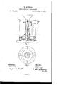
- Figure 1 is a vertical central section
- Fig. 2 is a plan view of the lower part of the same on the line 00 a: of Fig. 1.
- A represents the revolving cylinder, through which the ore is fed to the horizontal mixingchamber below.
- B is a stationary post, around which the cylinder revolves.
- a andb are spurs or projections attached to the cylinder and post.
- 0 O is the top or upper wall of the mixing-chamber.
- D Dis the bottom or lower wall of said chamber.
- 0 and d are teeth attached to the upper and lower walls, and projecting into the chamber.
- E E is the annular reservoir surrounding the lateral chamber.
- 6 e is the outer wall of the reservoir. ffis theinner wall of the same.
- 9 g is the sunken bottom of the reservoir;
- F F sweeps passing over the surface of the mercury in the reservoir.
- h h are spurs or teeth projecting laterally from the perimeter of the upper wall 0 G of the mixingohamber.
- the office of the projections a and b on the cylinder and post is simply to prevent the ore or sand from becoming clogged in its passage down the cylinder. They may be set quartering in the cylinder, or arranged spirally, their office being to stir up the sand or ore, so that it will at all times be free to move down ward.
- the top or upper wall 0 G of the mixingchamber may be attached to the base of the cylinder, and revolves with it, while the entire base of the apparatus, together with the outer rim 6 e of the annular reservoir, may be formed with a single casting, with a socket for the post B in its center.
- the inner rimf f of the annular reservoir may be attached to the upper wall of the mixing-chamber revolving with it, and carrying the sweeps over the surface of the annular reservoir.
- the cylinder, the mixing-chamber, and the annular reservoir are so arranged with relation to each other that there is a free communication between them, so that when the mercury is poured into the annular reservoir it will flow through the mixing-chamber and rise in the base of the cylinder to the same level as in the reservoir.
- the apparatus may be held in position by means of any frame of suitable construction and strength, and revolution may be given to the cylinder and its attachments by means of appropriate pulleys, shafting, and geared wheels, as shown in the drawingin Fig. 1.
- the operation of the apparatus is as follows: Mercury being poured into the annu lar reservoir, flows through the mixing-chamber and rises in the base of the cylinder. The crushedorc or sand is then thrown in at the top of the cylinder A, and the cylinder and its attachments set in revolution. The column of ore in the cylinder must be suflicient'in' height to'overcome the column of mercury in the base of the cylinder. This will be accomplished by the displacement of the mercury by the ore, the mercury being forced up both in the cylinder and the annular reservoir as the ore is forced down into the mercury in the base of the cylinder by its superincumbent weight.
- the constantly increasing weight from above forces the ore laterally into the mixing-chamber, where it is acted on by the teeth attached to the bottom and revolving top of such chamber, being thereby gradually worked out toward the circumference of the chamber and into the annular reservoir, being in its passage through the chamber thoroughly distributed and intimately mixed with the mercury.
- the gold or other precious metals will be deposited in the sunken bottom g g of the reservoir, while the waste, by reason of its less specific gravity, will rise to the surface of the mercury and be thrown off over the outer rim of the reservoir;
- the ore or sand after it has passed through the mixing-chamber, rises up through the annular reservoir it is operated on by the teeth h h projecting from the periphery of the revolving Wall 0 O.
- the function of these revolving teeth is to disintegrate any lumps or masses which may have passed the mixing-chamber, andthns bring thematerial into contact with the mercury Ein;as fine a state of comminution as possible.
- the number of sweeps to be used may be determined by the amount of waste to be disposed of, but enough should be used to keep the surface of the mercury comparatively clear; in practice, very likely two will be found suflieient. If desired, a small quantity of water can be mingled with the ore or sand during its passage down the feeding-cylinder. This may be conveniently accomplished by allowing a small stream to enter the top of the cylinder, where it will at once he brought into contact with the fresh ore.
- the apparatus is continuous in its operation, the ore being constantly supplied to the cylinder and the waste constantly th'rownfrom thetop of the-reservoir.
- Fresh mercury may be supplied :at any time when the mercury in the reservoir becomes too lowfor' successful working.
- the level of the mercury inv the reser-voir should be nearly constant and should rise nearly to the height of the outer wall, so that the waste can be readily swept over the top of the same.
- the mixing-chamber projecting laterally from and surrounding the base of such cylinder, substantially as and for the purpose set forth.
- the annular reservoir having its bottom sunk below the level of the bottom of the mixing-chamber with which it is connected, substantially as set/forth.
Landscapes
- Engineering & Computer Science (AREA)
- Chemical & Material Sciences (AREA)
- Manufacturing & Machinery (AREA)
- Materials Engineering (AREA)
- Mechanical Engineering (AREA)
- Metallurgy (AREA)
- Organic Chemistry (AREA)
- Feeding, Discharge, Calcimining, Fusing, And Gas-Generation Devices (AREA)
Description
W. SLEEPER. A-MALGAMATING APPARATUS. I No.185,408. Patented Dec. 19, 18 76..
THE GRAPH IC CO. N.Y.
UNITED Sra'r s PA ENT WRIGHT SLEEPER, OF (JOATICOOK, QUEBEC, CANADA, ASSIGNOR OF ONE- HALF HIS RIGHT TO EDWIN VAUGHAN, OF GLAREMONT, N. H.
IMPROVEMENT IN AMALGAMATING APPARATUS.
Specificatio-nforming part of Letters Patent No.1 85,408, datedDecember 19, 1876; application filed u February 28, 1876.
:To all whomtt may concern:
. Be it knownthat I, WRIGHT SLEEPER, of Ooaticook, in the county of Stanstead and Dominion of Canada, have invented a new and useful Improvement in Apparatus for Amalgamating and Separating Precious Metals from Foreign Substances, of which the following is a specification:
The invention relates to an apparatus by means of which crushed ores. and sand containing free gold or other precious metals are, by their own weight, forced into a column of mercury, and, by mechanical means hereinafter described, thoroughly distributed through the mercury, so that the gold will become, by intimate contact with the mercury, perfectly amalgamated, and conveniently deposited, while the waste is thrown off.
The invention consists, first, of a cylinder, provided with spurs on its interior surface, and revolving around a stationary post, which may also be provided with similar spurs, for the purpose of facilitating the feeding of the ore or sand to the chamber below; second, of the revolving cylinder, down which the ore is fed,- in combination with a horizontal mixingchamber surrounding the base of the cylinder, and opening into it, the top of such chamber being so formed as to be capable of revolution, and being provided with downwardlyprojecting teeth, which act in connection with corresponding upwardly-projecting teeth upon the bottom of the chamber, for'the purposes hereinafter indicated; third, in combination with the feedin g-cylinder and the mixin g-chamber, an annular reservoir surrounding such chamber and extending above the top thereof, such reservoir being provided with a sunken bottom, depressed below the level of the bottom of the chamber, for the purpose of receiving the deposits of precious metals; fourth, sweeps attached to the upper part of the circular chamber and revolving with it, for the purpose of sweeping over the mercury in the annular reservoir, and throwing the waste off over the outer wall of such reservoir.
The apparatus is illustrated in the accompanying drawing. l
Figure 1 is a vertical central section, and
Fig. 2 is a plan view of the lower part of the same on the line 00 a: of Fig. 1.
Like letters represent like parts in both figures.
A represents the revolving cylinder, through which the ore is fed to the horizontal mixingchamber below. B is a stationary post, around which the cylinder revolves. a andb are spurs or projections attached to the cylinder and post. 0 O is the top or upper wall of the mixing-chamber. D Dis the bottom or lower wall of said chamber. 0 and d are teeth attached to the upper and lower walls, and projecting into the chamber. E E is the annular reservoir surrounding the lateral chamber. 6 e is the outer wall of the reservoir. ffis theinner wall of the same. 9 g is the sunken bottom of the reservoir; F F, sweeps passing over the surface of the mercury in the reservoir. h h are spurs or teeth projecting laterally from the perimeter of the upper wall 0 G of the mixingohamber.
The office of the projections a and b on the cylinder and post is simply to prevent the ore or sand from becoming clogged in its passage down the cylinder. They may be set quartering in the cylinder, or arranged spirally, their office being to stir up the sand or ore, so that it will at all times be free to move down ward.
The top or upper wall 0 G of the mixingchamber may be attached to the base of the cylinder, and revolves with it, while the entire base of the apparatus, together with the outer rim 6 e of the annular reservoir, may be formed with a single casting, with a socket for the post B in its center. The inner rimf f of the annular reservoir may be attached to the upper wall of the mixing-chamber revolving with it, and carrying the sweeps over the surface of the annular reservoir.
The cylinder, the mixing-chamber, and the annular reservoir are so arranged with relation to each other that there is a free communication between them, so that when the mercury is poured into the annular reservoir it will flow through the mixing-chamber and rise in the base of the cylinder to the same level as in the reservoir.
The apparatus may be held in position by means of any frame of suitable construction and strength, and revolution may be given to the cylinder and its attachments by means of appropriate pulleys, shafting, and geared wheels, as shown in the drawingin Fig. 1. Ad-
ditional support, if desired, may be'given to the cylinder by the use of a grooved track carry.-
The operation of the apparatus is as follows: Mercury being poured into the annu lar reservoir, flows through the mixing-chamber and rises in the base of the cylinder. The crushedorc or sand is then thrown in at the top of the cylinder A, and the cylinder and its attachments set in revolution. The column of ore in the cylinder must be suflicient'in' height to'overcome the column of mercury in the base of the cylinder. This will be accomplished by the displacement of the mercury by the ore, the mercury being forced up both in the cylinder and the annular reservoir as the ore is forced down into the mercury in the base of the cylinder by its superincumbent weight. When the ore has been pressed .down to the bottom of the cylinder, the constantly increasing weight from above forces the ore laterally into the mixing-chamber, where it is acted on by the teeth attached to the bottom and revolving top of such chamber, being thereby gradually worked out toward the circumference of the chamber and into the annular reservoir, being in its passage through the chamber thoroughly distributed and intimately mixed with the mercury. When the ore has passed through the chamber and is delivered into the reservoir, the gold or other precious metals will be deposited in the sunken bottom g g of the reservoir, while the waste, by reason of its less specific gravity, will rise to the surface of the mercury and be thrown off over the outer rim of the reservoir; As
the ore or sand, after it has passed through the mixing-chamber, rises up through the annular reservoir it is operated on by the teeth h h projecting from the periphery of the revolving Wall 0 O. The function of these revolving teeth is to disintegrate any lumps or masses which may have passed the mixing-chamber, andthns bring thematerial into contact with the mercury Ein;as fine a state of comminution as possible.
The number of sweeps to be used may be determined by the amount of waste to be disposed of, but enough should be used to keep the surface of the mercury comparatively clear; in practice, very likely two will be found suflieient. If desired, a small quantity of water can be mingled with the ore or sand during its passage down the feeding-cylinder. This may be conveniently accomplished by allowing a small stream to enter the top of the cylinder, where it will at once he brought into contact with the fresh ore.
The apparatus is continuous in its operation, the ore being constantly supplied to the cylinder and the waste constantly th'rownfrom thetop of the-reservoir. Fresh mercury may be supplied :at any time when the mercury in the reservoir becomes too lowfor' successful working. The level of the mercury inv the reser-voir should be nearly constant and should rise nearly to the height of the outer wall, so that the waste can be readily swept over the top of the same.
What is claimed as new is- 1. The revolving feeding-cylinder, provided with spurs or projections, in combination with the central post provided with similar projections, substantially as and for the purpose set forth.
2. In combination, with the revolving feeding-cylinder, the mixing-chamber projecting laterally from and surrounding the base of such cylinder, substantially as and for the purpose set forth.
3. In combination with the mixing-chamber projecting laterally from and surrounding the base of the feedingcylinder, the annular reservoir'surrounding. such chamber, and operating substantially. as set forth.
4. The annular reservoir, having its bottom sunk below the level of the bottom of the mixing-chamber with which it is connected, substantially as set/forth.
5. The revolving sweeps, passing over the surface of the reservoir containing the mercury, for the purpose of removing the waste, substantially as described.
WRIGHT SLEEPER.
Witnesses:
Amos K. Fox, EDWIN VAUGHAN.
Publications (1)
| Publication Number | Publication Date |
|---|---|
| US185408A true US185408A (en) | 1876-12-19 |
Family
ID=2254814
Family Applications (1)
| Application Number | Title | Priority Date | Filing Date |
|---|---|---|---|
| US185408D Expired - Lifetime US185408A (en) | Improvement in amalgamating apparatus |
Country Status (1)
| Country | Link |
|---|---|
| US (1) | US185408A (en) |
-
0
- US US185408D patent/US185408A/en not_active Expired - Lifetime
Similar Documents
| Publication | Publication Date | Title |
|---|---|---|
| US185408A (en) | Improvement in amalgamating apparatus | |
| US45341A (en) | Improved machine for collecting and amalgamating gold and silver | |
| US149127A (en) | Improvement in amalgamators | |
| US211893A (en) | Improvement in apparatus for washing and amalgamating ores | |
| US311258A (en) | David s | |
| US559980A (en) | Rock crushing and grinding apparatus | |
| US58335A (en) | Improved amalgamator | |
| US591119A (en) | Amalgamator | |
| US441867A (en) | Ore-pulverizer | |
| US39240A (en) | Improvement in amalgamators | |
| US30162A (en) | Improvement in quartz pulverizers and amalgamators | |
| US1121537A (en) | Amalgamator. | |
| US561538A (en) | Crushing-mill | |
| US573834A (en) | Amalgamator | |
| US594255A (en) | Portable gold-washer | |
| US208509A (en) | Improvement in amalgamators | |
| US44525A (en) | Improved amalgamator for gold and silver | |
| US537257A (en) | Gold-saving apparatus | |
| US28885A (en) | mills | |
| US393454A (en) | Lead-bath apparatus for working ores | |
| US77259A (en) | Improved apparatus foe disintegrating ores | |
| US29837A (en) | Amalgamator | |
| US211248A (en) | Improvement in amalgamators | |
| US233632A (en) | mahan | |
| US1139143A (en) | Gold-separating mechanism. |