US1854087A - Method of mixing, emulsifying, and blending materials - Google Patents
Method of mixing, emulsifying, and blending materials Download PDFInfo
- Publication number
- US1854087A US1854087A US140344A US14034426A US1854087A US 1854087 A US1854087 A US 1854087A US 140344 A US140344 A US 140344A US 14034426 A US14034426 A US 14034426A US 1854087 A US1854087 A US 1854087A
- Authority
- US
- United States
- Prior art keywords
- rotor
- solids
- materials
- solid
- action
- Prior art date
- Legal status (The legal status is an assumption and is not a legal conclusion. Google has not performed a legal analysis and makes no representation as to the accuracy of the status listed.)
- Expired - Lifetime
Links
- 239000000463 material Substances 0.000 title description 35
- 238000000034 method Methods 0.000 title description 29
- 238000002156 mixing Methods 0.000 title description 24
- 230000001804 emulsifying effect Effects 0.000 title description 5
- 239000007787 solid Substances 0.000 description 55
- 239000007788 liquid Substances 0.000 description 37
- 239000002245 particle Substances 0.000 description 9
- 235000013361 beverage Nutrition 0.000 description 7
- 238000007599 discharging Methods 0.000 description 7
- 239000004615 ingredient Substances 0.000 description 6
- 238000010009 beating Methods 0.000 description 4
- 239000010408 film Substances 0.000 description 4
- 238000003756 stirring Methods 0.000 description 4
- 230000015572 biosynthetic process Effects 0.000 description 3
- 239000000470 constituent Substances 0.000 description 3
- 239000000203 mixture Substances 0.000 description 3
- 238000002360 preparation method Methods 0.000 description 3
- 239000011343 solid material Substances 0.000 description 3
- 210000002105 tongue Anatomy 0.000 description 3
- 241000234295 Musa Species 0.000 description 2
- 235000018290 Musa x paradisiaca Nutrition 0.000 description 2
- 239000011324 bead Substances 0.000 description 2
- 235000013399 edible fruits Nutrition 0.000 description 2
- 239000000839 emulsion Substances 0.000 description 2
- 230000005484 gravity Effects 0.000 description 2
- 239000008267 milk Substances 0.000 description 2
- 210000004080 milk Anatomy 0.000 description 2
- 235000013336 milk Nutrition 0.000 description 2
- 239000012056 semi-solid material Substances 0.000 description 2
- 102100034742 Rotatin Human genes 0.000 description 1
- 101710200213 Rotatin Proteins 0.000 description 1
- 230000006978 adaptation Effects 0.000 description 1
- 235000021028 berry Nutrition 0.000 description 1
- 230000002301 combined effect Effects 0.000 description 1
- 238000006073 displacement reaction Methods 0.000 description 1
- 239000000284 extract Substances 0.000 description 1
- 239000012530 fluid Substances 0.000 description 1
- 235000015203 fruit juice Nutrition 0.000 description 1
- 239000011344 liquid material Substances 0.000 description 1
- 230000002093 peripheral effect Effects 0.000 description 1
- 230000000630 rising effect Effects 0.000 description 1
- 235000014347 soups Nutrition 0.000 description 1
- 238000006467 substitution reaction Methods 0.000 description 1
- 239000000725 suspension Substances 0.000 description 1
- 239000010409 thin film Substances 0.000 description 1
- 235000013311 vegetables Nutrition 0.000 description 1
- 238000005406 washing Methods 0.000 description 1
Images

Classifications
-
- A—HUMAN NECESSITIES
- A47—FURNITURE; DOMESTIC ARTICLES OR APPLIANCES; COFFEE MILLS; SPICE MILLS; SUCTION CLEANERS IN GENERAL
- A47J—KITCHEN EQUIPMENT; COFFEE MILLS; SPICE MILLS; APPARATUS FOR MAKING BEVERAGES
- A47J43/00—Implements for preparing or holding food, not provided for in other groups of this subclass
- A47J43/04—Machines for domestic use not covered elsewhere, e.g. for grinding, mixing, stirring, kneading, emulsifying, whipping or beating foodstuffs, e.g. power-driven
- A47J43/044—Machines for domestic use not covered elsewhere, e.g. for grinding, mixing, stirring, kneading, emulsifying, whipping or beating foodstuffs, e.g. power-driven with tools driven from the top side
- A47J2043/04454—Apparatus of counter top type
- A47J2043/04463—Apparatus of counter top type with a mixing unit rigidly fixed on the housing and a movable support for the bowl
Definitions
- the method of the present invention is intended primarily for use in the commingllng of liquid and solid or semi-solid materials, such as fruits or fruit juices commonly employed in the preparation of beverages or the like, or in the preparation of soups and vegetable extracts for home use, although the process is equally applicable in the commingling of various. materials which it is desir-' milk, as to produce a smooth, creamy and highly desirable beverage.
- the method constitutes an adaptation in the employment of stator and rotor elements, the latter rotating in extremely close proximity to such stator in such a way as to develop a highly efiective centrifugal action which serves to draw down and commingle the admitted particles of liquid and solid or semisolid material, and subject them to the disruptive action of the closely spaced rotating surfaces.
- the solid mate rials such as pieces of banana, or the like, be discharged into the machine in advance of the inflow of the liquid, so that the latter will assist in washing down or carrying forr ward the solid particles which are subjected commin ling by the action of the rotor and stator e ements.
- the present method is directed in particular to the sequence of steps or operations by which the materials are properly discharged into the machine and subjected to the mechanical and centrifugal disintegrating and commingling influences therein developed.
- the present method also makes provision for the reception of the commingled constituent materials discharged from the rotor into a closed receptacle wherein such materials are subjected to the aerating action of the outfiowing air displaced from the receptacle for the purpose of improving the smoothness and quality of the beverage or other mixture, emulsion or blending produced by the employment of the present method.
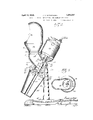
- Figure 1 is a front elevation of the entire machine
- Fig. 2 is a sectional elevation through the center of the entire machine
- Fig. 3 is a cross sectional view taken on line 33 of Fig. 2, looking in the direction of the arrows;
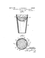
- Fig. 4 is a top view of the receptacle into which the output of the machine is discharged
- Fig. 5 is a sectional elevation of the cup for the discharging of liquid with solid ingredients into the machine.
- Fig. 6 is a top or plan view of the same.
- the machine as a whole is carried by an arch 10 upwardly extending from a circular base 11 which is preferably of sufficiently ponderous formation to stabilize the machine and prevent vibration thereof.
- the center of the arch furnishes a point of attachment for a casing 12 which is configured to afford three points of attachment, respectively, for a motor 13, an inlet dome 14, and a discharge receptacle 15.
- the casing comprises an obliquely extending rear wall .16 which abuts a ainst the forward face of the arch to w ich it may be secured by screws 17 or the like.
- This rear wall as best shown in Fig. 3, is rounded forwardly in respect to the oblique plane through the line of Fig.
- a centrall disposed mixing chamber 18 which merges ownwardly into a rotor chamber 19, the walls 20 of which are outwardly and downwardly flared, as indicated in Fig. 2, to afford a smooth conical surface 21 which constitutes the stator wall and acts in conjunction with a downwardly and outwardly flaring rotor 22 to furnish a restricted annular space 23 between the stator and rotor elements throu h which the materials are fed and directe during the passage through the machine.
- the rotor chamber is of circular cross section at every point, and such cross sectional planes lie in oblique relation to the vertical and intransverse relation to the axis of the rotor which is mounted upon an obliquely disposed shaft 24.
- the conical peripheral wall of the rotor presents its acting outer face to only a portion of the wall of the rotor chamber, the walls of which project both above and below the rotor, the arrangement affording a narrow or relativel restricted inlet to the rotor chamber from the point above, and an enlarged or outwardly flaring outlet below the rotor.
- the side walls 25 of the mixing chamber are rounded outwardly to afford a lateral enlargement or protrusion of the mixin chamber with res ect to the axial line of t e shaft 24.
- the si e walls beyond the protrusion converge forwardl and upwardly, and, in conjunction with t e obliquely dis osed top and bottom walls 26 and 27, aflor an inlet throat for the materials which terminate in an upwardly opening circular mouth 28.
- the shaft 24 1s provided with a lower stir.- ring pin 29 and an upper stirring pin 30, these two pins, in the present instance, being in the form of transversely extending oppositely disposed cotter pins, having their free ends bent or spread in opposite directions.
- the cotter pins thus aflord means for breaking u or disintegrating and stirrin the materials introduced into the mixing c amber, and acting in conjunction with a plurality of pins 31 which extend upwardly from the upper face of the disk shaped rotor element to afford means for fully and complete- 1 stirring, breaking up, and disintegrating t e materials prior to their inflow into the restricted annular space between the rotor and stator where their ultimate breaking up and disintegration is accomplished by the disruptive action of the two contiguous surfaces upon the thin film of liquid under the rate of velocity imparted to the rotor element.
- the motor 13 is mounted upon the upper portion of the casing which presents an obliquely disposed supporting rim 32.
- Ball bearings 33 are provided to reduce friction and maintain the rotor shaft in precise alignment which is necessary in order to maintain the proper clearance between the walls of the rotor and the stator.
- the latter is shouldered at the point 34 which provides a reduced spindle 35 having threads 36 near its lower end, which threads engage with threads 37 on the interior of the hub of the rotor. This permits the rotor to be slid into place until the threads engage, after which a few turns will bring the upper end of the hub into abutment with the shoulder which exactly positions the parts.
- the upwardly opening mouth 28 affords a mounting for the inlet dome 14, the lower end 38 of which is of conical hopper formation terminating in a shouldered ring 39 which may be slipped snugly within the mouth of the inlet throat to hold the dome in vertically upright position.
- the upper portion of the dome is of truly dome shape, and is cut away on one side to afford an oval shaped orifice 40 into which the materials are introduced.
- the orifice is so cut that its upper rim will lie behind the outermost point of projection of its lower rim, and at the same time the orifice is so configured that it will lie in front of the vertical axial plane of the dome, so that the top of the dome will round forwardly and downwardly toward the rim of theorifice in such a way as to furnish an overhangwardly any materials which might be spattered or discharged upwardly when the rotor is in operation.
- the inlet dome is given a configuration somewhat similar to that of a marine ventilator and is rotatable to bring the orifice to the front or to either side as the operator may desire for convenience in operatmg the device.
- the outwardly flaring wall of the rotor chamber affords a mounting for the receptacle 15 which, as shown, is in the form of a tapered cup provided with a flanged rim 41 which seats against a shoulder 42 formed near the mouth of the rotor chamber, the wall bein held in seated position by the action of a p urality of pins 43 which enter into bayonet slots 44 in the rim of the cup.
- These slots are so configured as to. draw the cup forwardly into tightly sealed relation with the shouldered wall of the rotor chamber as the cup is rotatedafter the ins and slots are brought into registering relation.
- the cup is provided through its center with an air outlet tube 45, the upper end 46 of which is flared and terminates at a point in substantially flush relation to the ing hood which will serve to deflect downunder surface 47 is cored outto afford an open passageway from the interior of the cup-- shaped receptacle up and over the flared rim of the tube which permits the air to be displaced from the interior of the receptacle as the mixed prbduct from the machine is discharged thereinto.
- Figs. 5 and 6 illustrate the cup employed for pouring the solid and liquid ingredients into the orificeof the intake dome.
- 47 illus-' trates such cup provided near its upper margin with an outwardly struck bead 48 furnishing a channel for the reception of a plurality of tongues 49 formed around the periphery of a cup shaped strainer plate 50, themargin 51 of which at points. intermediate the tongues 49 is formed to lie slightly out of contact with the surrounding wall of the cup 47.
- the strainer is further provided with a plurality of perforations 52 of suitable size to permit liquid contained in the lower portion of the cup 47 to flow without impediment therefrom, but the strainer serves as a basis for the reception of solid or semi-solid ingredients, such as slices of banana, or other fruits or berries which it is desired to'employ as constituents in a liquid beverage or the like.
- the strainer can be readily removed,' if de-.
- the materials are first lntroduced into the cup 47, the solid portions being suspended within the upper portion of the cup and the liquid ingredients, such as milk, or the like, being poured through and occupying the lower portion of the cup. Thereafter, the operator starts the motor which drives the rotor at a very highv rate of speed, and then poursthe contents of the cup 47 into the orifice in thereceiving dome which will cause the solid portions to be firstdischarged and brought.
- the current flow will be along the side wall adjacent the upper .portion of said figure and down toward the lower or rear edge of the rotor, which direct ing of the line of flow in the spirally converging or hyperbolic line will give positive direction to the infeeding of the materials and beneficially afiectthe operation ofthe machine in the performance of the present method or process.
- the arrangement of the dome is such as to permit the rim of the discharging cup 47 to be inserted into the orifice in the dome in such away as to fill the same during the feeding of "the solid'and liquid materials.
- This closlng of the orifice by the cup additionally guards against any splashingback of the material as it is delivered into the mixing chamber, al-
- the method of mixing liquids and solids comprising subjecting the solids to a rotary beating action to give them an initial disintegration, a'ddin the liquid to the solid while it is being subjected to the rotary beatin action, and then forcing them together in a lm through'a restricted annular passage under the influence of disrupting rotating action, whereby the solid is thoroughly mingled with-and suspended in the liquid.
- a method of mixing liquids and solids com rising initially disintegrating the solids by eating them, adding the liquid to the solids while. they are being thus initially disintegrated, and then subjecting the resulting mixture to a disrupting rotating portionwhereby the thorough commingling of the .1 liquids and solids is completed.
Landscapes
- Engineering & Computer Science (AREA)
- Mechanical Engineering (AREA)
- Food Science & Technology (AREA)
- Non-Alcoholic Beverages (AREA)
- Mixers Of The Rotary Stirring Type (AREA)
Description
April- 12, 1932. J. v. WECVKBAUGH METHOD OF MIXING,
EMULSIFYING, AND BLENDING MATERIALS Filed Oct. 8, 1926 3 Sheets-Sheet April 12, 1932. J v WECKBAUGH 1,854,087
AND BLENDING MATERIALS METHOD OF MIXING, EMULSIFYING,
Filed Oct. 8, 1926 3 Sheets-Sheet 2 April 12, 1932.
J, V. WECKBAUGH METHOD OF MIXING, EMULSIFYING, AND BLENDING MATERIALS Filed 061:. 8, 1926 3 Sheets-Sheet 3 Patented Apr. 12, 1932 UNITED STATES PATENT OFFICE JOSEPH V. WECKIBAUGH, OF NEW YORK, N. Y., ASSIGNOR TO SAMUEL K. NESTEB, OI GENEVA, NEW YORK METHOD OF MIXING, EMULSIFYING, AND BLENDING MATERIALS Application filed October 8, 1926. Serial No. 140,344.
The method of the present invention is intended primarily for use in the commingllng of liquid and solid or semi-solid materials, such as fruits or fruit juices commonly employed in the preparation of beverages or the like, or in the preparation of soups and vegetable extracts for home use, although the process is equally applicable in the commingling of various. materials which it is desir-' milk, as to produce a smooth, creamy and highly desirable beverage.
The above instance is mentioned merely as illustrative of the wide range of usefulness of the present method which is adapted for the preparation of a great many mixtures, emulsions, or blendings of various ingredients, although it is particularly adapted for the commingling of solid or semi-solid lngredients with liqulds. o
The method constitutes an adaptation in the employment of stator and rotor elements, the latter rotating in extremely close proximity to such stator in such a way as to develop a highly efiective centrifugal action which serves to draw down and commingle the admitted particles of liquid and solid or semisolid material, and subject them to the disruptive action of the closely spaced rotating surfaces. In order to prepare the constituent materials for the action of the rotor and stator elements, it is desirable that the solid mate rials, such as pieces of banana, or the like, be discharged into the machine in advance of the inflow of the liquid, so that the latter will assist in washing down or carrying forr ward the solid particles which are subjected commin ling by the action of the rotor and stator e ements.
The present method is directed in particular to the sequence of steps or operations by which the materials are properly discharged into the machine and subjected to the mechanical and centrifugal disintegrating and commingling influences therein developed. The present method also makes provision for the reception of the commingled constituent materials discharged from the rotor into a closed receptacle wherein such materials are subjected to the aerating action of the outfiowing air displaced from the receptacle for the purpose of improving the smoothness and quality of the beverage or other mixture, emulsion or blending produced by the employment of the present method.
Further details of the present method will be apparent from the description thereof as performed in the case of the machine herein illustrated which serves to exemplify the manner in which the various steps of the method are carried out.
In the drawings illustrated- .Figure 1 is a front elevation of the entire machine;
Fig. 2 is a sectional elevation through the center of the entire machine;
Fig. 3 is a cross sectional view taken on line 33 of Fig. 2, looking in the direction of the arrows;
Fig. 4 is a top view of the receptacle into which the output of the machine is discharged;
Fig. 5 is a sectional elevation of the cup for the discharging of liquid with solid ingredients into the machine; and
Fig. 6 is a top or plan view of the same.
The machine as a whole is carried by an arch 10 upwardly extending from a circular base 11 which is preferably of sufficiently ponderous formation to stabilize the machine and prevent vibration thereof. The center of the arch furnishes a point of attachment for a casing 12 which is configured to afford three points of attachment, respectively, for a motor 13, an inlet dome 14, and a discharge receptacle 15. The casing comprises an obliquely extending rear wall .16 which abuts a ainst the forward face of the arch to w ich it may be secured by screws 17 or the like. This rear wall, as best shown in Fig. 3, is rounded forwardly in respect to the oblique plane through the line of Fig. 1 to aflord a centrall disposed mixing chamber 18 which merges ownwardly into a rotor chamber 19, the walls 20 of which are outwardly and downwardly flared, as indicated in Fig. 2, to afford a smooth conical surface 21 which constitutes the stator wall and acts in conjunction with a downwardly and outwardly flaring rotor 22 to furnish a restricted annular space 23 between the stator and rotor elements throu h which the materials are fed and directe during the passage through the machine.
The rotor chamber is of circular cross section at every point, and such cross sectional planes lie in oblique relation to the vertical and intransverse relation to the axis of the rotor which is mounted upon an obliquely disposed shaft 24. The conical peripheral wall of the rotor presents its acting outer face to only a portion of the wall of the rotor chamber, the walls of which project both above and below the rotor, the arrangement affording a narrow or relativel restricted inlet to the rotor chamber from the point above, and an enlarged or outwardly flaring outlet below the rotor.
Referring to Fig. 3, it will be observed that the side walls 25 of the mixing chamber are rounded outwardly to afford a lateral enlargement or protrusion of the mixin chamber with res ect to the axial line of t e shaft 24. The si e walls beyond the protrusion converge forwardl and upwardly, and, in conjunction with t e obliquely dis osed top and bottom walls 26 and 27, aflor an inlet throat for the materials which terminate in an upwardly opening circular mouth 28.
The shaft 24 1s provided with a lower stir.- ring pin 29 and an upper stirring pin 30, these two pins, in the present instance, being in the form of transversely extending oppositely disposed cotter pins, having their free ends bent or spread in opposite directions. The cotter pins thus aflord means for breaking u or disintegrating and stirrin the materials introduced into the mixing c amber, and acting in conjunction with a plurality of pins 31 which extend upwardly from the upper face of the disk shaped rotor element to afford means for fully and complete- 1 stirring, breaking up, and disintegrating t e materials prior to their inflow into the restricted annular space between the rotor and stator where their ultimate breaking up and disintegration is accomplished by the disruptive action of the two contiguous surfaces upon the thin film of liquid under the rate of velocity imparted to the rotor element.
The motor 13 is mounted upon the upper portion of the casing which presents an obliquely disposed supporting rim 32. Ball bearings 33 are provided to reduce friction and maintain the rotor shaft in precise alignment which is necessary in order to maintain the proper clearance between the walls of the rotor and the stator. In order to exactly position the rotor with respect to the shaft, the latter is shouldered at the point 34 which provides a reduced spindle 35 having threads 36 near its lower end, which threads engage with threads 37 on the interior of the hub of the rotor. This permits the rotor to be slid into place until the threads engage, after which a few turns will bring the upper end of the hub into abutment with the shoulder which exactly positions the parts. By providin several rotors differing as to the length of hu substitution can be effected to secure the exact degree of clearance desired between the rotor and stator.
The upwardly opening mouth 28 affords a mounting for the inlet dome 14, the lower end 38 of which is of conical hopper formation terminating in a shouldered ring 39 which may be slipped snugly within the mouth of the inlet throat to hold the dome in vertically upright position. The upper portion of the dome is of truly dome shape, and is cut away on one side to afford an oval shaped orifice 40 into which the materials are introduced. The orifice is so cut that its upper rim will lie behind the outermost point of projection of its lower rim, and at the same time the orifice is so configured that it will lie in front of the vertical axial plane of the dome, so that the top of the dome will round forwardly and downwardly toward the rim of theorifice in such a way as to furnish an overhangwardly any materials which might be spattered or discharged upwardly when the rotor is in operation.
The inlet dome is given a configuration somewhat similar to that of a marine ventilator and is rotatable to bring the orifice to the front or to either side as the operator may desire for convenience in operatmg the device. The outwardly flaring wall of the rotor chamber affords a mounting for the receptacle 15 which, as shown, is in the form of a tapered cup provided with a flanged rim 41 which seats against a shoulder 42 formed near the mouth of the rotor chamber, the wall bein held in seated position by the action of a p urality of pins 43 which enter into bayonet slots 44 in the rim of the cup. These slots are so configured as to. draw the cup forwardly into tightly sealed relation with the shouldered wall of the rotor chamber as the cup is rotatedafter the ins and slots are brought into registering relation.
The cup is provided through its center with an air outlet tube 45, the upper end 46 of which is flared and terminates at a point in substantially flush relation to the ing hood which will serve to deflect downunder surface 47 is cored outto afford an open passageway from the interior of the cup-- shaped receptacle up and over the flared rim of the tube which permits the air to be displaced from the interior of the receptacle as the mixed prbduct from the machine is discharged thereinto.
Figs. 5 and 6 illustrate the cup employed for pouring the solid and liquid ingredients into the orificeof the intake dome. 47 illus-' trates such cup provided near its upper margin with an outwardly struck bead 48 furnishing a channel for the reception of a plurality of tongues 49 formed around the periphery of a cup shaped strainer plate 50, themargin 51 of which at points. intermediate the tongues 49 is formed to lie slightly out of contact with the surrounding wall of the cup 47.
The strainer is further provided with a plurality of perforations 52 of suitable size to permit liquid contained in the lower portion of the cup 47 to flow without impediment therefrom, but the strainer serves as a basis for the reception of solid or semi-solid ingredients, such as slices of banana, or other fruits or berries which it is desired to'employ as constituents in a liquid beverage or the like.
The strainer can be readily removed,' if de-.
sired, by springing the tongues 49 out of contact with the inner channel formed by the bead 48 and readily inserted by areversal of such operation.
In carrying out the method of the present invention with the machine disclosed in the present specification, the materials are first lntroduced into the cup 47, the solid portions being suspended within the upper portion of the cup and the liquid ingredients, such as milk, or the like, being poured through and occupying the lower portion of the cup. Thereafter, the operator starts the motor which drives the rotor at a very highv rate of speed, and then poursthe contents of the cup 47 into the orifice in thereceiving dome which will cause the solid portions to be firstdischarged and brought. into contact with the rapidly rotatin pins, and immediately thereafter the liqui contents will be discharged into the solid ingredients and the entire mass subjected to the disintegrating and comminuting action of the pins and to the centrifugal action of the rotor and ins. The action of the rotating elements Wlll cause the solid particles to be rapidly broken up, and the entire mass will develop a current flow downwardly in a spirally converging direction through the throat and along thewall of the mixing chamber and toward the narrow annular space between the rotor and stator. If the rotor be rotated in a clockwise direc-' tion, as indicated in Fig. 3, the current flow will be along the side wall adjacent the upper .portion of said figure and down toward the lower or rear edge of the rotor, which direct ing of the line of flow in the spirally converging or hyperbolic line will give positive direction to the infeeding of the materials and beneficially afiectthe operation ofthe machine in the performance of the present method or process.
4 The material feeding downwardly through the extremely small space between the rotor and stator surfaces will be subjected to the disruptive efl'ect occasioned by the extremely swift rotation of the rotor which further tears apart the solid or semi-solid particles and reduces them to an extremely fine state of disintegration and at the same time serves to commingle them uniformly throughout the body of the liquid. The'oommingled materials will be discharged from around the lower periphery of the rotor in a sheet having the configuration of a hollow cone which will be driven outwardly against and around the upper wall of the cup. As the material rapidly accumulates in the bottom of the cup, it will replace the air which will be forwarded upwardy and diverted downwardly by thefiaring rim of the air discharge tube, thereby developing air currents which impinge'radi- .ally against the incoming whirling coneshaped sheet of fluid and serve to aerate the same during the brief interval before the 4 air is completely expelled by the filling of the cup. This assists in giving to the beverage, orot-her product of the machine, a creamy consistency which improves its quality as a beverage.
'By placing the axis of the machine on an oblique line with respect to the vertical, andby positioning the receivin dome vertically and arranging its intake ori ce in the manner indicated, the .materials will flow naturally downwardly in a spiral hyperbolic line toward the lower edge of the rotor whose circular direction of movement will continue to carry the material upward in a smooth curve so that the oblique line of flow will be in theform of a smooth spiral curve without sudden breaks or angles. The oblique dispositionof the pins 29, 30, and 31 causes these rotating projections to assume a line of move-,
ment at an angle to the gravity flow of the liquid, and these agencies not only serve to beat up and disintegrate the solid particles but also assist in developing the spiral direction of flow assumed by the material as a re sultant of the action of gravity, of the centrif ugal force, and of the impingement of the pins against the inflowing material. I
The arrangement of the dome is such as to permit the rim of the discharging cup 47 to be inserted into the orifice in the dome in such away as to fill the same during the feeding of "the solid'and liquid materials. This closlng of the orifice by the cup additionally guards against any splashingback of the material as it is delivered into the mixing chamber, al-
though the formation of the dome which furnishes a hood overhanging the orifice will or- I dinarily prevent splashing of the materials even if the cup be not positioned within the orifice.
Although the process of the resent invention has been described particu arly with reference to its applicability for use in the mixing of beverages or the like, the method is equally applicable for use in the industrial arts which presents numerable instances in which it is desirable to commingle liquid and solid or semi-solid particles under the conditions which indicate the applicability of the present method for such purpose.
I claim:
1. The method of commingling liquids and solids and semi-solids which consists in initially segregating'the liquids and solids from one another, sub ecting the solids first and the combined liquids and solids subsequently to a combined centrifugal rotary stirring action to develop a current flow of the com bined materials in a contracting spiral direction, and discharging the commingled materials in the form of an open cone shaped sheet of liquid with the comm-muted solid particles in suspension into a walled space to displace and discharge the air therein contained in the form of air currents impinging against the incoming sheet of combined materials to aerate thesame during the period of displacement and discharge of the air, substan-. tially as described.
2. The method of commingling liquids and solids and semi-solids which consists in initially segregating the liquids and solids or semi-solids from one'another, in feeding the solids in advance of the liquids,subject-ing the commingled liquids and solids or semi-solids to rotative and disintegrating influences directed at an angle to the actionof'g'ravity to c develop a centrifugal and disintegrating action and initially 'commingling the "solid (find liquid particles, feeding the mass through a restricted annular area under the influence of disruptive rotating action and discharging and commingled materials in the'form of a hollow cone shaped sheet into a walled space and displacing the air therein contained by the admission of the commingled materials in such a way as to cause the development of discharging air currents impinging against the incoming sheet of liquid and commingled particles for the.purp'ose of aerating the same, substantially as described. I
3. The method of commingling liquids-and solids or semi-solids which consists in feeding the admitted materials through a restricted annular area, and sub'ecting the same during passage therthroug to a rotative and centrifugal disruptive action, discharging the commin led materials from said space in the form 0 a. hollow cone shaped sheet into a walled space and displacing the air contained therein in such a way as to direct the discharging air in the form of air currents impinging radially against the inner surface of the incoming cone shaped sheet of material for the purpose of aerating the same, substantially as described.
4. The method of mixing liquids and solids comprising subjecting the liquids and solids initially to a spiral motion, subsequently subjecting the liquids and solids to a rotary beating action to give the solids an initial disintegration and then forcing them in a film through a restricted annular area under the influence of disruptive rotating action, whereby the solid is thoroughly mingled with and suspended in the liquid.
5. The method of mixing liquids and solids comprising subjecting them to a rotary beating action'to give the solids an initial disinte-\ gration, and then forcing them in a film through a restricted-annular area under the influence of disruptive rotating action, whereby the solid is thoroughly mingled with and suspended in the liquid.
6. The method of mixing liquids and solids comprising feeding them along a sloping path to a point for subjection to a rotary beat-' ing action to give the solids an initialidisintegration, and then forcing them in a film through a restricted annular passage under the influence of disruptive rotating action, whereby the solid is thoroughly mingled with and suspended in the liquid.
7. The method of mixing liquids and solids comprising imparting to them a spiral motion along a sloping path, subsequently subjecting them to a rotary beating action to give the solids an initial disintegration, and then forcing themin a film through a restricted annular passage under the influence of disruptive rotating action whereby the solid is thorpughgly mingled with and suspended in the 8. The method of mixing liquids and solids comprising subjecting the solids to a rotary beating action to give them an initial disintegration, a'ddin the liquid to the solid while it is being subjected to the rotary beatin action, and then forcing them together in a lm through'a restricted annular passage under the influence of disrupting rotating action, whereby the solid is thoroughly mingled with-and suspended in the liquid.
9. A method of mixing liquids and solids com rising initially disintegrating the solids by eating them, adding the liquid to the solids while. they are being thus initially disintegrated, and then subjecting the resulting mixture to a disrupting rotating portionwhereby the thorough commingling of the .1 liquids and solids is completed.
JOSEPH v. WEGKBAUGH.
Priority Applications (1)
| Application Number | Priority Date | Filing Date | Title |
|---|---|---|---|
| US140344A US1854087A (en) | 1926-10-08 | 1926-10-08 | Method of mixing, emulsifying, and blending materials |
Applications Claiming Priority (1)
| Application Number | Priority Date | Filing Date | Title |
|---|---|---|---|
| US140344A US1854087A (en) | 1926-10-08 | 1926-10-08 | Method of mixing, emulsifying, and blending materials |
Publications (1)
| Publication Number | Publication Date |
|---|---|
| US1854087A true US1854087A (en) | 1932-04-12 |
Family
ID=22490809
Family Applications (1)
| Application Number | Title | Priority Date | Filing Date |
|---|---|---|---|
| US140344A Expired - Lifetime US1854087A (en) | 1926-10-08 | 1926-10-08 | Method of mixing, emulsifying, and blending materials |
Country Status (1)
| Country | Link |
|---|---|
| US (1) | US1854087A (en) |
Cited By (1)
| Publication number | Priority date | Publication date | Assignee | Title |
|---|---|---|---|---|
| US5795062A (en) * | 1996-10-03 | 1998-08-18 | Hamilton Beach/Proctor-Silex, Inc. | Milkshake machine |
-
1926
- 1926-10-08 US US140344A patent/US1854087A/en not_active Expired - Lifetime
Cited By (1)
| Publication number | Priority date | Publication date | Assignee | Title |
|---|---|---|---|---|
| US5795062A (en) * | 1996-10-03 | 1998-08-18 | Hamilton Beach/Proctor-Silex, Inc. | Milkshake machine |
Similar Documents
| Publication | Publication Date | Title |
|---|---|---|
| US4030707A (en) | Blender | |
| RU2328197C2 (en) | Mixing device | |
| JP4744527B2 (en) | Use of mixing device, coffee machine with mixing device and mixing device | |
| TWI442897B (en) | Beverage whipper | |
| US3212757A (en) | Mixing and aerating apparatus | |
| US3606270A (en) | Continuous power blender | |
| US2138468A (en) | Centrifugal separator | |
| US3531092A (en) | Rotary batch mixer and method | |
| CN109068880B (en) | Beverage preparation device | |
| US3140861A (en) | Mixing device | |
| SK132595A3 (en) | Stirring method of pumpable liquid | |
| US3942770A (en) | Device for stirring a liquid | |
| US1854087A (en) | Method of mixing, emulsifying, and blending materials | |
| US1906457A (en) | Means for feeding liquids to centrifugal separator bowls | |
| US1645614A (en) | Agitator | |
| US2515713A (en) | Self-cleaning mixer device | |
| JP2003275102A (en) | Mixing bowl and beverage making device equipped with the same | |
| CN102438756B (en) | continuous running centrifuge | |
| US423285A (en) | Machine for agitating liquids | |
| US1839513A (en) | Machine for disintegrating, mixing, and emulsifying materials | |
| US2143652A (en) | Positively controlled vertical agitator and conditioner | |
| JPS5912711Y2 (en) | Beverage vending machine mixing equipment | |
| US1382765A (en) | Emulsifier | |
| US2553213A (en) | Apparatus for homogenizing liquids | |
| JPH01145030A (en) | Cooker |