US1854076A - Hull extractor for cotton - Google Patents
Hull extractor for cotton Download PDFInfo
- Publication number
- US1854076A US1854076A US455839A US45583930A US1854076A US 1854076 A US1854076 A US 1854076A US 455839 A US455839 A US 455839A US 45583930 A US45583930 A US 45583930A US 1854076 A US1854076 A US 1854076A
- Authority
- US
- United States
- Prior art keywords
- discs
- cotton
- suction
- stripper
- hull
- Prior art date
- Legal status (The legal status is an assumption and is not a legal conclusion. Google has not performed a legal analysis and makes no representation as to the accuracy of the status listed.)
- Expired - Lifetime
Links
- 229920000742 Cotton Polymers 0.000 title description 49
- 238000000638 solvent extraction Methods 0.000 description 17
- 230000015572 biosynthetic process Effects 0.000 description 3
- 238000013459 approach Methods 0.000 description 2
- 230000005484 gravity Effects 0.000 description 2
- 241000606643 Anaplasma centrale Species 0.000 description 1
- 239000000835 fiber Substances 0.000 description 1
- 239000000463 material Substances 0.000 description 1
- 238000005192 partition Methods 0.000 description 1
- 238000000926 separation method Methods 0.000 description 1
- 125000006850 spacer group Chemical group 0.000 description 1
- 239000002699 waste material Substances 0.000 description 1
Images
Classifications
-
- D—TEXTILES; PAPER
- D01—NATURAL OR MAN-MADE THREADS OR FIBRES; SPINNING
- D01B—MECHANICAL TREATMENT OF NATURAL FIBROUS OR FILAMENTARY MATERIAL TO OBTAIN FIBRES OF FILAMENTS, e.g. FOR SPINNING
- D01B1/00—Mechanical separation of fibres from plant material, e.g. seeds, leaves, stalks
- D01B1/02—Separating vegetable fibres from seeds, e.g. cotton
- D01B1/04—Ginning
- D01B1/08—Saw gins
Definitions
- a further object resides in the novel arrangement whereby the cotton is directed against picker discs and carried thereby to a location where the cotton is removed by suction from the discs and delivered into a delivery conduit.
- a further object resides in the novel arrangement whereby independent suction chambers are provided for the cotton and hull exhaust conduits.
- a further object of the invention is to provide a machine for separating hulls from cotton embodying spaced apart picker discs
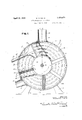
- Figure 1 is a view in side elevation showing one of the side cover plates removed and one of the outside stripper discs removed for showing the arrangement of baffles between the discs.
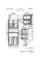
- Figure 2 is a section on line 22of Figure 1.
- Figuresfi and 4 are fragmentary sections on the respectivelines in Figure 1.
- I Figure 5 is a plan view of one ofthe bafl'les and showing the manner in which its side edges arenotched to accommodate the concentrio rows of pickers on the stripper discs.
- Figure 6 is a fragmentary section on line H 6-6 of Figure 1 thru one of the radially extending ribs for directing the cotton against the confronting surfaces of the stripper discs.
- the extractor comprises a cylindrlcal.
- the casingor housing A includes an annular' wall 5 supported upon suitable legs 65 or supports 6. Secured overeach end of the cylindrical shell or annular casing wall 5 as by bolts 7 are removable cover plates 8 in which are axially j ournaled a shaft 9.
- a feed inlet 10 Opening into the:hollow casing thru the v upper portion of the annular wall 5 is a feed inlet 10 thru which the cotton and hulls" are fedinto the casing to be acted upon by the stripper for separation of the cotton from the hulls. Opening tangentially thru the annu- 'lar wall 5 adjacent the lower portion thereof is a hull outlet 11 which maybe connected with any suitable suction device for creating a suction in the casing 5.
- the feed inlet 10 and the'hull outlet 11 are preferably ovalshaped and extend thruout practically the full width of the annular wall 5 as shown in Figure 2.
- a feed conduit or hopper 12 maybe con-- nected with the'casing over the feed inlet opening 10, while a suction pipe 13 is con-. nected with the casing over the hull outlet opening 11.
- the rotatable stripper B comprises a ho1-- 4 low drum-like hub 14 adapted to axially receive the shaft 9 and secured for rotation with the shaft as by a suitable key 15'.
- This hollow hub 14 is provided at each of its flat ends with stripper or ginning discs15 and midway its ends with a. central or medial stripper or ginningdisc 16.
- These discs 15 and 16 form independent annular chambers 17 between the annular casing wall 5 and the hollow hub 14.
- These discs 15 and 16 extend ample shown the end discs 15' are attached to the end walls of the hollow hub 14 while the medial disc '16 is shown formed integral with the hub.
- the end plates 8 are made removable for assembling of the extractor and also to p'ermitinspection of the central disc.
- each end disc 15 Provided upon the innerface ofeach end disc 15 is a series of concentrically arranged rows of picker teeth 18 and these rows of teeth are preferably in the form of saw teeth directed in the direction of rotation of the stripper.
- the rows of picker teeth 18 are also preferably slightly arcuated toward the hub 1 1 as shown in Figures 2 and 3.
- the central or medial disc 16 for co-acting with the end discs 15 is provided at each side with concentrically arranged rows of picker teeth 19 and these teeth 19 are also preferably of saw-like formation and directed in the direction of rotation of the stripper as shown in Figure 1.
- the annular rows of picker teeth 18 are arranged on different diameters from the axis of the hub 1 1 from that of the annular rows of picker teeth 19' and this arrangement has been provided to permit more positive pick-up of the cotton by the teeth during rotation of the stripper.
- cotton fed thru the inlet opening 10 will be divided so that a portion of the cotton will pass into each of the annular chambers 17 between the confronting faces of the end discs 15 and central disc 16.
- each annular chamber 17 Arranged in each annular chamber 17 to extend diagonally beneath the feed inlet opening 10 is a baflie 20 andthese baflles are secured to the inner side of the stationary annular wall 5 at one side of the inlet opening 10.
- These baffles 20 as will be observed Figure 1 extend diagonally across the annular rows of picker teeth and act to direct the cotton entering the opening 10 in a direction counter to the direction of rotation of the picker teeth.
- the b-alfles are slotted at each edge as at 21 toaccommodate the rows of picker teeth and these slots will permit the cotton to be drawn thru the slots by the teeth.
- a hull baffle 22 Projecting into each annular chamber 17 at the outlet opening 11 is a hull baffle 22 which is also slotted along its edges to accommodate the annular rows of picker teeth. These baffles 22 are secured to the annular wall '5 and the upper side of the outlet opening 11 and serve to direct the hulls and other waste matter thru the suction pipe 13.
- the baffles 20 and 22 as will be observed have their inner ends extended into close proximity to the circumference of the hollow hub 14.
- each annular chamber 17 between the balfles 20 and 22 Arranged in each annular chamber 17 between the balfles 20 and 22 is a series of radially extending guide blades 24 of angle or channel shape in. cross section providing angular guide faces 25. These radial guide blades 24 are secured at their outer ends as by bolts or the like 26 to the stationary annular casing wall 5 and have their inner ends extending into close proximity with the circumference of the hub 1d. These radial guide blades 24: are adapted to direct the cotton against the stripper discs so as to be picked up by the annular rows of picker teeth 18 and 19 and carried to the suction extractor means C.
- the material will fall partially by gravity and be directed against the upper guide blade by the inclined baffle 20, and further be directed in a direction counter to the direction of rotation of the stripper by the suction created thru the pipe 13.
- the hulls and cotton are constantly directed against the picker teeth by the angular guide faces 25. The cotton will be picked up by the teeth and carried back to the suction extractor means while the hulls will be'drawn by suction thru the pipe 13.
- a partitioning baffle 30 Projecting radially into each annular chamber 17 from. the annular casing wall 5 to the hub 14 at locations between the hull baffle 22 and suction extractor means B is a partitioning baffle 30.
- These radially extending baffles 30 are secured to the annular casing wall 5 and embody frames 31 supporting bristles 32 which project beyond the side edges and inner ends of the frames into contact with the stripper discs and the hub 14 as clearly shown in Figure 3.
- Thesepartitioning baffles 30 are for dividing the succreated by the means C and outlet pipe 13 so that the hulls will be prevented from entering thesuction operated cotton extractor means C.
- the same embodies a pair of elongated nozzles 34 arranged one in each of the chainbers 17 and connected by suction pipes 35 to a dellvery pipe or tube 36 for conveying the cotton to any desired point by means of suction created thru the pipe 36.
- the suction nozzles 34% are of novel and specific formation and are arranged with their longitudinal axes extending radially of the stripper and slightly to the rear-of the reflector baffle 20.
- the nozzles are of Y- shape in crosssection forming forwardly diverging branch ducts 38 opening along each forward longitudinal edge of the nozzle and forming suction slots 10 extending thru- Ti out thelength of the nozzles.
- the nozzles 34- at their forward wider ends are of a width slightly less than the spacing between the picker teeth 18 and 19 in each chamber 17 so that one of the suction slots 10 is disposed closely adjacent the teeth of one disc while the companion suction slot of the nozzle is disposed closely adjacent the companion confronting teeth.
- the suction slots 10 will be observed extend in directions radially pipe 35 extended thru wall 5.
- the machine has been shown constructed with two annular extractor chambers it will readily be apparent that the machine may be constructed with one or any desired number of the annular extractor chambers. It is also to be understood that the stripper discs may be provided with any preferred type of ginning surfaces and need not necessarily be provided with the concentrically rows of saw-like picker teeth for car rying the cotton to the suction nozzles.
- the picker teeth on the medial stripper disc '16 be'slightly arcuated in an opposition direction to that of the picker teeth on the end discs 15 for more effectively picking up the cotton.
- the bristles 32 have wiping contact with the stripper discs and permit passage of the picker teeth past the partitioning baffles. This wiping contact of the bristles with the stripper disc prevents likelihood of any hulls being drawn past the partitioning baffles by the suction of the cotton suction nozzles 34.
- a cylindrical casing having a radially extending feed inlet opening adjacent its upper side and a suction outlet opening at its lower side, a stripper revolubly mounted in the casing including spaced stripper discs having confronting picker surfaces, a suction nozzle between the discs at one side of the inlet opening, a bafiie extended diagonally beneath the inlet opening between the discs,
- a stripper revolubly mounted in the casing including a hub portion providingan annular chamber and stripper discs having confronting picker surfaces, a baffle carried by the casing and extending between the discs to the hub, said baffle extended diagonally below the inlet opening, a suction nozzle extended between the stripper discs andhav ing suction slots in close proximity to the picker surfaces of the discs, a second baffle carried by the casing at the suction outlet opening and extending between the discs to the hub, and a partitioning baffle carried by the casing and extended between the discs in wiping contact therewith at a location between the suction outlet opening and said suctionnozzle.
- baffle carriedby the casing and extending between the discs to the hub, said baffle extended diagonally below the inlet opening, a suction noz- V zle' extended below the stripper discs and having suction slots in close proximity to the picker surfaces of the discs, a second baffle carriedby the casing at the suction outlet opening and extending between the discs to the hub, means carried by the casing and extending between the stripper discs for directing the cotton against the picker surr uv faces, and a partitioning baflie carried by the casing and extended between the strip-per discs to said hub at a location between the suction outlet opening and said nozzle.
- a stripper revolubly mounted in the casing including a hub portion and stripper discs providing an annular chamber, said stripper discs having confronting picker surfaces, a feed bafile secured at one end to the casing and extending between the stripper discs diagonally beneath the feed inlet, a hull baffie secured to the casing and extending between the discs above the hull suction outlet, a partitioning baiilc carried by the casing and extending between the discs closely adj acent the hull battle, a cotton suction nozzle supported between the discs at a location between-the partitioning bave andfeed bafi'le and having elongated suction slots opening closely adjacent the picker surfaces of each disc, and a series of guide blades carried by the casing and extending in a radial direction between the stripper discs for
- a hull extractor of the class described comprising a cylindrical casing, having a feed inlet opening at its upper side and a hull outlet opening adjacent its lower side, a suction pipe connected with the outlet opening, a
- stripper revolubly mounted in the cylindrical casing including a hub portion and spaced apart stripper discs providing an annular chamber about the hub portion, a series of concentrically arranged rows of picker teeth provided on the confronting surfaces of the stripper discs, a feed battle extended between the discs and the feed inlet opening and having notched sides accommodating the picker teeth, a hull baffle extending between the discs at the outlet opening and having notched sides accommodating the picker teeth, a partitioning baffle extended between the discs at a location between the feed and hull baffles and having yieldable edges in wiping contact with the discs and said hub, radially extending guide blades arranged between the discs for directing the cotton against the picker teeth, and a suction nozzle arranged between the discs at a location between the feed baffle and partitioning baffie and having suction slots for removing the cotton from the picker teeth.
- a hull extractor of the class described comprising a cylindrical casing, having a feed inlet opening at its upper side and a hull outlet opening adjacent its lower side, a suction pipe connected with the outlet opening, a stripper revolubly mounted in the cylindrical casing including a hub portion and spacer apart stripper discs providing an annular chamber about the hub portion, a series of concentrically arranged rows of picker teeth provided on the confronting surfaces of the stripper discs, a feed baffle extended between the discs and the feed inlet opening and having notched sides accommodating the picker teeth, a hull baflle extending between the discs at the outlet opening and having notched sides accommodating the picker teeth, a partitioning bave extended between the discs at a location between the feed and hull bafiies and having yieldable edges in wiping contact with the discs and said hub, radially extending guide blades arranged between the discs for directing the cotton against the picker teeth, and a suction nozzle extending in a radial
- a cylindrical casing having a feed inlet opening at its upper side and a hull outlet opening adjacent its lowerside, a suction pipe connected with the hull outlet opening, a stripper revolubly mounted in the casing including a hub portion, end stripper discs and a medial stripper disc, said discs providing independent annular chambers about the hub portion, annular rows of concentrically arranged picker teeth projecting from the inner surface of each end disc, annular rows of concentrically arranged picker teeth projecting from each face of the medial disc, said feed inlet opening and hull outlet opening having communication with both of said annular chambers, a feed baffle arranged in each annular chamber beneath the feed inletopening, a hull baffle extending into each annular chamber at the hull outlet opening, a series of radially extending guide blades projecting into each annular chamber between the feed and hull baffles for directing the cotton against the picker teeth, a partitioning baflle arranged
- a hull extractor for cotton comprising a cylindrical casing including an annular wall and side cover plates, a feed inlet opening thru the annular wall at the upper side of the casing, a hull outlet opening thru the annular wall adjacent the lower wall of the casing, a suction pipe connected with the outlet opening, a shaft rotatable axially in the cover plate, a stripper rotatable in the casing and fixed upon said shaft, said stripper including a hollow hub portion, a stripper disc secured to each end of the hub and having picker surfaces at their confronting sides,
- a medial disc carried centrally of the hub and having picker surfaces at each side thereof for co-acting with the picker surfaces of the end discs, said end and medial discs forming annular chambers about the hub, a feed bafile carried by the annular casing wall at one side of the feed inlet and extending in a direction tangentially of the hub in each annular chamber, a hull baflle carried by the annular wall at the outlet opening and extending one into each annular chamber, a partitioning baffle carried by the annular casing wall and extending one into each annular chamber into contact with the hub, a series of radially extending guide blades of angle formation extending into each annular chamber from the annular casing wall for directing the cotton against the picker surfaces, and a suction nozzle arranged in each annular chamber between the feed baffle and partitioning baflies and each having elongated suction slots extending radially of the discs in close proximity to the picker surfaces thereof.
Landscapes
- Engineering & Computer Science (AREA)
- Mechanical Engineering (AREA)
- Textile Engineering (AREA)
- Preliminary Treatment Of Fibers (AREA)
Description
April 12, 1932. w. 5. SMITH HULL EXTRACTOH FOR COTTON Filed May 26, 1930 2 Sheets-Sheet l FIG. 1.-
April 12, 1932. I w. 5. SMITH 1,854,076
HULL EXTRAGTOR FOR COTTON Filed May 28, 1930 2 Sheets-Sheet 2 FIG. 2. lg c3 4 INVENTOR.
ATTORNEYS.
Patented Apr. 12, 1932 UNITED STATES PATENT OFFICE WILLIAM S. SMITH, OF LOCO, OKLAHOMA HULL EXTBACTOR FOR COTTON.
Application filed May 26,
entirely separated from the cotton or fiber.
and discharged pneumatically from the machine. A further object resides in the novel arrangement whereby the cotton is directed against picker discs and carried thereby to a location where the cotton is removed by suction from the discs and delivered into a delivery conduit.
A further object resides in the novel arrangement whereby independent suction chambers are provided for the cotton and hull exhaust conduits.
- A further object of the invention is to provide a machine for separating hulls from cotton embodying spaced apart picker discs,
with means for removing the cotton from the confronting sides of the discs, at one point during rotation of the discs.
O Other objects and advantages of the inven-. tion will be apparent during the courseof the following description, taken in connection with the accompanying drawings forming a part of this specification and in which draw- 1ngs: Figure 1 is a view in side elevation showing one of the side cover plates removed and one of the outside stripper discs removed for showing the arrangement of baffles between the discs.
Figure 2 is a section on line 22of Figure 1.
Figuresfi and 4 are fragmentary sections on the respectivelines in Figure 1. I Figure 5 is a plan view of one ofthe bafl'les and showing the manner in which its side edges arenotched to accommodate the concentrio rows of pickers on the stripper discs.
Figure 6 is a fragmentary section on line H 6-6 of Figure 1 thru one of the radially extending ribs for directing the cotton against the confronting surfaces of the stripper discs. Referring to the drawings in detail, and wherein similar reference characters designate corresponding parts thruout the several I" l vlews, the extractor comprises a cylindrlcal.
to the annular casing wall- 5, and in the ex- 1930. Serial No. 455,839.
casing or housing A having mounted therein separator means including a rotatable stripper B. i v
The casingor housing A includes an annular' wall 5 supported upon suitable legs 65 or supports 6. Secured overeach end of the cylindrical shell or annular casing wall 5 as by bolts 7 are removable cover plates 8 in which are axially j ournaled a shaft 9.
Opening into the:hollow casing thru the v upper portion of the annular wall 5 is a feed inlet 10 thru which the cotton and hulls" are fedinto the casing to be acted upon by the stripper for separation of the cotton from the hulls. Opening tangentially thru the annu- 'lar wall 5 adjacent the lower portion thereof is a hull outlet 11 which maybe connected with any suitable suction device for creating a suction in the casing 5. The feed inlet 10 and the'hull outlet 11 are preferably ovalshaped and extend thruout practically the full width of the annular wall 5 as shown in Figure 2.
A feed conduit or hopper 12 maybe con-- nected with the'casing over the feed inlet opening 10, while a suction pipe 13 is con-. nected with the casing over the hull outlet opening 11.
The rotatable stripper B comprises a ho1-- 4 low drum-like hub 14 adapted to axially receive the shaft 9 and secured for rotation with the shaft as by a suitable key 15'. This hollow hub 14 .is provided at each of its flat ends with stripper or ginning discs15 and midway its ends with a. central or medial stripper or ginningdisc 16. These discs 15 and 16 form independent annular chambers 17 between the annular casing wall 5 and the hollow hub 14. These discs 15 and 16 extend ample shown the end discs 15' are attached to the end walls of the hollow hub 14 while the medial disc '16 is shown formed integral with the hub. The end plates 8 are made removable for assembling of the extractor and also to p'ermitinspection of the central disc.
Provided upon the innerface ofeach end disc 15 is a series of concentrically arranged rows of picker teeth 18 and these rows of teeth are preferably in the form of saw teeth directed in the direction of rotation of the stripper. The rows of picker teeth 18 are also preferably slightly arcuated toward the hub 1 1 as shown in Figures 2 and 3. The central or medial disc 16 for co-acting with the end discs 15 is provided at each side with concentrically arranged rows of picker teeth 19 and these teeth 19 are also preferably of saw-like formation and directed in the direction of rotation of the stripper as shown in Figure 1. As will be observed in Figures 2 and 3, the annular rows of picker teeth 18 are arranged on different diameters from the axis of the hub 1 1 from that of the annular rows of picker teeth 19' and this arrangement has been provided to permit more positive pick-up of the cotton by the teeth during rotation of the stripper. By observing Figure 2 it will be seen that cotton fed thru the inlet opening 10 will be divided so that a portion of the cotton will pass into each of the annular chambers 17 between the confronting faces of the end discs 15 and central disc 16.
Arranged in each annular chamber 17 to extend diagonally beneath the feed inlet opening 10 is a baflie 20 andthese baflles are secured to the inner side of the stationary annular wall 5 at one side of the inlet opening 10. These baffles 20 as will be observed Figure 1 extend diagonally across the annular rows of picker teeth and act to direct the cotton entering the opening 10 in a direction counter to the direction of rotation of the picker teeth. The b-alfles are slotted at each edge as at 21 toaccommodate the rows of picker teeth and these slots will permit the cotton to be drawn thru the slots by the teeth.
Projecting into each annular chamber 17 at the outlet opening 11 is a hull baffle 22 which is also slotted along its edges to accommodate the annular rows of picker teeth. These baffles 22 are secured to the annular wall '5 and the upper side of the outlet opening 11 and serve to direct the hulls and other waste matter thru the suction pipe 13. The baffles 20 and 22 as will be observed have their inner ends extended into close proximity to the circumference of the hollow hub 14.
Arranged in each annular chamber 17 between the balfles 20 and 22 is a series of radially extending guide blades 24 of angle or channel shape in. cross section providing angular guide faces 25. These radial guide blades 24 are secured at their outer ends as by bolts or the like 26 to the stationary annular casing wall 5 and have their inner ends extending into close proximity with the circumference of the hub 1d. These radial guide blades 24: are adapted to direct the cotton against the stripper discs so as to be picked up by the annular rows of picker teeth 18 and 19 and carried to the suction extractor means C. As the cotton together with the hulls is fed into the upper portion of the annular chambers 17 the material will fall partially by gravity and be directed against the upper guide blade by the inclined baffle 20, and further be directed in a direction counter to the direction of rotation of the stripper by the suction created thru the pipe 13. As the cotton and hulls are being drawn past the guide blades the hulls and cotton are constantly directed against the picker teeth by the angular guide faces 25. The cotton will be picked up by the teeth and carried back to the suction extractor means while the hulls will be'drawn by suction thru the pipe 13.
Projecting radially into each annular chamber 17 from. the annular casing wall 5 to the hub 14 at locations between the hull baffle 22 and suction extractor means B is a partitioning baffle 30. These radially extending baffles 30 are secured to the annular casing wall 5 and embody frames 31 supporting bristles 32 which project beyond the side edges and inner ends of the frames into contact with the stripper discs and the hub 14 as clearly shown in Figure 3. Thesepartitioning baffles 30 are for dividing the succreated by the means C and outlet pipe 13 so that the hulls will be prevented from entering thesuction operated cotton extractor means C.
Referring now to the means C for extracting the cotton from the annular chambers 17, the same embodies a pair of elongated nozzles 34 arranged one in each of the chainbers 17 and connected by suction pipes 35 to a dellvery pipe or tube 36 for conveying the cotton to any desired point by means of suction created thru the pipe 36.
The suction nozzles 34% are of novel and specific formation and are arranged with their longitudinal axes extending radially of the stripper and slightly to the rear-of the reflector baffle 20. The nozzles are of Y- shape in crosssection forming forwardly diverging branch ducts 38 opening along each forward longitudinal edge of the nozzle and forming suction slots 10 extending thru- Ti out thelength of the nozzles. The nozzles 34- at their forward wider ends are of a width slightly less than the spacing between the picker teeth 18 and 19 in each chamber 17 so that one of the suction slots 10 is disposed closely adjacent the teeth of one disc while the companion suction slot of the nozzle is disposed closely adjacent the companion confronting teeth. The suction slots 10 will be observed extend in directions radially pipe 35 extended thru wall 5.
Considering Figure 1, it will be seen that j the suction into the nozzles 34 will be in a counter-clockwise direction in the annular chamber, and with the suction acting in this direction the cotton will be withdrawn from the saw-like picker teeth as it approaches the suction slots 40. The baffles 30 form substantially air tight partitions between the hull suction pipe 13 and nozzles 34 so that there ing 11 and be drawn into the cotton suction nozzles 34. In operation of the machine, the cotton and hulls are fed into the annular chambers 17 thru the fed inlet opening 10 with the stripper- B rotated in the direction of the arrow in Figure 1 bythe shaft 19, the shaft 19 having rotation imparted thereto in any preferred manner. Some of the cotton will be immediately picked up by the co-acting picker teeth 18 and 19 in each chamber and carried thru the baffle 20 while the maj ority of the cotton and hulls will be directed by gravity and suction of the pipe 13 upon the guide blades 24 acting to break and separate the hulls'from the cotton. The angular guide faces of the guide blades will continuously direct the cotton against the picker teeth which will carry the cotton through the baffles 20 to the nozzles 34. As the cotton,
caught in the picker teeth approaches the suction slots 40 the cotton will be withdrawn .from the teeth and delivered thru the suction pipe 36. The hulls will continue on downwardly to the lower portion of the chambers 17 and be drawn by suction thru the pipe 13, the baflie 22 serving to direct the hulls into thesuction pipe. Thus the cotton and hulls are drawn from the extractor thru separate suction 7 lines opening into the chambers at opposite sides of partitioning baffles. I
WVhile the machine has been shown constructed with two annular extractor chambers it will readily be apparent that the machine may be constructed with one or any desired number of the annular extractor chambers. It is also to be understood that the stripper discs may be provided with any preferred type of ginning surfaces and need not necessarily be provided with the concentrically rows of saw-like picker teeth for car rying the cotton to the suction nozzles.
t is preferred that the picker teeth on the medial stripper disc '16 be'slightly arcuated in an opposition direction to that of the picker teeth on the end discs 15 for more effectively picking up the cotton. 'By observing the annular casing Figure 3 it will be seen that the bristles 32 have wiping contact with the stripper discs and permit passage of the picker teeth past the partitioning baffles. This wiping contact of the bristles with the stripper disc prevents likelihood of any hulls being drawn past the partitioning baffles by the suction of the cotton suction nozzles 34.
Changes in detail may be made to the form of invention herein shown and described,
without departing from the spirit of the invention or the scope of the following claims.
I claim:
1. In a hull extractor of the class described a cylindrical casing having a radially extending feed inlet opening adjacent its upper side and a suction outlet opening at its lower side, a stripper revolubly mounted in the casing including spaced stripper discs having confronting picker surfaces, a suction nozzle between the discs at one side of the inlet opening, a bafiie extended diagonally beneath the inlet opening between the discs,
and a partitioning baflie extended between the discs and located between the suction outletopening and said suction nozzle.
2. In a hull extractor of the class described the combination of a cylindrical casing having an inlet opening at its upper side and a suction outlet opening adjacent its lower side, a stripper revolubly mounted in the casing including a hub portion providingan annular chamber and stripper discs having confronting picker surfaces, a baffle carried by the casing and extending between the discs to the hub, said baffle extended diagonally below the inlet opening, a suction nozzle extended between the stripper discs andhav ing suction slots in close proximity to the picker surfaces of the discs, a second baffle carried by the casing at the suction outlet opening and extending between the discs to the hub, and a partitioning baffle carried by the casing and extended between the discs in wiping contact therewith at a location between the suction outlet opening and said suctionnozzle.
3. In a hull extractor of the class described the combination of a cylindrical casing having an inlet opening at its upper side a suc-' tion outlet opening adj acentthe lower side,
carriedby the casing and extending between the discs to the hub, said baffle extended diagonally below the inlet opening, a suction noz- V zle' extended below the stripper discs and having suction slots in close proximity to the picker surfaces of the discs, a second baffle carriedby the casing at the suction outlet opening and extending between the discs to the hub, means carried by the casing and extending between the stripper discs for directing the cotton against the picker surr uv faces, and a partitioning baflie carried by the casing and extended between the strip-per discs to said hub at a location between the suction outlet opening and said nozzle.
4. In a machine for separating hulls from cotton the combination of a cylindrical casing having a feed inlet at its upper side and a hull suction outlet acent its lower side, a stripper revolubly mounted in the casing including a hub portion and stripper discs providing an annular chamber, said stripper discs having confronting picker surfaces, a feed bafile secured at one end to the casing and extending between the stripper discs diagonally beneath the feed inlet, a hull baffie secured to the casing and extending between the discs above the hull suction outlet, a partitioning baiilc carried by the casing and extending between the discs closely adj acent the hull battle, a cotton suction nozzle supported between the discs at a location between-the partitioning baiile andfeed bafi'le and having elongated suction slots opening closely adjacent the picker surfaces of each disc, and a series of guide blades carried by the casing and extending in a radial direction between the stripper discs for directing the cotton against the picker surfaces of the discs.
5. A hull extractor of the class described comprising a cylindrical casing, having a feed inlet opening at its upper side and a hull outlet opening adjacent its lower side, a suction pipe connected with the outlet opening, a
1? stripper revolubly mounted in the cylindrical casing including a hub portion and spaced apart stripper discs providing an annular chamber about the hub portion, a series of concentrically arranged rows of picker teeth provided on the confronting surfaces of the stripper discs, a feed battle extended between the discs and the feed inlet opening and having notched sides accommodating the picker teeth, a hull baffle extending between the discs at the outlet opening and having notched sides accommodating the picker teeth, a partitioning baffle extended between the discs at a location between the feed and hull baffles and having yieldable edges in wiping contact with the discs and said hub, radially extending guide blades arranged between the discs for directing the cotton against the picker teeth, and a suction nozzle arranged between the discs at a location between the feed baffle and partitioning baffie and having suction slots for removing the cotton from the picker teeth.
6. A hull extractor of the class described comprising a cylindrical casing, having a feed inlet opening at its upper side and a hull outlet opening adjacent its lower side, a suction pipe connected with the outlet opening, a stripper revolubly mounted in the cylindrical casing including a hub portion and spacer apart stripper discs providing an annular chamber about the hub portion, a series of concentrically arranged rows of picker teeth provided on the confronting surfaces of the stripper discs, a feed baffle extended between the discs and the feed inlet opening and having notched sides accommodating the picker teeth, a hull baflle extending between the discs at the outlet opening and having notched sides accommodating the picker teeth, a partitioning baiile extended between the discs at a location between the feed and hull bafiies and having yieldable edges in wiping contact with the discs and said hub, radially extending guide blades arranged between the discs for directing the cotton against the picker teeth, and a suction nozzle extending in a radial direction between the discs and having independent, elongated suction slots extending in a radial direction across the annular rows of picker teeth of each stripper disc at a location between the feed bafile and said partitioning baffle.
7 In a cotton hull extractor, a cylindrical casing having a feed inlet opening at its upper side and a hull outlet opening adjacent its lowerside, a suction pipe connected with the hull outlet opening, a stripper revolubly mounted in the casing including a hub portion, end stripper discs and a medial stripper disc, said discs providing independent annular chambers about the hub portion, annular rows of concentrically arranged picker teeth projecting from the inner surface of each end disc, annular rows of concentrically arranged picker teeth projecting from each face of the medial disc, said feed inlet opening and hull outlet opening having communication with both of said annular chambers, a feed baffle arranged in each annular chamber beneath the feed inletopening, a hull baffle extending into each annular chamber at the hull outlet opening, a series of radially extending guide blades projecting into each annular chamber between the feed and hull baffles for directing the cotton against the picker teeth, a partitioning baflle arranged in each annular chamber closely adjacent and at the opposite side of the hull baffles from which the guide blades are arranged, a nozzle arranged in each annular chamber between the partitioning battles and feed ballles and each having elongated suction slots arranged closely adj acent the rows of picker teeth, and a suction pipe connected with each nozzle and extending exteriorly of the casing for connection with a single suction pipe.
8. A hull extractor for cotton comprising a cylindrical casing including an annular wall and side cover plates, a feed inlet opening thru the annular wall at the upper side of the casing, a hull outlet opening thru the annular wall adjacent the lower wall of the casing, a suction pipe connected with the outlet opening, a shaft rotatable axially in the cover plate, a stripper rotatable in the casing and fixed upon said shaft, said stripper including a hollow hub portion, a stripper disc secured to each end of the hub and having picker surfaces at their confronting sides,
and a medial disc carried centrally of the hub and having picker surfaces at each side thereof for co-acting with the picker surfaces of the end discs, said end and medial discs forming annular chambers about the hub, a feed bafile carried by the annular casing wall at one side of the feed inlet and extending in a direction tangentially of the hub in each annular chamber, a hull baflle carried by the annular wall at the outlet opening and extending one into each annular chamber, a partitioning baffle carried by the annular casing wall and extending one into each annular chamber into contact with the hub, a series of radially extending guide blades of angle formation extending into each annular chamber from the annular casing wall for directing the cotton against the picker surfaces, and a suction nozzle arranged in each annular chamber between the feed baffle and partitioning baflies and each having elongated suction slots extending radially of the discs in close proximity to the picker surfaces thereof.
WILLIAM S. SMITH.
Priority Applications (1)
| Application Number | Priority Date | Filing Date | Title |
|---|---|---|---|
| US455839A US1854076A (en) | 1930-05-26 | 1930-05-26 | Hull extractor for cotton |
Applications Claiming Priority (1)
| Application Number | Priority Date | Filing Date | Title |
|---|---|---|---|
| US455839A US1854076A (en) | 1930-05-26 | 1930-05-26 | Hull extractor for cotton |
Publications (1)
| Publication Number | Publication Date |
|---|---|
| US1854076A true US1854076A (en) | 1932-04-12 |
Family
ID=23810471
Family Applications (1)
| Application Number | Title | Priority Date | Filing Date |
|---|---|---|---|
| US455839A Expired - Lifetime US1854076A (en) | 1930-05-26 | 1930-05-26 | Hull extractor for cotton |
Country Status (1)
| Country | Link |
|---|---|
| US (1) | US1854076A (en) |
-
1930
- 1930-05-26 US US455839A patent/US1854076A/en not_active Expired - Lifetime
Similar Documents
| Publication | Publication Date | Title |
|---|---|---|
| US4625368A (en) | Method and apparatus for opening and cleaning fiber material | |
| US3805332A (en) | Seed delinter | |
| US4798516A (en) | Blower-conveyor for textile fiber tufts in a cleaning line and method | |
| US1854076A (en) | Hull extractor for cotton | |
| US4198799A (en) | Apparatus for making exploded cellulosic fiber insulation | |
| US1975335A (en) | Separator | |
| US4145197A (en) | Impeller for separating dust particles from an air stream | |
| US2299022A (en) | Air separator | |
| US2724148A (en) | Seed delinter | |
| US3149065A (en) | Apparatus for separting air and trash from seed cotton | |
| US4025320A (en) | Dry dust collector | |
| US2372796A (en) | Linter | |
| US2402634A (en) | Decorticating apparatus | |
| US1725268A (en) | Method of and means for ginning cotton | |
| US2767841A (en) | Centrifugal separator | |
| US2813306A (en) | Apparatus for removing dust and granular material from asbestos fibre | |
| US1022259A (en) | Cotton-gin. | |
| US2973559A (en) | Lint nozzle | |
| US2657474A (en) | Cotton feed control system | |
| US304527A (en) | Cotton cleaner and condenser | |
| US2202151A (en) | Combined cleaner and drier for cotton | |
| US2711931A (en) | Crop conveying system | |
| SU30191A1 (en) | Thresher | |
| US3029478A (en) | Process and apparatus for removing lint from a condenser | |
| US983527A (en) | Cotton-seed delinter. |