US1854072A - Indicating and warning instrument - Google Patents
Indicating and warning instrument Download PDFInfo
- Publication number
- US1854072A US1854072A US93082A US9308226A US1854072A US 1854072 A US1854072 A US 1854072A US 93082 A US93082 A US 93082A US 9308226 A US9308226 A US 9308226A US 1854072 A US1854072 A US 1854072A
- Authority
- US
- United States
- Prior art keywords
- motor
- cooling
- temperature
- water
- cylinder
- Prior art date
- Legal status (The legal status is an assumption and is not a legal conclusion. Google has not performed a legal analysis and makes no representation as to the accuracy of the status listed.)
- Expired - Lifetime
Links
- 238000001816 cooling Methods 0.000 description 35
- XLYOFNOQVPJJNP-UHFFFAOYSA-N water Substances O XLYOFNOQVPJJNP-UHFFFAOYSA-N 0.000 description 30
- 239000002826 coolant Substances 0.000 description 17
- 238000009835 boiling Methods 0.000 description 12
- 239000002184 metal Substances 0.000 description 12
- 239000000110 cooling liquid Substances 0.000 description 11
- 238000005266 casting Methods 0.000 description 8
- 229920002160 Celluloid Polymers 0.000 description 3
- 238000010276 construction Methods 0.000 description 3
- 230000000149 penetrating effect Effects 0.000 description 3
- 230000008901 benefit Effects 0.000 description 2
- MJBPUQUGJNAPAZ-AWEZNQCLSA-N butin Chemical group C1([C@@H]2CC(=O)C3=CC=C(C=C3O2)O)=CC=C(O)C(O)=C1 MJBPUQUGJNAPAZ-AWEZNQCLSA-N 0.000 description 2
- 230000001419 dependent effect Effects 0.000 description 2
- 239000007788 liquid Substances 0.000 description 2
- 230000004048 modification Effects 0.000 description 2
- 238000012986 modification Methods 0.000 description 2
- MJBPUQUGJNAPAZ-UHFFFAOYSA-N Butine Natural products O1C2=CC(O)=CC=C2C(=O)CC1C1=CC=C(O)C(O)=C1 MJBPUQUGJNAPAZ-UHFFFAOYSA-N 0.000 description 1
- 241001669696 Butis Species 0.000 description 1
- 230000009471 action Effects 0.000 description 1
- 230000004075 alteration Effects 0.000 description 1
- 150000001768 cations Chemical class 0.000 description 1
- 229910052729 chemical element Inorganic materials 0.000 description 1
- 238000002485 combustion reaction Methods 0.000 description 1
- 235000019628 coolness Nutrition 0.000 description 1
- 238000001704 evaporation Methods 0.000 description 1
- 230000008020 evaporation Effects 0.000 description 1
- 238000010438 heat treatment Methods 0.000 description 1
- 238000009434 installation Methods 0.000 description 1
- 150000002500 ions Chemical class 0.000 description 1
- 238000005461 lubrication Methods 0.000 description 1
- 239000000463 material Substances 0.000 description 1
- 238000013021 overheating Methods 0.000 description 1
- 230000004044 response Effects 0.000 description 1
- 238000010025 steaming Methods 0.000 description 1
Images
Classifications
-
- F—MECHANICAL ENGINEERING; LIGHTING; HEATING; WEAPONS; BLASTING
- F01—MACHINES OR ENGINES IN GENERAL; ENGINE PLANTS IN GENERAL; STEAM ENGINES
- F01P—COOLING OF MACHINES OR ENGINES IN GENERAL; COOLING OF INTERNAL-COMBUSTION ENGINES
- F01P11/00—Component parts, details, or accessories not provided for in, or of interest apart from, groups F01P1/00 - F01P9/00
- F01P11/14—Indicating devices; Other safety devices
- F01P11/16—Indicating devices; Other safety devices concerning coolant temperature
Definitions
- This invention 1 relates to warning devicesfor motor vehicles of the ki'ndprovided forwarning the operator when dangerousmotor operating conditions occur.
- lit is an object of 2 the present "invention to provide warning means usable iii-connection with eithei 'a watercooling system, a steam cooling system ora combination cooling system of the typeareferred 'to" above,xwhich.
- Figure-Q is a sectional; side elevation, partly broken away,-showing the mounting of the temperatureresponsive element and-its con nect'ions: to aninstrument on-ithe radiator Figure?) is a front elevation ofthe-indicahing. instrument;
- Figure 5 is a sectionalview of. a further modification. 7
- Thewinvention. is .shown as applied to a motor vehicle in Which the motor is'made up of-a base block 1 and a cylinder headblolckQ j which are held togetherby cylinder head hold 7 down bolts 8, these: blocks forming thelcyline I de'r chambers land the jacket around the cylinders for the circulation out-the. cooling me- ,dium.
- the cooling system comprises a radiator (condenser) at having a cap 5 which is removable to permit water to be introduced into the system.
- the radiator differs from the radiator or" the usual water cooled car, in that the pipe 6 for carrying the water and steam from the motor to the radiator is connected to lead into the radiator at one side and at a substantial distance below the top of the radiating portion thereof, the radiator tubes extend horizontally across the radiator, and the pipe 7 for conducting the water from the radiator to the motor is connected to the radiator of the lower end of the side opposite that at which the pipe 6 is connected.
- this construction the water or water and steam is caused to circulate horizontally and downward across the radiator with the result that the full width of the radiator is used effectively. It has been found that this system is not only usable for steam cooling, but that it functions more efiectively than the usual radiator when used for water cooling.
- one of these bolts is withdrawn and a similar bolt 11, having a central bore 12 therein for receiving a temperature responsive element is substituted in its place.
- the bore 12 may have a soft plug 10 in its lower end, if desired, which may be removed in part, or altogether to regulate the degree of exposure of the temperature responsive element to the cooling medium.
- the head of this bolt has an internally threaded opening 13, which is of somewhat larger diameter than the bore 12, so that a shoulder is provided at the junction of the threaded opening 13 and the bore 12.
- a temperature responsive element 14 having a flange 15 at its upper end is inserted to fit snugly within the bore 12.
- a nut 16 is threaded into the opening 13 to clamp the element flange down and fix the element securely in place.
- the ele ment is enabled to derive heat directly from themetal cylinder walls, but is insulated against variable outside influences by the cooling medium which circulates at both sides of the web in proximity to the element.
- the environment of the element 1 1 is therefore substantially the same as that of the cylinder metal so that the element may be made to accurately reflect the condition of the cylinder metal itself.
- the temperature responsive element is filled with a suitable heat-expansible liquid and is connected through a braid covered capillary tube 17 with an indicating instrument 18. r
- the instrument 18 is shown in the present embodiment as mounted on a radiator cap 5. This location is advantageous because it is conveniently near to the motor, is in direct view of the operator as he watches the road, and accords with the practice to which the public has become accustomed in indicating instruments of this general character.
- the indicating instrument 18 is of the well known distance type comprising Bourdon and compensating coils, and the necessary operating connections (not shown) for moving a'pointer 19 in response to the variations of temperature at the element 14:. V
- the instrument is provided with a dial plate 20 having a cool zone 21 thereon marked Cool, a danger zone 22 thereon marked Stop and a safe zone between said cooling and danger Zones having a circular opening 23 therein through which light may pass from in front of the instrument to the eye of the operator.
- the pointer 19 has a c'ir'cu lar enlargement 24 carrying a small "colored celluloid disc 25 therein in position to be moved across the o enings?) in the dial.
- This indicator may be used either with the steam oiflyvater cooling system;
- the cooling system is used for'water cooling the pointer will normally occupy a position just to the right of the right hand boundary of the 0001 Zone. Should the coolmg-water be raised to boiling temperature, the pointer "will move across so that the celluloid disc completely covers the opening -23 inthe dial plate.
- VVhenthe cooling system is filled only with enough liquid to operate as a steam'cooling system, the pointer 19 will normally occupy position such that the celluloid disc will cover the opening 23 in'the dial,but "the oc- "cu'r're'nce of adangerous condition causing the pointer to move over into the danger zone.- I
- thepresent invention provides for use in combination with either'a water cooled or team cooled motor, or with a motor having a cooling system operable under eithersystem, an'instrument which is applicable to either system and which will give a definite and positive indication of danger without needlessly or prematurely alarming the operator when boiling occurs unaccompanied by a'condition which is truly indicative of danger.
- Another important advantage of mounting the temperature responsive element in the location described is that a warning signal'is quickly given on-starting the motor, even if the cooling liquid has all. leaked away during theper-iod of disuse. Where the temperature of the cooling medium is relied on for giving a warning, a complete or substantial absen'ce'of cooling liquid will prevent the Warningsignal from functioning.
- how- 'ever,'t he temperature of the element is quickly'raised to the danger point to cause a wran'ing to be given, even though no cooling liquid'is present.
- the temperature responsive element is mounted outside the motor casting butin position to derive heat'directly from the cylinder metalandto be controlled in part bythe cooling medium.
- This form of the invention is designed especially for applicationito a motor in 'which'the cylinder head is held down by nuts screwed ont'othe'u-pjper end of the hold down bolts, and may be very easily applied by the car owner o'r' a dealer, the'element mounting being substitutedfo'r the hold down nut.
- a cylinder head hold down nut is removed from its bolt '26.
- a nut 27' having an upstanding stem 28 projecting therefrom, is threaded onto the upper end ofjthe bolt 26 to bear upon the cylinder head block so that the "combined bolt and'nut' serve'the function of the usualhold down bolt and nut.
- the stem 28 is provided with a well in its upper end in which the v temperature responsive element 29 is mounted.
- a nutf30 threaded into the upper end ofthe stem 28 'to' holdthe temperature responsive element in place, the element mounting being the same as that disclosed in Figure2.
- The. element is connected through a capillary tube 32 to operate a warning instrument like that disclosed in Figure 3, the only difference being that the instrument is calibrated to take into account the fact that the element is at a lower temperature than the pin 26 so that the desired indications will be given under the proper conditions of motor operation.
- the usual hold down bolt is replaced by a bolt 32 having a nut portion 33 for holding the cylinder head block down and anupstanding stem 34 provided with a well for the reception of a temperature responsive element 35.
- This element is held in place by a nut 36, as in the other forms of the invention described.
- a heat insulating sleeve 37 surrounds the stem 34.
- the instrument installation described is of special value, also, when combined with a motor having a cooling system of the thermosyphon type. lVith this type of cooling the normal motor operating temperature is very little below the boiling point, so that the warning indicator under the influence of the cooling medium moves only a very short distance from its position in the normal operation of the motor to a position which it takes up when boiling occurs in the system.
- the movement of the indicator is so small, therefore, that it is apt to be
- the movement of the indicator hand is not limited by a position corresponding to the boiling temperature, but moves through a very considerable distance to a position corresponding to the overheated tem- It is thus capable of giving a significant and conspicuous warning when danger occurs.
- motor cooling means operable either as a water or constant temperature cooling system
- a heat-responsive instrument constructed and arranged to warn of dangerous operating conditions under either cooling system, comprising an indictor and an indicator controlling element mounted to be subject to direct heating by the cylinder metal and to the indirect action of the cooling medium through the cylinder metal.
- an internal combustion engine having a Water cooling system, a heatresponsive means embedded Within the metal of the cylinders adjacent to the cooling space, an indicator and means whereby the indicator is controlled by the heat-responsive means.
- a motor comprising a cylinder head block, means for holding down the cylinder head block comprising a bolt penetrating a cylinder Wall and having a socket therein, a temperature responsive element mounted in the socket in said bolt to be controlled by the temperature of the cylinder metal and means operated by said element to give a warning indication.
- a motor casting In a motor vehicle, a motor casting, a member extending into thev casting and imbedded in a cylinder wall to derive heat directly therefrom independently of the cooling medium and to have its temperature controlled in part from the cooling medium, a temperature responsive elementmounted in thermally conductive relation with said member to derive heat from it, indicating means and means whereby the indicating means is operated from said element.
- a member substitutable in a motor for a standard part that extends into. the motor casting and penetrates a cylinder wall in proximity to the circulating space of the cooling medium and performing the function of such standard part, a temperature responsive element carried by said member to derive heat from it, indicating means and means whereby the indicating means is operated from said element.
- a motor vehicle comprising a member extending in proximity to a cylinder wall and in direct heat transferring relation therewith and also in proximity to the circulating space of the cooling medium, of a temperature responsive element mounted on said member, indicating means and means whereby the indicating means is operated from said element, and heat insulating means guarding the temperature responsive element against external influences.
- a motor a bolt extending into the motor and penetrating a cylinder Wall thereof, said bolt having a portion projecting beyond the motor and having a socket therein, and a Warning instrument comprising a temperature responsive element mounted in the socket in the projecting portion of the bolt.
Landscapes
- Engineering & Computer Science (AREA)
- Chemical & Material Sciences (AREA)
- Combustion & Propulsion (AREA)
- Mechanical Engineering (AREA)
- General Engineering & Computer Science (AREA)
- Cooling, Air Intake And Gas Exhaust, And Fuel Tank Arrangements In Propulsion Units (AREA)
Description
April 12, 1932. H.-SCHLA!CH QINDICATIING AND. WARNING INSTRUMENT Filed March 8, 192a INVENTOR A TTORNE VS Patented Apr. 12, 1932 UNitftfEi-hiii Sm??? E5;
HERMAN SGHLAICH; OF LONG- ISLAND CITY, NEWQYORKf INDICATING .ANI) -WARNING INSTRUMENT v Application filed March 8; 1926. Serial No; 93,0821
This invention 1 relates to warning devicesfor motor vehicles of the ki'ndprovided forwarning the operator when dangerousmotor operating conditions occur.
5'' There-has been'devised-a coolingsystem which iscapable of causing the motor to be operated"either under the water cooled or under the constant temperature system as I desired, the typeof coo-ling depending upon "the--quantity of *Water put into the-cooling systems Thus, with the. radiator well filled, the motor operates under the water cooling system at a normal temperature somewhat I below the boi'lingypoint, Whilewith only' "enough water to fill the water jackets and the lower part 'ofthe radiator (condenser) the; motor o-perates'under the constant temperature system w-ith' the cooling medium normally at the-boiling.temperatures With this cooling system substantially no 'vapor V reaches the top ot theradiator.
Conditions the cooling system 7 are not necessarily dangerous When the boiling temperature is reached; even thoughthe caris operating underthe .watercooling system,
for a rise oftemperature Ofthecooling medium to boiling does no-t necessarily show anythin g more than that su-flielent water has been: lost: from thecooli-ng system tocause the cooli-ng system to function as a steam or const-ant ten'iperature system. This -is not a dangerous condition at all because the motor can still be adequately controlled by the cooling medium. v
lit is an object of 2 the present "invention to provide warning means usable iii-connection with eithei 'a watercooling system, a steam cooling system ora combination cooling system of the typeareferred 'to" above,xwhich.
will-ineaeh-case-give a timely warning to the operator-in case of dangerousoperating conditionsy but will. 'not' cause him undue- It is a further object of thee-invention to.
cooling system and alsoto give a difi'erent indi'cation when dangerou'sconditions occur.
It is a further-object of the inventionto provide -warning -means applicable to any i one ofthese systems'which Will give the same indication for dangerous conditions when applied to any one-of the systems To these ends it is a point that the tem perature responsive element islocated, to derive some, of its heat directly from the motor cylinder ineta-l independently of the cooling medium.
It is'an object-of the present invention to make provision for mounting ,the tempera-- ture responsive element-under the joint-con s, trol-of the cylinder metaland the-coolingmedium with the minimum of inconvenience and Without. 1 the -necessity for requiring manufacturers to alter their cylinder block castings,-
Other objects and advantages will 'hereinafter appear;
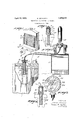
In the-drawings I Figure 1 isaperspectiveview-showing the radiator or con-denser ofa combination cool- 111g system 1 of "thetype-referred to and the connections thereto;
Figure-Qis a sectional; side elevation, partly broken away,-showing the mounting of the temperatureresponsive element and-its con nect'ions: to aninstrument on-ithe radiator Figure?) is a front elevation ofthe-indicahing. instrument;
Figure iris a detail sectional viewsh-owingi a modification of the element mounting; and.
Figure 5 is a sectionalview of. a further modification. 7
Thewinvention. is .shown as applied to a motor vehicle in Which the motor is'made up of-a base block 1 and a cylinder headblolckQ j which are held togetherby cylinder head hold 7 down bolts 8, these: blocks forming thelcyline I de'r chambers land the jacket around the cylinders for the circulation out-the. cooling me- ,dium. The cooling; system employed on this theusua'lewater coolingsystem or under-the if;
steam cooling system, depending on the amount of water in the system.
The cooling system comprises a radiator (condenser) at having a cap 5 which is removable to permit water to be introduced into the system. The radiator differs from the radiator or" the usual water cooled car, in that the pipe 6 for carrying the water and steam from the motor to the radiator is connected to lead into the radiator at one side and at a substantial distance below the top of the radiating portion thereof, the radiator tubes extend horizontally across the radiator, and the pipe 7 for conducting the water from the radiator to the motor is connected to the radiator of the lower end of the side opposite that at which the pipe 6 is connected. /Vith this construction the water or water and steam is caused to circulate horizontally and downward across the radiator with the result that the full width of the radiator is used effectively. It has been found that this system is not only usable for steam cooling, but that it functions more efiectively than the usual radiator when used for water cooling.
When operated as a steam cooling system, there is only enough water in the system to fill the water jackets and the lower part of the radiator (condenser) and the water is pumped from the radiator to maintain the jacket space surrounding the cylinders full of water, by a pump 8 which delivers the water through a pipe 9 to such acket space.
When operated as a water cooled system, the parts and connections are exactly the same, but there is sufficient water in the system to keep the temperature of the cooling liquid below the boiling temperature in the normal operation of the vehicle.
In accordance with the present invention, provision is made for conveniently locating the temperature responsive element of the warning instrument in an environment like that of the cylinder walls themselves and this without the necessity of altering the cylinder castings or departing from standard practice in the construction of the motor in any way. In motors which are provided with a removable cylinder head block, theblock 2 is held down fast to the base portion by cylinder head hold down bolts, some of which extend between the cylinders in contact with the cylinder metal.
In installing the temperature responsive element, one of these bolts is withdrawn and a similar bolt 11, having a central bore 12 therein for receiving a temperature responsive element is substituted in its place. The bore 12 may have a soft plug 10 in its lower end, if desired, which may be removed in part, or altogether to regulate the degree of exposure of the temperature responsive element to the cooling medium. The head of this bolt has an internally threaded opening 13, which is of somewhat larger diameter than the bore 12, so that a shoulder is provided at the junction of the threaded opening 13 and the bore 12. A temperature responsive element 14 having a flange 15 at its upper end is inserted to fit snugly within the bore 12. A nut 16 is threaded into the opening 13 to clamp the element flange down and fix the element securely in place.
WVith the construction described, the ele ment is enabled to derive heat directly from themetal cylinder walls, but is insulated against variable outside influences by the cooling medium which circulates at both sides of the web in proximity to the element. The environment of the element 1 1 is therefore substantially the same as that of the cylinder metal so that the element may be made to accurately reflect the condition of the cylinder metal itself.
This is an extremely desirable condition whether a water or steam cooling system is used, because it may be utilized to give a warning which is more certainly indicative of danger than warning instriunents that are under the sole influence of the cooling medium. Temporary overloading of the motor may result in boiling of the cooling liquid of the Water cooled system, yet may not be indicative of danger at all. Yet, if the operator fails to heed the usual instrument of the prior art whenever it indicates boiling he is running the risk of serious accident on his own responsibility without the aid of any indicating means.
lVith the element mounted as described herein in the water cooled motor, this risk is avoided, for the indication of danger by the instrument is independent or" the boiling of the water, being dependent upon the rise of temperature of the cylinder metal beyond a safe limit, i. e., to a point safely below that at which the pistons will seize.
The temperature responsive element is filled with a suitable heat-expansible liquid and is connected through a braid covered capillary tube 17 with an indicating instrument 18. r
The instrument 18 is shown in the present embodiment as mounted on a radiator cap 5. This location is advantageous because it is conveniently near to the motor, is in direct view of the operator as he watches the road, and accords with the practice to which the public has become accustomed in indicating instruments of this general character. The indicating instrument 18 is of the well known distance type comprising Bourdon and compensating coils, and the necessary operating connections (not shown) for moving a'pointer 19 in response to the variations of temperature at the element 14:. V
:The instrument is provided with a dial plate 20 having a cool zone 21 thereon marked Cool, a danger zone 22 thereon marked Stop and a safe zone between said cooling and danger Zones having a circular opening 23 therein through which light may pass from in front of the instrument to the eye of the operator. The pointer 19 has a c'ir'cu lar enlargement 24 carrying a small "colored celluloid disc 25 therein in position to be moved across the o enings?) in the dial. This indicator may be used either with the steam oiflyvater cooling system;
\Vheh the cooling system is used for'water cooling the pointer will normally occupy a position just to the right of the right hand boundary of the 0001 Zone. Should the coolmg-water be raised to boiling temperature, the pointer "will move across so that the celluloid disc completely covers the opening -23 inthe dial plate.
This shows that the cooling liquid is steaming, but does not indicate a dangerous condition hecause the cylinder metal is still at a safe'tem emaue. It may be due to tern-'- por'ary straining of the motor, in which case the temperature will subside as soon as the straining is relieved. It may be due to the fact that enough water has been lost out of the cooling system to cause operation as steam cooled system. 'Continued operation under-these circumstances will result in no harm.
1 '-Sin.ce the cooling liquid is not lost from this kind of system by evaporation, however, such a'condition is not likely to occurunless there is a leak in the cooling system. The operator may, therefore, continue to operate the'c'ar butis warned that the indication may signify depletion of the cooling liquid, and
he will therefore examine the system at the -first opportunity and replenish the supply of cooling liquid if necessary. If the operator "fails to do this, however, there is absolutely "no danger of damage being done untilthe -cooling liquid falls so'loW that the cooling system cannot adequately control the tern.- perature of the cylinder "metal. Should this occur, the pointer will move over into the danger zone and thereby notify the operfat'or that damage is certain to be done unless the operation *of the vehicle is stopped at once.
Similarly, if the overheating isdue to "otherdangerous'conditions, as failure of lubrication, retarded spark, or stuck valves, the pointer will move over into the danger zone shortly before the temperature of the -''-cylinder metal is reached which would be dangerous, and this even though the cooling "system be completely 'filled with cooling liquid. v
VVhenthe cooling system is filled only with enough liquid to operate as a steam'cooling system, the pointer 19 will normally occupy position such that the celluloid disc will cover the opening 23 in'the dial,but "the oc- "cu'r're'nce of adangerous condition causing the pointer to move over into the danger zone.- I
It will thus be seen that thepresent invention provides for use in combination with either'a water cooled or team cooled motor, or with a motor having a cooling system operable under eithersystem, an'instrument which is applicable to either system and which will give a definite and positive indication of danger without needlessly or prematurely alarming the operator when boiling occurs unaccompanied by a'condition which is truly indicative of danger.
Another important advantage of mounting the temperature responsive element in the location described is that a warning signal'is quickly given on-starting the motor, even if the cooling liquid has all. leaked away during theper-iod of disuse. Where the temperature of the cooling medium is relied on for giving a warning, a complete or substantial absen'ce'of cooling liquid will prevent the Warningsignal from functioning. With the mounting as described; how- 'ever,'t he temperature of the element is quickly'raised to the danger point to cause a wran'ing to be given, even though no cooling liquid'is present. p
In the form ofthe invei'ition'disclosed in Figure l the temperature responsive element is mounted outside the motor casting butin position to derive heat'directly from the cylinder metalandto be controlled in part bythe cooling medium. This form of the invention is designed especially for applicationito a motor in 'which'the cylinder head is held down by nuts screwed ont'othe'u-pjper end of the hold down bolts, and may be very easily applied by the car owner o'r' a dealer, the'element mounting being substitutedfo'r the hold down nut. A cylinder head hold down nut is removed from its bolt '26. A nut 27', having an upstanding stem 28 projecting therefrom, is threaded onto the upper end ofjthe bolt 26 to bear upon the cylinder head block so that the "combined bolt and'nut' serve'the function of the usualhold down bolt and nut. The stem 28 is provided with a well in its upper end in which the v temperature responsive element 29 is mounted. A nutf30 threaded into the upper end ofthe stem 28 'to' holdthe temperature responsive element in place, the element mounting being the same as that disclosed in Figure2.' A heat "insulating sleeve 31 of 'h'ardrubber orothe'r suitable material, surrounds'the' stem '28 to insulate the temperature responsive element from the influence of the atmospher'ietemperature;
The "bolt-'26 is in the same environment ence of the cooling; medium. The temperature'o'f the element 29 is therefore dependent overlooked by the operator.
,perature of the motor.
upon both these factors, although its temperature will lag behind that of the bolt 26.
The. element is connected through a capillary tube 32 to operate a warning instrument like that disclosed in Figure 3, the only difference being that the instrument is calibrated to take into account the fact that the element is at a lower temperature than the pin 26 so that the desired indications will be given under the proper conditions of motor operation.
In the form of the invention shown in Figure 5 the usual hold down bolt is replaced by a bolt 32 having a nut portion 33 for holding the cylinder head block down and anupstanding stem 34 provided with a well for the reception of a temperature responsive element 35. This element is held in place by a nut 36, as in the other forms of the invention described. A heat insulating sleeve 37 surrounds the stem 34.
The instrument installation described is of special value, also, when combined with a motor having a cooling system of the thermosyphon type. lVith this type of cooling the normal motor operating temperature is very little below the boiling point, so that the warning indicator under the influence of the cooling medium moves only a very short distance from its position in the normal operation of the motor to a position which it takes up when boiling occurs in the system. The movement of the indicator is so small, therefore, that it is apt to be By mounting the temperature responsive element in the cylinder metal the movement of the indicator hand is not limited by a position corresponding to the boiling temperature, but moves through a very considerable distance to a position corresponding to the overheated tem- It is thus capable of giving a significant and conspicuous warning when danger occurs.
It will be seen that the present instrument, whether applied to the steam cooled or water cooled system, is more keenly an alytical of motor operating conditions than the instruments of the prior art which have depended solely on the temperature or other characteristics of the cooling medium for their control and that its indications are therefore more informative than the indications of such previous instruments.
It will be seen further that provision is made for mounting the temperature responsive element in the desired environment without any necessity for alteration in the motor on the part of the manufacturers, and that the parts employed in achieving this result are inexpensive and can be easily and quickly applied by anyone.
Variations may be resorted to within the scope of the invention and parts of the improvements may be used without others.
What I claim is:
1. In combination, motor cooling means operable either as a water or constant temperature cooling system, and a heat-responsive instrument constructed and arranged to warn of dangerous operating conditions under either cooling system, comprising an indictor and an indicator controlling element mounted to be subject to direct heating by the cylinder metal and to the indirect action of the cooling medium through the cylinder metal.
2. In combination, an internal combustion engine having a Water cooling system, a heatresponsive means embedded Within the metal of the cylinders adjacent to the cooling space, an indicator and means whereby the indicator is controlled by the heat-responsive means. 1
3. In a motor vehicle, a motor comprising a cylinder head block, means for holding down the cylinder head block comprising a bolt penetrating a cylinder Wall and having a socket therein, a temperature responsive element mounted in the socket in said bolt to be controlled by the temperature of the cylinder metal and means operated by said element to give a warning indication.
i. In a motor vehicle, a motor casting, a member extending into thev casting and imbedded in a cylinder wall to derive heat directly therefrom independently of the cooling medium and to have its temperature controlled in part from the cooling medium, a temperature responsive elementmounted in thermally conductive relation with said member to derive heat from it, indicating means and means whereby the indicating means is operated from said element.
5. In a motor vehicle, a motor casting, a
member extending into the casting and penetrating a cylinder wall to derive heat directly therefrom, and to have its temperature controlled in part from the cooling medium, said member having a socket therein, a temperature responsive element in the socket in said member, indicating means and means whereby the indicating means is operated from said element. 7
6. In combination, a member substitutable in a motor for a standard part that extends into. the motor casting and penetrates a cylinder wall in proximity to the circulating space of the cooling medium and performing the function of such standard part, a temperature responsive element carried by said member to derive heat from it, indicating means and means whereby the indicating means is operated from said element.
7 In a motor vehicle, the combination with a motor comprising a member extending in proximity to a cylinder wall and in direct heat transferring relation therewith and also in proximity to the circulating space of the cooling medium, of a temperature responsive element mounted on said member, indicating means and means whereby the indicating means is operated from said element, and heat insulating means guarding the temperature responsive element against external influences.
8. In combination, a motor, a bolt extending into the motor and penetrating a cylinder Wall thereof, said bolt having a portion projecting beyond the motor and having a socket therein, and a Warning instrument comprising a temperature responsive element mounted in the socket in the projecting portion of the bolt.
In'testimony whereof I have aflixed my signature to this specification.
HERMAN SCHLAICI-I.
Priority Applications (1)
| Application Number | Priority Date | Filing Date | Title |
|---|---|---|---|
| US93082A US1854072A (en) | 1926-03-08 | 1926-03-08 | Indicating and warning instrument |
Applications Claiming Priority (1)
| Application Number | Priority Date | Filing Date | Title |
|---|---|---|---|
| US93082A US1854072A (en) | 1926-03-08 | 1926-03-08 | Indicating and warning instrument |
Publications (1)
| Publication Number | Publication Date |
|---|---|
| US1854072A true US1854072A (en) | 1932-04-12 |
Family
ID=22236913
Family Applications (1)
| Application Number | Title | Priority Date | Filing Date |
|---|---|---|---|
| US93082A Expired - Lifetime US1854072A (en) | 1926-03-08 | 1926-03-08 | Indicating and warning instrument |
Country Status (1)
| Country | Link |
|---|---|
| US (1) | US1854072A (en) |
Cited By (3)
| Publication number | Priority date | Publication date | Assignee | Title |
|---|---|---|---|---|
| US2460748A (en) * | 1944-09-14 | 1949-02-01 | United Aircraft Corp | Automatic temperature control apparatus |
| US2641239A (en) * | 1951-06-14 | 1953-06-09 | Phillips Mfg Company Inc | Electrical head bolt replacement heater for liquid cooled internal-combustion engines |
| US3221125A (en) * | 1963-02-14 | 1965-11-30 | Gen Motors Corp | Temperature switch having slidable thermal exchanger |
-
1926
- 1926-03-08 US US93082A patent/US1854072A/en not_active Expired - Lifetime
Cited By (3)
| Publication number | Priority date | Publication date | Assignee | Title |
|---|---|---|---|---|
| US2460748A (en) * | 1944-09-14 | 1949-02-01 | United Aircraft Corp | Automatic temperature control apparatus |
| US2641239A (en) * | 1951-06-14 | 1953-06-09 | Phillips Mfg Company Inc | Electrical head bolt replacement heater for liquid cooled internal-combustion engines |
| US3221125A (en) * | 1963-02-14 | 1965-11-30 | Gen Motors Corp | Temperature switch having slidable thermal exchanger |
Similar Documents
| Publication | Publication Date | Title |
|---|---|---|
| US1820035A (en) | Temperature regulator | |
| US1854072A (en) | Indicating and warning instrument | |
| US3703693A (en) | Liquid level sensing system | |
| US3302171A (en) | Vehicle engine coolant condition indicator | |
| US1090776A (en) | Indicating system and apparatus for internal-combustion engines. | |
| US2037748A (en) | Indicating device for engine cooling systems | |
| US2532182A (en) | Safety switch for engine cooling systems | |
| US1206783A (en) | Temperature-indicating system and apparatus for internal-combustion engines. | |
| KR19990009699A (en) | Cooling water temperature prediction method in case of vehicle cooling water temperature sensor failure | |
| US1879428A (en) | Temperature indicator | |
| US1916237A (en) | Heater | |
| US1773756A (en) | Indicating device | |
| US1745063A (en) | Means for introducing temperature-responsive elements into enginecooling systems | |
| US1444133A (en) | Thermometer attachment for automobiles | |
| US2046140A (en) | Brake mechanism | |
| US1580151A (en) | Radiator cap and indicator | |
| US1696393A (en) | Motor gauge | |
| US1591137A (en) | Pressure indicator | |
| US1161530A (en) | Temperature-indicator. | |
| US1220150A (en) | Thermometer for the cooling systems of internal-combustion engines. | |
| US1834797A (en) | Overflow and steam indicator for automobiles | |
| US1493938A (en) | Antifreeze condenser | |
| US1713107A (en) | Indicator for water-cooled engines | |
| US2211394A (en) | Device for indicating freezing temperature of liquids | |
| US1680425A (en) | louis |