US185406A - Improvement in machines for making lead pipes - Google Patents
Improvement in machines for making lead pipes Download PDFInfo
- Publication number
- US185406A US185406A US185406DA US185406A US 185406 A US185406 A US 185406A US 185406D A US185406D A US 185406DA US 185406 A US185406 A US 185406A
- Authority
- US
- United States
- Prior art keywords
- lead
- cylinder
- pipe
- machines
- improvement
- Prior art date
- Legal status (The legal status is an assumption and is not a legal conclusion. Google has not performed a legal analysis and makes no representation as to the accuracy of the status listed.)
- Expired - Lifetime
Links
Images
Classifications
-
- B—PERFORMING OPERATIONS; TRANSPORTING
- B21—MECHANICAL METAL-WORKING WITHOUT ESSENTIALLY REMOVING MATERIAL; PUNCHING METAL
- B21C—MANUFACTURE OF METAL SHEETS, WIRE, RODS, TUBES, PROFILES OR LIKE SEMI-MANUFACTURED PRODUCTS OTHERWISE THAN BY ROLLING; AUXILIARY OPERATIONS USED IN CONNECTION WITH METAL-WORKING WITHOUT ESSENTIALLY REMOVING MATERIAL
- B21C27/00—Containers for metal to be extruded
Definitions
- This invention relates to lead-pipe presses in which the lead is cast before it is pressed out in the form of pipe.
- the invention consists in forming the leadcylinder (cylinder containing the lead) with a chamber or passage in the solid metal of the sides of the cylin der from top to bottom near-- ly, having preferably an outlet near the top, and an outlet near the bottom, in combination with the other-devices set forth and claimed.
- the coil passage or chamber is for the purpose of heating the cylinder by steam when commencing to make pipe. heretofore been done by putting the cylinder in an oven, or by other slow and difficult Ways,
- the running of the hot lead into the cylinder iucreases the heat until it becomes so hot that much time is lost in waiting for the lead to cool to the proper temperature for working. This loss of time is obviated by running water through the coiled passage to cool the cyt inder.
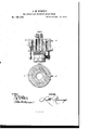
- Figure 1 is an axial section of the lead-cylinder at x x, Fig. 2.
- Fig. 2 is a section of the cylinder at x' x', Fg. 1.
- A is the head of the hydrostatic ram, upon which the lead-cylinder is supported, and by which it is raised. It is not necessary to give any particular description either of the ram A or of the hollow piston B, through which the lead pipe is forced through a triblet, b, as these parts are well known, and no novelty is claimed in them.
- the cylinder O is firmly secured upon the ram Ain an axial position
- Such heating has and is raised and lowered with the ram, in the usuai manner.
- the cylinder is first heated to receive the molten lead, and then cooled to reduce the lead to the proper temperaturc for the production of the pipe.
- I also have a tubular core, l), Fig. 1, the perforation connecting with an opening or perforation in or under the core box. which allows water to pass down through the core, and out through or under the core-box;
- a piece of ordinury hose or tubing is used, said hose or tubing having at its end aconical piece of hollow metal to suit any sized pipe, and to prevent the hot lead pipe from bnrnng the hose or tube which conveys the air or water.
- the lead pipe is forced out, by the usual means, over the hollow core, and the end is cut oft ⁇ V at the top of the machine.
- the conical cup or tube' attached to the hose is placed on the end of the lead pipe, and water is turned on or air forced in, which runs through the end of the lead pipe, down through the hollow core, and out'through the core-box.
- the Operation is continued as long as the molten lead remains at the proper temperature, and as soon as the lead in the cylinder is chilled the conical cup is detached LEWIS M. RUMSEY.
Landscapes
- Engineering & Computer Science (AREA)
- Mechanical Engineering (AREA)
- Continuous Casting (AREA)
Description
S'r'rs" LEWIS M. RUMSEY, OF ST. LOUIS, MISSOURI, ASSIGNOR OF ONE-HALF HIS RIGHT TO MOSES .RUil/ISEY, OF SAME PLAOE.
IMPRvi-:MENT IN MAcHINEs FOR MAKING LEAD PIPES.
Specfication forming part of Letters PatentNo, iflbfi, dated' December 19, 1876; application tiled May 13, 1e76.
To all whom it may concem:
Be it known that I, LEWIs M. RUMSEY, of
the city and county of St. Louis, and State of Missouri, have invented a certain new and useful Improvement in Presses used in the Manufacture of Lead Pipe; and I do hereby declare the following to be a full, clear, and exact description of the same, reference being had to the accompanying drawings, making part of this specification.
This invention relates to lead-pipe presses in which the lead is cast before it is pressed out in the form of pipe.
The invention consists in forming the leadcylinder (cylinder containing the lead) with a chamber or passage in the solid metal of the sides of the cylin der from top to bottom near-- ly, having preferably an outlet near the top, and an outlet near the bottom, in combination with the other-devices set forth and claimed.
The coil passage or chamber is for the purpose of heating the cylinder by steam when commencing to make pipe. heretofore been done by putting the cylinder in an oven, or by other slow and difficult Ways, The running of the hot lead into the cylinder iucreases the heat until it becomes so hot that much time is lost in waiting for the lead to cool to the proper temperature for working. This loss of time is obviated by running water through the coiled passage to cool the cyt inder. By the use of this coil in the sides of the cylinder for heating it by steam and cooling it by water, two coils of lead pipe can be made in the time required to make one coil by the old process, and the time saved and trouble avoided ot' removal, heating, and re placing the cylinder.
Figure 1 is an axial section of the lead-cylinder at x x, Fig. 2. Fig. 2 is a section of the cylinder at x' x', Fg. 1.
A is the head of the hydrostatic ram, upon which the lead-cylinder is supported, and by which it is raised. It is not necessary to give any particular description either of the ram A or of the hollow piston B, through which the lead pipe is forced through a triblet, b, as these parts are well known, and no novelty is claimed in them. The cylinder O is firmly secured upon the ram Ain an axial position,
Such heating has and is raised and lowered with the ram, in the usuai manner.
In my preferred manner of constructing the cylinder O, I place the coiled pipe c in the mold, and cast the cylinder upon it, the pipe or coil forming a spiral passage through the body of metal forming the sides of the cylinder. The ends 01 02 of the coil c are shown as projecting from the cylinder near the bottom and top, and these ends are to be connected by flexible couplings to steam and water pipes, so that either steam or water may be passed through the coil c, as desired, to either heat or cool the cylinder.
vThe cylinder is first heated to receive the molten lead, and then cooled to reduce the lead to the proper temperaturc for the production of the pipe.
I have described a coil, c, running -spirally through the sides of the cylinder, but it is evident that an annular chamber in the same position as the coil c would answer substantially the same purpose, although, perhaps, in a less satisfaetory manner, and would be a mere modifieation of my invention.
Any convenient lieating and cooling fluid may be used in place of the steam and water described.
I also have a tubular core, l), Fig. 1, the perforation connecting with an opening or perforation in or under the core box. which allows water to pass down through the core, and out through or under the core-box;
Then the hot lead is'run into the cylinder,
water is immediately turned into the hollow portion in the core, which chills and hardens the lead in contact with the core, making it possible to start the press much quicker than it could otherwise be started, whereby much valuable time is saved.
It is evident that any Opening through or below the core-box, in connection with the opening in the core, would answer the same purpose, so long as it allowed the escape of the water.
In running water or forcing air through the hollow core and corebox, a piece of ordinury hose or tubing is used, said hose or tubing having at its end aconical piece of hollow metal to suit any sized pipe, and to prevent the hot lead pipe from bnrnng the hose or tube which conveys the air or water.
In the process of manufacture, the lead pipe is forced out, by the usual means, over the hollow core, and the end is cut oft`V at the top of the machine. As soon as it is cut o` the conical cup or tube' attached to the hose is placed on the end of the lead pipe, and water is turned on or air forced in, which runs through the end of the lead pipe, down through the hollow core, and out'through the core-box. The Operation is continued as long as the molten lead remains at the proper temperature, and as soon as the lead in the cylinder is chilled the conical cup is detached LEWIS M. RUMSEY.
Witnesses:
SAML. KNIGHT. Mosns RUMSEY.
Publications (1)
| Publication Number | Publication Date |
|---|---|
| US185406A true US185406A (en) | 1876-12-19 |
Family
ID=2254812
Family Applications (1)
| Application Number | Title | Priority Date | Filing Date |
|---|---|---|---|
| US185406D Expired - Lifetime US185406A (en) | Improvement in machines for making lead pipes |
Country Status (1)
| Country | Link |
|---|---|
| US (1) | US185406A (en) |
-
0
- US US185406D patent/US185406A/en not_active Expired - Lifetime
Similar Documents
| Publication | Publication Date | Title |
|---|---|---|
| US1847573A (en) | Platen for presses with heating coils | |
| US185406A (en) | Improvement in machines for making lead pipes | |
| US648091A (en) | Apparatus for casting ingots in continuous long lenghts. | |
| US443536A (en) | Art and means for covering and insulating wire | |
| US265156A (en) | Tuyere | |
| US1469747A (en) | Hot die for plastic molding | |
| US1472047A (en) | Method of lapping metal pipes | |
| US185376A (en) | Improvement in processes for casting metals | |
| US1219358A (en) | Method of molten-metal feed for die-casting. | |
| US1466125A (en) | Oiler for metal-casting machines | |
| US408374A (en) | Method of incasing tubing composed of plastic materials | |
| US760220A (en) | Machine for upsetting metal. | |
| US220767A (en) | Improvement in soft-metal traps | |
| US2249775A (en) | Method of producing tubular metallic bodies | |
| US476799A (en) | Process of and machine for making emery-wheels | |
| US7624A (en) | Manufacture of lead pipe | |
| US3475A (en) | Machinery eoe the manufacture of lead pipes | |
| US827223A (en) | Core. | |
| US148870A (en) | Improvement in apparatus for pressing meat scraps | |
| US797022A (en) | Means for cooling stereotype-casting boxes. | |
| US8051A (en) | james reynolds | |
| US131486A (en) | Improvement in the modes of casting wheels and pinions | |
| US907077A (en) | Apparatus for manufacturing lead traps by hydraulic pressure. | |
| US1111198A (en) | Apparatus for shaping metal articles. | |
| DE415802C (en) | Pouring funnel |