US1854067A - Hydraulic brake - Google Patents
Hydraulic brake Download PDFInfo
- Publication number
- US1854067A US1854067A US371835A US37183529A US1854067A US 1854067 A US1854067 A US 1854067A US 371835 A US371835 A US 371835A US 37183529 A US37183529 A US 37183529A US 1854067 A US1854067 A US 1854067A
- Authority
- US
- United States
- Prior art keywords
- cam
- pistons
- intake
- cylinders
- cylinder block
- Prior art date
- Legal status (The legal status is an assumption and is not a legal conclusion. Google has not performed a legal analysis and makes no representation as to the accuracy of the status listed.)
- Expired - Lifetime
Links
- 239000007788 liquid Substances 0.000 description 36
- 239000012530 fluid Substances 0.000 description 32
- 239000004020 conductor Substances 0.000 description 29
- 230000033001 locomotion Effects 0.000 description 28
- 230000004087 circulation Effects 0.000 description 20
- 230000006835 compression Effects 0.000 description 15
- 238000007906 compression Methods 0.000 description 15
- 230000000979 retarding effect Effects 0.000 description 12
- 210000005069 ears Anatomy 0.000 description 5
- 238000005553 drilling Methods 0.000 description 4
- 238000010276 construction Methods 0.000 description 3
- 230000014759 maintenance of location Effects 0.000 description 3
- 210000002445 nipple Anatomy 0.000 description 2
- 238000012856 packing Methods 0.000 description 2
- 230000002093 peripheral effect Effects 0.000 description 2
- 150000001450 anions Chemical class 0.000 description 1
- 230000015572 biosynthetic process Effects 0.000 description 1
- 238000001816 cooling Methods 0.000 description 1
- VKYKSIONXSXAKP-UHFFFAOYSA-N hexamethylenetetramine Chemical compound C1N(C2)CN3CN1CN2C3 VKYKSIONXSXAKP-UHFFFAOYSA-N 0.000 description 1
- 238000003780 insertion Methods 0.000 description 1
- 230000037431 insertion Effects 0.000 description 1
- 238000009434 installation Methods 0.000 description 1
- 239000000314 lubricant Substances 0.000 description 1
- 238000005461 lubrication Methods 0.000 description 1
- 238000004519 manufacturing process Methods 0.000 description 1
- 229910000498 pewter Inorganic materials 0.000 description 1
- 239000010957 pewter Substances 0.000 description 1
- 108010085990 projectin Proteins 0.000 description 1
- 230000003014 reinforcing effect Effects 0.000 description 1
- 230000000717 retained effect Effects 0.000 description 1
- 238000005096 rolling process Methods 0.000 description 1
Images

Classifications
-
- F—MECHANICAL ENGINEERING; LIGHTING; HEATING; WEAPONS; BLASTING
- F16—ENGINEERING ELEMENTS AND UNITS; GENERAL MEASURES FOR PRODUCING AND MAINTAINING EFFECTIVE FUNCTIONING OF MACHINES OR INSTALLATIONS; THERMAL INSULATION IN GENERAL
- F16D—COUPLINGS FOR TRANSMITTING ROTATION; CLUTCHES; BRAKES
- F16D57/00—Liquid-resistance brakes; Brakes using the internal friction of fluids or fluid-like media, e.g. powders
- F16D57/06—Liquid-resistance brakes; Brakes using the internal friction of fluids or fluid-like media, e.g. powders comprising a pump circulating fluid, braking being effected by throttling of the circulation
Definitions
- the present invention relates to improvements 1n brake mechanism primarily 1n tended for use 1n connectlon w1th automotlve vehicles, and the primary object of the in-' vention is to provide an improved fluid operated brake embodying novel operating features whereby the vehicle wheels may be gradually retarded against rotation to various degrees or locked against rotation by the action of a fluid under compression.v
- a further object of the invention is to provide a fluid operated brake wherein the rotary movement of the wheels acts to compress the body of fluid which in turn acts to retard rotation of the wheel in accordance with the opening and closing of a manually operated control valve.
- a further object of the invention is to provide an improved hydraulic brake embodying a series offluid compressing cylinders and actuating means therefor automatically operable upon rotation of the wheel in a manner whereby upon operation, the cylinders operate successively for creating a gradual braking action on the wheels.
- a further object of the invention is to provide a hydraulic brake mechanism for vehicle wheels wherein the fluid is not retained under compression during normal running of the vehicle, and one whereinthe. degreeof braking action is controlled by a valve serving to bypass more or less of the fluid when com pressed by rotary action of the wheel.
- a still further object of the invention is to provide a brake mechanism for vehicle wheels embodying a stationary cylinder block having novel features of construction whereby the block serves as a mounting for the compression cylinders and various check valves serving to control the flow of fluid serving as a medium for creating the braking action.
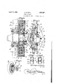
- Figure 1 is a View of the inner edge of the rotary drum and showing the stationary cylproviding a housing for the cylinder block.
- inder block in section for illustrating the particular arrangement of com ressors and the various channels or ducts or the fluid medium.
- Figure 2 is a diagrammatic top plan View of the rear portion of a motor vehicle and showing the improved brake mechanism as applied thereto.
- Figure 3 is a diagrammatic view showing the particular arrangement of the cam surfaces of the rotary drum.
- Figure 4 is a section on line 4-4 of Figure 1 and showing the manner in which the mechanism is associated with the conventional type of vehicle wheel.
- Figure 5 is a view part in side elevation and part in section of-the stationary cylin-. der block and showing the. manner in which the same may be drilled for' providing the fluid passageways.
- Figure 6 is a detail perspective view showing the manner in which the brake drum is applied to the inner side of the vehicle wheel and the "cover plate for the brake drum for 78
- Figure 7 is a fragmentary detail perspective view of one of the intake check valves.
- Figure 8 is a fragmentary section thru one of the exhaust check valves.
- the letter A designates a conventional type of motor vehicle chassis embodying a pair of rear wheels B mounted upon an axle C enclosed within-the usual fixed axle'hous- 'ing D.
- a cam drum E mounted for rotation with the wheels B is a cam drum E in which is mounted a stationary cylinder block F provided with fluid compressor means G operable for creating a braking action upon the wheels B as by the control means H.
- the axle housing D for enclosing the axle C is stationary as in usual practice,.and is provided at its end with an annular flan e 10 of a diameter less than that of the cam rum E.
- This flange 10 serves as means for rigid mounting of the cylinder blockF against rotation within the cam drum E.
- a cam mm 13 Arranged at the peripheral portion of the plate 11 and pro- ]ecting inwardly from the wheel is a cam mm 13 provided at its outer side with c rcumferentially extending ribs or fins 14 which act as reinforcing means forthe rim and also act in the capacity of cooling fins for the rim.
- the internal surface of the rim 13 is'provided with a series of equi-distantly spaced apart cam projections 15 which in the example shown are five in number and are arranged at 72 apart.
- each of the cam projections 15 is arranged at a point diametrically-o posite to the low side of the cam surface ormed at the inner side of'the rim 13.
- a cover plate 16 which is secured at its peripheral portion to the inner edge of the rim 13 as by means of a suitable number of cap bolts 17 threaded into the openings 18 in the rim.
- This cover plate 16 is rovided with an axial opening of greater than that of the axle housing D but of less diameter than that of the flange 10 so that the cover plate overlies the inner side of the flange 10 in a manner as illustrated in Figure 4.
- An annular packing ring 19 isarranged between the overlapping portions of the flange 10 and plate 16, and thus it will be seen that a closed housing is provided for mounting of the stationary cylinder block F and its associated parts.
- the housing1 thus formed provides an oil reservoir in w ich a suitable quantity of lubricant may be maintained for lubrication of the fluid compressor means Gr.
- the same is of a one-piece construction and embodies an annular or ring-shaped body portion 20 forming an axial opening 21 thru which the rotating axle C may pass.
- each of the intake chambers 24 and extending to the inner side of the annular body 20 Opening into the inner end of each of the intake chambers 24 and extending to the inner side of the annular body 20 is a threaded inlet opening 26, while opening into the inner end of each of the outlet chambers 25 and extending to the inner side of the radially of the iameter annular body 20 is a threaded outlet opening 27.
- the chambers 24 and 25 open to the inner side of the annular body portion 20 thru the openings 26 and 27 respectively.
- cylinder formin bores 28 which also extend ody 2Q and are preferably of slightly greater diameter than that of the radially extending bores 22.
- Drilled or otherwise formed in the ring-shaped body 20 and'opening at the circumferential face thereof between each of the adjacent bores 22 and 28 is a series of tangentially arranged bores forming intake and exhaust'channels 30 and 31 respectively being closed at their outer end as by means of suitable plugs 32.
- These channel forming bores 30 and 31 intersect at each of the bores 22 and have their inner ends opening into the cylinder forming bores 28 as'clearly illustrated in Figures 1 and 5.
- the channels 30 and 31 form a polygonal-shaped passageway forming communication between the inner end of each of the cylinder forming bores 28 and the chambers 24 and 25 whereby a suitable fluid, preferably in the nature of oil, may have ready communication between the intake and outlet chambers and their respective cylinder forming bores.
- a suitable fluid preferably in the nature of oil
- the cylinder block F is rendered susceptible of ready manufacture for formation of the communicating channels between the intake and outlet chambers 24 and 25 respectively and their respective cylinder forming bores.
- This drilling of the channels 30 and 31 also renders possible the installation of suitable check valves to be subsequently described.
- the cylinder block F is intended to have its inner face arranged in abutting relation with the outer face of the axle housing flange 10 and is secured to the flange as by means of suitable bolts 34 passing thru suitable apertures 35 extending transversely thru the ring-shaped body 20 between the openings 26 and 27 and inwardly of the polygonal-shaped passageway formed by the channels 30 and 31.
- suitable bolts 34 passing thru suitable apertures 35 extending transversely thru the ring-shaped body 20 between the openings 26 and 27 and inwardly of the polygonal-shaped passageway formed by the channels 30 and 31.
- a check valve structure 40 Mounted within each of the intake channels 30 between the intake chamber 24 and each of its companion cylinder forming bores 28, is a check valve structure 40 embodying a tubular sleeve portion 41 provided at its exit end with hook-shaped arms 42 serving as a retention means for a ball valve 43 adapted to engage upon the seat 44 in a manner whereby the intake check valve structures 40 serve for allowing passage of the oil from the chambers 24 to each of the companion cylinders 28 and prevents retrograde movement of the oil to the chambers 24 upon seating of the ball valves 43.
- an exhaust check valve structure 45 is arranged within each of the exhaust channels 31 between the intake chambers 24 and their companion cylinders 28, a exhaust check valve structure 45 in the form of a tubular sleeve 46 having a valve seat forming opening 47 provide at its intake end for seatmg engagement of a ball valve 48 held in position within the sleeve as by means of fingers 49 struck inwardly of the sleeve in slightly spaced relation from the intake end thereof.
- These exhaust check valve structures 45 act to allow free passage of oil to the exhaust chambers but prevent retrograde movement of the oil from the chambers to their respective cylinders upon seating of the ball valve 48.
- a set of spaced apertured ears 49 Projecting radially from the circumference of the ring-shaped body portion 20 at each of the radially extending bores 22, a set of spaced apertured ears 49 which preferably extend from the inner and outer faces of the annular ring-shaped body. These ears arms 0 49 serve as a mounting for pivoted members of the fluid compressor means G and are ref erably cast integralwith the annular ody 20. As will be observed, there are four of these sets of ears 49, one for each of the cylinders 28.
- the fluid compressor means G which acts upon rotary movement of the cam drum E for compressing of the fluid and acting to retard rotation of the vehicle wheel
- the same embodies a series of similarly formed anchor arms or levers 50, 51, 52 and 53 each of which are pivotally connected as by means of a suitable hinge pin 54 between each of the sets of ears 49 and extend therefrom in a like general direction circumferentially of the annular body 20 in tangential relation thereto in the annular race way 55 formed between the periphery of the annular body 20 and inner cam surface of the cam rim 13.
- each of the anchor arms 50, 51, 52 and 53 is provided with a bifurcated head 56 which is disposed in overlying relation at the outer end of each of the c linders 28, and mounted between the f the bifurcated head 56 as upon suitable pins 57, are suitable rollers-58 for rolling contact with the inner peri hery of the cam' rim 13.
- the inner side 0 each of the heads 56 is provided with a convex bearing surface 59 which is intended to bear u on a convex-shaped head of cup-shaped pistons 60 slidably mounted in the cylinders 28 which pistons act as a closure means for the cylinders.
- each of the cup-shaped pistons 60 Disposed inwardly of each of the cup-shaped pistons 60 is an expansion coil spring 61 one end of which acts upon the iston and t e opposite end a ainst the wal at the inner end of the cylin er forming bores 28 in a manner for normally urging the pistons outwardly into contact with the anchor arm heads 56.
- one of the radially movin pistons 60 is provided for each of the anc or arms 50 51, 52 and'53, and that each piston is operated independently of the com anion pistons. It will also be observed t at during rotary movement of the cam drum E, that the free ends of the anchor arms will be moved inwardly and outwardly radially of the stationary cylinder block F for reciprocatory movement of the pistons 60.
- spiral expander springs 64 the outer ends of which act upon the intermediate portion of the anchorarms for normally urging the head portions 56 of the arms into intimate contact with the inner periphery of the cam rim 13.
- a fluid supply tank 65 which may be mounted at any suitable air vent 66.
- an intake pipe or conductor 67 which is provided at opposite ends with -Y fittings 68 from which branch conductors 69 lead and are coupled as by means of suitable nipples 70, one into each of the threaded inlet openings 26 communicating with the intake chambers 24.
- an exhaust pipe or conductor 71 provided at opposite ends with Y fittings 72 having branch conductors 73 leading thererom and connected as by.
- nipples 74 one into each of the threaded outlet openings 27 communicating with the outletor exhaust chambers 25.
- a control valve 75 operable for opening and closing communication thru the exhaust conductor upon actuation of a suitable lever or pedal 76 operatively connected as bysuitable links and levers with an operating arm ward swinging of the pedal for partially or 1 wheels B in either direction will projections has been wholly shutting ofi communication of the fluid thru the exhaust conductor 71 into'the tank 65 in accordance with the degree of braking action desired to be obtained upon the vehicle wheels B.
- the control valve 75 When the control valve 75 is in its full open position, rotation of the cause the fluid to have free circulation between the tank 65 and cylinder block F thru the conductors 67 and 71 in indicated in Figure 2.
- Fi ures 1 and 3 wherein it wi be observed t at the pistons 60 are four in number and arranged at 90 apart, and that the cam projections 5 are five in number and are arranged 72 apart, it will be seen that there are an even number of istons' while the number of cam projections 1s of an uneven number and greater than that of the number of pistons.
- valve 75 has been only partially closed such will allow for slow passage of the fluid thru the valve and thus create a gradual braking action in accordance with the amount of fluid allowed to bypass thru the valve. It may be further stated that by so having the cam projections 15 alternately engage the rollers of the anchor arms that one of the anchor arms will at all times be acting to retard rotation of the cam drum and thus not create an intermittent or jerking action.
- the valve 75 is fully closed such as when making an emergency or quick stop, the fluid is quickly compressed in the discharge conductor 71 and thus locks the wheels against rotation by preventing a of the anchor arms.
- bra as being applied to vehicle wheels for retarding rotation thereof, it. will be readily apparent that the device may equally well be employed for use in creating a braking action upon rotary members of various descriptions.
- a hydraulic brake comprising a 'stationary cylinder block provided with a series of radially arranged cylinders opening at the circumference of the block, a body of liquid having communication thru the block with tial face of the cyllnder block means normally urging said pistons outwardly of the cylinders, a rotatable cam drum mounted concentric to the cylinder block and having a series of cam projections formed at its inner periphery, braking elements pivotally carried by the stationary cylinder block and engaggig one with each of said pistons, said ra 'ng elements engaging the cam pro ections for moving their respective pistons inwardly and causin a forced circulation of said liquid in one irection, means normally urging the braking elements into engagement with said cam drum, and means for variably restricting circulation of the liquid for retarding compression movement of said pistons by the braking elements.
- a hydraulic brake comprising a stationary cylinder block provided with a series of radially arranged cylinders, a body of liquid having communication thru the block with each cylinder, a piston in each cylinder and projectin radially from the cylinder block, a rotata 1e cam drum mounted concentric tothe cylinder block and having a series of cam projections formed at its inner periphery, an anchor arm pivotally carried by the cylinder block for each cylinder andhaving its free end slidably engaging its respective piston and engaged by the cam projections for inward movement of the pistons and causing a forced circulation of said liquid in one directlon, means normally urging the pistons outwardly and the anchor arms into engagement with the cam drum, and means for variably restricting circulation of the liquid for retarding inward movement of the pistons by their respective anchor arms.
- a hydraulic brake comprising a stationary cylinder block provided with a series of radially opening cylinders, a body of liquid having communication thru the block with the cylinders, a piston movable in each cylinder and projecting from the cylinder block, spring means normally urging each piston outwardly, a rotatable drum embodying a cam rim arranged concentric to the cylinder block, anchor arms each pivotally mounted at one end upon the cylinder block between each cylinder and each having its free end' engaging one with each of the pistons, 'a
- each anchor arm carried by the free end of each anchor arm and engaging the cam rim for moving said pistons lnwardly and causing a forced circulation of said liquid in one direction
- a hydraulic brake comprising a stationary annular cylinder block provided with a series of equi-distantly spaced apart radially o ning'cylinders, a body of li uid havin co dimunication thru the block gvith the cy inders, a piston movable in each cylinder, a rotatable drum embodying a cam rim mounted concentric to the cylinder block and provided at its inner periphery with a series of equi-distantly spaced apart inward ly projecting cam projections spaced less degrees apart about the circumference of the rim than the spacing ofsaid cylinders, braking elements carried by the stationary cylinder block for each piston and alternately engageable by the .cam projections for moving said pistons inwardly and causing a forced circulationof said liquid in one direction,
- a hydraulic brake comprising a stationary annular cylinder block provided with a series of radially opening cylinders, and a series of connected channels forming communication between the cylinders, a body of liquid having communication with the cylinders thru said channels, connectedintake and exhaust conductors connecting certain of said channels, check valves mounted in each of said channels for controlling passage of the liquid therethru in one direction, a piston mounted in each cylinder, a rotatable cam rim mounted concentric tothe cylinder block, braking elements carried by the cylinder block and engageable by the cam rim for moving said pistons inwardly and causing a forced circulation of said liquid in one direction thru said connected intake and exhaust conductors, and valve means arranged in said conductors for restricting circulation of the liquid therethru for variably retarding inward compression movement of said pistons by the braking elements.
- a hydraulic brake comprising a stationary annular cylinder block provided with a series of radially arranged cylinders, and a series of communicating channels connecting said cylinders, a check valve in each channel, intake chambers connected with certain of said channels, outlet chambers connected with the remaining channels, a body of liquid having communication with the cylinders thru said channels, connected intake and exhaust conductors connected respectively with the intake and outlet chambers, a piston mounted in each of said cylinders, a rotatable cam rim mounted concentric to the cylinder block, braking elements carried by the cylinder block and engageable by the cam surface of the cam rim for inward movement of said pistons, and causing a forced circulation of the liquid in one direction thru the connected intake and exhaust conductors, and
- cam drum embodying a plate portion rigidly connected with the wheel for rotation therewith and a cam rim encircling the annular cylinder block, braking elements carried by the cylinder block and en ageable by the cam surface of the cam rim or reciprocating said pistons and causing a forced circulation of said liquid in one direction, means for restricting circulation of the liquid for variably retarding com ression movement of said pistons by the bra 'ng elements, an annular cover plate carried by the inner edge of the cam rim and extending into overlying relation at the inner side of the annular axle housing flange for forming a closed raceway for said braking elements, and an annular packing ring arranged between'the overlapping portions of the cover plate and axle housing flange.
- a cylinder block construction comprising an annular body formed with a series of equi-distantly spaced apart alternately arranged intake and outlet chambers formed by drilling bores radially into the circumferential face of .
- a piston movable in each cylinder a rotatable drum embodying a cam rim mounted concentric to the cylinder block and provided at its said cam projections spaced less degrees apart about the circumference of the rim than the spacing of said cylinders, and means for restricting circulation of the liquid for vanably retarding inward compression movement of the pistons.
- a hydraulic brake comprising a stationary cylinder block provided with a series of radially opening cylinders, and a series of connected channels forming commumcation between the cylinders, a body of liquid having communication with the cylinders thru said channels, connected intake and exhaust conductors connecting certain of said channels, check valves mounted in each of said channels for controlling passage of the liquid therethru inone d'rection, a piston mounted in each cylinder,
- valve means a rotatable cam face of the body and extending one of communicating channels connecting said flange for forming a closed raceway for said cylinders, a check valve in each channel, in cam rim and pistons, and an annular packtake chambers connected with certain of said mg ring arranged between the overla ping channels, outlet chambers connected with the portions of the cover and axle housing ange.
- a'body of liquid having communication with the cylinders thru said channels, connected intake and exhaust conductors connected respectively with the intake and outlet chambers, a piston mounted in each ofsaid cylinders, a rotatable cam rim mounted concentric with the cylinder block for inward movement of said pistons, and causing a forced circulation of the liquid in one direction thru the connected intake and exhaust conductors, spring means normally urging said pistons outwardly, and a valve arranged in the conductors between said intake and outlet chambers for variably controlling the circulation of the liquid thru the conductors.
- a hydraulic brake apparatus comprising a stationary cylinder block provided with radially arranged cylinders. connected channels forming communication between the cylinders and arranged in sets of intake and exhaust channels connected respectively with intake and outlet'chambers, a cheek valve structure in each of said channels, a'; piston for each cylinder, a rotatable cam rimmountedconcentric to the cylinder-block for inward movement of said pistons, spring means normally urging said pistons outwardly.
- a hydraulic brake apparatus for vehicles the combination with a wheel, an axle for mounting of the wheel. and a non-rotatable housing for the axle having an annular flanze rigid therewith, of an annular cylinder block encircling the axle and rigidly connected to said axle housing flange. a seriesof radially opening cylinders provided in the cylinder block.
Landscapes
- Engineering & Computer Science (AREA)
- General Engineering & Computer Science (AREA)
- Mechanical Engineering (AREA)
- Braking Arrangements (AREA)
Description
April 12, 1932. E. ROTH 1,854,067
HYDRAULIC BRAKE Filed June l8, 1929 2 Sheets-Sheet l 7 ,B 75 B I I 73 Wflham E. Em Ch 74 gnmntoz w. E. R O TH 5 4 HYDRAULIC BRAKE April 12,1932.
Filed June 1a, 1929 J 2 Sheets-Sheet .2
William E. Hal-h gin pewter Patented Apr. 12, 1932 v UNITED STATES PATENT OFFICE WILLIAM E. ROTH, OF HOUSTON, PENNSYLVANIA, ASSIGNOR OF ONE-HALF TO FRED- ERICK W. TOWNROW, OF CANNONSBUBG, PENNSYLVANIA I HYDRAULIC BRAKE Application filed June 18,
The present invention relates to improvements 1n brake mechanism primarily 1n tended for use 1n connectlon w1th automotlve vehicles, and the primary object of the in-' vention is to provide an improved fluid operated brake embodying novel operating features whereby the vehicle wheels may be gradually retarded against rotation to various degrees or locked against rotation by the action of a fluid under compression.v
A further object of the invention is to provide a fluid operated brake wherein the rotary movement of the wheels acts to compress the body of fluid which in turn acts to retard rotation of the wheel in accordance with the opening and closing of a manually operated control valve.
A further object of the invention is to provide an improved hydraulic brake embodying a series offluid compressing cylinders and actuating means therefor automatically operable upon rotation of the wheel in a manner whereby upon operation, the cylinders operate successively for creating a gradual braking action on the wheels.
A further object of the invention is to provide a hydraulic brake mechanism for vehicle wheels wherein the fluid is not retained under compression during normal running of the vehicle, and one whereinthe. degreeof braking action is controlled by a valve serving to bypass more or less of the fluid when com pressed by rotary action of the wheel.
A still further object of the invention is to provide a brake mechanism for vehicle wheels embodying a stationary cylinder block having novel features of construction whereby the block serves as a mounting for the compression cylinders and various check valves serving to control the flow of fluid serving as a medium for creating the braking action.
Other objects and advantages of the invention will be apparent during the course of the following detailed description, taken in connection with the accompanying drawings forming a part of this specification and in which drawings:
Figure 1 is a View of the inner edge of the rotary drum and showing the stationary cylproviding a housing for the cylinder block.
1929., Serial No. 371,835.
inder block in section for illustrating the particular arrangement of com ressors and the various channels or ducts or the fluid medium.
Figure 2 is a diagrammatic top plan View of the rear portion of a motor vehicle and showing the improved brake mechanism as applied thereto.
Figure 3 is a diagrammatic view showing the particular arrangement of the cam surfaces of the rotary drum.
Figure 4 is a section on line 4-4 of Figure 1 and showing the manner in which the mechanism is associated with the conventional type of vehicle wheel.
Figure 5 is a view part in side elevation and part in section of-the stationary cylin-. der block and showing the. manner in which the same may be drilled for' providing the fluid passageways.
' Figure 6 is a detail perspective view showing the manner in which the brake drum is applied to the inner side of the vehicle wheel and the "cover plate for the brake drum for 78 Figure 7 is a fragmentary detail perspective view of one of the intake check valves. Figure 8 is a fragmentary section thru one of the exhaust check valves.
Referring to the drawings in detail and wherein similar reference characters esignate corresponding parts thruout the several views, the letter A designates a conventional type of motor vehicle chassis embodying a pair of rear wheels B mounted upon an axle C enclosed within-the usual fixed axle'hous- 'ing D. Mounted for rotation with the wheels B is a cam drum E in which is mounted a stationary cylinder block F provided with fluid compressor means G operable for creating a braking action upon the wheels B as by the control means H.
The axle housing D for enclosing the axle C is stationary as in usual practice,.and is provided at its end with an annular flan e 10 of a diameter less than that of the cam rum E. This flange 10 serves as means for rigid mounting of the cylinder blockF against rotation within the cam drum E.
The cam drums E and one of whichis pref- 100 erably mounted at the inner side of each of the wheels B, take-the place of the ordinary brake drums and embody plate portions 11 which may be secured to the wheel B as by,
means of suitable bolts 12 preferably having counter-sunk heads arranged at the inner face of the plate portion. Arranged at the peripheral portion of the plate 11 and pro- ]ecting inwardly from the wheel is a cam mm 13 provided at its outer side with c rcumferentially extending ribs or fins 14 which act as reinforcing means forthe rim and also act in the capacity of cooling fins for the rim. The internal surface of the rim 13 is'provided with a series of equi-distantly spaced apart cam projections 15 which in the example shown are five in number and are arranged at 72 apart. Thus it will be seen by observing Figures 1 and 3 that each of the cam projections 15 is arranged at a point diametrically-o posite to the low side of the cam surface ormed at the inner side of'the rim 13. Arranged over the inner side of the cam drum E is a cover plate 16 which is secured at its peripheral portion to the inner edge of the rim 13 as by means of a suitable number of cap bolts 17 threaded into the openings 18 in the rim. This cover plate 16 is rovided with an axial opening of greater than that of the axle housing D but of less diameter than that of the flange 10 so that the cover plate overlies the inner side of the flange 10 in a manner as illustrated in Figure 4. An annular packing ring 19 isarranged between the overlapping portions of the flange 10 and plate 16, and thus it will be seen that a closed housing is provided for mounting of the stationary cylinder block F and its associated parts. The housing1 thus formed provides an oil reservoir in w ich a suitable quantity of lubricant may be maintained for lubrication of the fluid compressor means Gr.
Referring now to the cylinder block F, the same is of a one-piece construction and embodies an annular or ring-shaped body portion 20 forming an axial opening 21 thru which the rotating axle C may pass. Drilled into the annular body 20 from the external periphery thereof and preferably spaced midway between the side faces of the body, is a series of four equi-distantly spaced apart radially extending bores 22 which after being drilled are closed as by means of suitable plugs 23 driven into the outer ends of the bores and providing a series of alternately spaced intake and outlet chambers or pockets 24 and 25 respectively arranged at 90 apart as illustrated in Figure 1. Opening into the inner end of each of the intake chambers 24 and extending to the inner side of the annular body 20 is a threaded inlet opening 26, while opening into the inner end of each of the outlet chambers 25 and extending to the inner side of the radially of the iameter annular body 20 is a threaded outlet opening 27. Thus it will be seen that the chambers 24 and 25 open to the inner side of the annular body portion 20 thru the openings 26 and 27 respectively. Drilled into the ring-shaped body 20 at the circumferential face thereof and spaced midway between each of the radially extending bores 22, are
Mounted within each of the intake channels 30 between the intake chamber 24 and each of its companion cylinder forming bores 28, is a check valve structure 40 embodying a tubular sleeve portion 41 provided at its exit end with hook-shaped arms 42 serving as a retention means for a ball valve 43 adapted to engage upon the seat 44 in a manner whereby the intake check valve structures 40 serve for allowing passage of the oil from the chambers 24 to each of the companion cylinders 28 and prevents retrograde movement of the oil to the chambers 24 upon seating of the ball valves 43. Arranged within each of the exhaust channels 31 between the intake chambers 24 and their companion cylinders 28, is an exhaust check valve structure 45 in the form of a tubular sleeve 46 having a valve seat forming opening 47 provide at its intake end for seatmg engagement of a ball valve 48 held in position within the sleeve as by means of fingers 49 struck inwardly of the sleeve in slightly spaced relation from the intake end thereof. These exhaust check valve structures 45 act to allow free passage of oil to the exhaust chambers but prevent retrograde movement of the oil from the chambers to their respective cylinders upon seating of the ball valve 48. Thus it' will be seen that by so drilling for forming the intake and exhaust channels and 31 that each permits of ready insertion of the valve structures and into their respective channels and that the closure plugs for the channels serve as a retention means for the check valve structures.
Projecting radially from the circumference of the ring-shaped body portion 20 at each of the radially extending bores 22, a set of spaced apertured ears 49 which preferably extend from the inner and outer faces of the annular ring-shaped body. These ears arms 0 49 serve as a mounting for pivoted members of the fluid compressor means G and are ref erably cast integralwith the annular ody 20. As will be observed, there are four of these sets of ears 49, one for each of the cylinders 28.
Referring now to the fluid compressor means G, and which acts upon rotary movement of the cam drum E for compressing of the fluid and acting to retard rotation of the vehicle wheel, the same embodies a series of similarly formed anchor arms or levers 50, 51, 52 and 53 each of which are pivotally connected as by means of a suitable hinge pin 54 between each of the sets of ears 49 and extend therefrom in a like general direction circumferentially of the annular body 20 in tangential relation thereto in the annular race way 55 formed between the periphery of the annular body 20 and inner cam surface of the cam rim 13. The free end of each of the anchor arms 50, 51, 52 and 53 is provided with a bifurcated head 56 which is disposed in overlying relation at the outer end of each of the c linders 28, and mounted between the f the bifurcated head 56 as upon suitable pins 57, are suitable rollers-58 for rolling contact with the inner peri hery of the cam' rim 13. The inner side 0 each of the heads 56 is provided with a convex bearing surface 59 which is intended to bear u on a convex-shaped head of cup-shaped pistons 60 slidably mounted in the cylinders 28 which pistons act as a closure means for the cylinders. Disposed inwardly of each of the cup-shaped pistons 60 is an expansion coil spring 61 one end of which acts upon the iston and t e opposite end a ainst the wal at the inner end of the cylin er forming bores 28 in a manner for normally urging the pistons outwardly into contact with the anchor arm heads 56.. Thus it will be seen that one of the radially movin pistons 60 is provided for each of the anc or arms 50 51, 52 and'53, and that each piston is operated independently of the com anion pistons. It will also be observed t at during rotary movement of the cam drum E, that the free ends of the anchor arms will be moved inwardly and outwardly radially of the stationary cylinder block F for reciprocatory movement of the pistons 60.
Mounted "n suitable pockets 63 provided in the annular body 20 between each adjacent cylinder 28 and ears 4'.) are spiral expander springs 64 the outer ends of which act upon the intermediate portion of the anchorarms for normally urging the head portions 56 of the arms into intimate contact with the inner periphery of the cam rim 13.
Referring now to the control means H whereby the fluid compressor means D may act for retarding rotation of the vehicle wheels B, the same embodies a fluid supply tank 65 which may be mounted at any suitable air vent 66. Connected-preferably with a the lower portion of the tank 65 is an intake pipe or conductor 67 which is provided at opposite ends with -Y fittings 68 from which branch conductors 69 lead and are coupled as by means of suitable nipples 70, one into each of the threaded inlet openings 26 communicating with the intake chambers 24. Connected preferably with the upper portion of the tank 65 is an exhaust pipe or conductor 71 provided at opposite ends with Y fittings 72 having branch conductors 73 leading thererom and connected as by. means of suitable nipples 74, one into each of the threaded outlet openings 27 communicating with the outletor exhaust chambers 25. Arranged in the exhaust pipe or conductor 71 between the Y fittings 72 and its connection with the tank 65, is a control valve 75. operable for opening and closing communication thru the exhaust conductor upon actuation of a suitable lever or pedal 76 operatively connected as bysuitable links and levers with an operating arm ward swinging of the pedal for partially or 1 wheels B in either direction will projections has been wholly shutting ofi communication of the fluid thru the exhaust conductor 71 into'the tank 65 in accordance with the degree of braking action desired to be obtained upon the vehicle wheels B. When the control valve 75 is in its full open position, rotation of the cause the fluid to have free circulation between the tank 65 and cylinder block F thru the conductors 67 and 71 in indicated in Figure 2.
Referring particularl now to Fi ures 1 and 3, and wherein it wi be observed t at the pistons 60 are four in number and arranged at 90 apart, and that the cam projections 5 are five in number and are arranged 72 apart, it will be seen that there are an even number of istons' while the number of cam projections 1s of an uneven number and greater than that of the number of pistons. This particular number and arrangement of pistons and cam one of the piston wil be moving at a time on its compression stroke in order that the fluid will be gradually compressed and thus not act to retard rotation of the wheels B with an objectionable quick action. By observing Figure 1, and noting the direction of rotation of the cam drum E as indicated by the arrow, it will be seen that the anchor arm 50 is engaging the low side of the annular cam surface and in which position its companion piston is in its fullest extent of outward movement; the roller oi the arm 51 is approximately half way up the incline of one of the cam projections for imparting intion for either retardin a rotation of the ward movement to the iston of the arm 51 for compressing the fluid; the roller of the arm 52 is at the crown of one of the cam rojections 15'and having moved the piston o the arm 52 inwardly for its fullest extent, and that the roller of the arm 53 is moving from one of the cam projections 15 for allowing outward movement of the piston operable by the arm 53. Thus it will be observed that the istons are alternately moved inwardly on t eir compression stroke by means of the particular number and arrangement of anchor arms and cam projections. v
As to the mode of operation of the 1mproved brake, and when desiring to retard wheels B, the operator merely on the lever 76 formove- 75 toward its closed posior complete stoppage of the flow of fluid t ru the exhaust conductor 71 into the tank 65. As the cam drum E is being rotated by reason of its connection with the wheels B, and the pistons arealternately moved inwardly and outwardly 1n presses forwardly ment of the valve amanner which will be. apparent upon observing Figure 1, the fluid is drawn thru the intake chambers 24 and by-passed into the exhaust chambers 25 whereby thefluid is comthe direction of the arrows as.
rovided so that only pressed in the exhaust conductor 71 by reason of its not havin ready access to the tank'65 thru the partia ly closed valve 75. It will readily be apparent the manner in which the intake and exhaust check valves 40 and 45 respectively act for allowing ready passage of the fluid from the intake chambers 2 1 to the exhaust chambers, 25 but prevent retrograde movement of the fluid from the exhaust chambers 25 to the intake chambers 24. This compressing of the fluid in the exhaust chambers 25 will prevent ready inward movement of the free ends of the anchor arms 50, 51, 52 and 53, when engagingthe cam projections 15 and thus the wheels are retarded against rotation thru a degree in accordance with the position to which the valve 75 has been moved. If the valve 75 has been only partially closed such will allow for slow passage of the fluid thru the valve and thus create a gradual braking action in accordance with the amount of fluid allowed to bypass thru the valve. It may be further stated that by so having the cam projections 15 alternately engage the rollers of the anchor arms that one of the anchor arms will at all times be acting to retard rotation of the cam drum and thus not create an intermittent or jerking action. When the valve 75 is fully closed such as when making an emergency or quick stop, the fluid is quickly compressed in the discharge conductor 71 and thus locks the wheels against rotation by preventing a of the anchor arms.
While the bra as being applied to vehicle wheels for retarding rotation thereof, it. will be readily apparent that the device may equally well be employed for use in creating a braking action upon rotary members of various descriptions.
From the foregoing description it will be apparent that a novel and improved type of hydraulic brake mechanism has been provided wherein the fluid is not normally maintained undercompression and is placed under compression in a manner for acting upon braking elements operable upon rotation of the rotary member for compression of the fluid which in turn acts to restrict move ment of the braking members. It will also be apparent that a novel arrangement of cam surfaces and cam engaging elements has been provided wherein rotation of the rotary member is retarded with a smooth movement.
Changes in the shape, size, and arrangement of parts may be made to the specific form of the invention as herein shown anddescribed, without departing from the spirit of the invention or the scope of the following claims.
I claim:
1. A hydraulic brake comprising a 'stationary cylinder block provided with a series of radially arranged cylinders opening at the circumference of the block, a body of liquid having communication thru the block with tial face of the cyllnder block means normally urging said pistons outwardly of the cylinders, a rotatable cam drum mounted concentric to the cylinder block and having a series of cam projections formed at its inner periphery, braking elements pivotally carried by the stationary cylinder block and engaggig one with each of said pistons, said ra 'ng elements engaging the cam pro ections for moving their respective pistons inwardly and causin a forced circulation of said liquid in one irection, means normally urging the braking elements into engagement with said cam drum, and means for variably restricting circulation of the liquid for retarding compression movement of said pistons by the braking elements.
2. A hydraulic brake comprising a stationary cylinder block provided with a series of radially arranged cylinders, a body of liquid having communication thru the block with each cylinder, a piston in each cylinder and projectin radially from the cylinder block, a rotata 1e cam drum mounted concentric tothe cylinder block and having a series of cam projections formed at its inner periphery, an anchor arm pivotally carried by the cylinder block for each cylinder andhaving its free end slidably engaging its respective piston and engaged by the cam projections for inward movement of the pistons and causing a forced circulation of said liquid in one directlon, means normally urging the pistons outwardly and the anchor arms into engagement with the cam drum, and means for variably restricting circulation of the liquid for retarding inward movement of the pistons by their respective anchor arms.
v 3. A hydraulic brake comprising a stationary cylinder block provided with a series of radially opening cylinders, a body of liquid having communication thru the block with the cylinders, a piston movable in each cylinder and projecting from the cylinder block, spring means normally urging each piston outwardly, a rotatable drum embodying a cam rim arranged concentric to the cylinder block, anchor arms each pivotally mounted at one end upon the cylinder block between each cylinder and each having its free end' engaging one with each of the pistons, 'a
roller carried by the free end of each anchor arm and engaging the cam rim for moving said pistons lnwardly and causing a forced circulation of said liquid in one direction,
and means for restricting circulation of the liquid for variably retarding inward compression movement of said pistons by their respective anchor arms.
4. A hydraulic brake comprising a stationary annular cylinder block provided with a series of equi-distantly spaced apart radially o ning'cylinders, a body of li uid havin co dimunication thru the block gvith the cy inders, a piston movable in each cylinder, a rotatable drum embodying a cam rim mounted concentric to the cylinder block and provided at its inner periphery with a series of equi-distantly spaced apart inward ly projecting cam projections spaced less degrees apart about the circumference of the rim than the spacing ofsaid cylinders, braking elements carried by the stationary cylinder block for each piston and alternately engageable by the .cam projections for moving said pistons inwardly and causing a forced circulationof said liquid in one direction,
-means for normally urging the pistons together with their respective braking elements toward said cam rim, and means for restricting circulation of the liquid for variably retarding inward compression movement of the pistons by their respective braking elements.
5. A hydraulic brake comprising a stationary annular cylinder block provided with a series of radially opening cylinders, and a series of connected channels forming communication between the cylinders, a body of liquid having communication with the cylinders thru said channels, connectedintake and exhaust conductors connecting certain of said channels, check valves mounted in each of said channels for controlling passage of the liquid therethru in one direction, a piston mounted in each cylinder, a rotatable cam rim mounted concentric tothe cylinder block, braking elements carried by the cylinder block and engageable by the cam rim for moving said pistons inwardly and causing a forced circulation of said liquid in one direction thru said connected intake and exhaust conductors, and valve means arranged in said conductors for restricting circulation of the liquid therethru for variably retarding inward compression movement of said pistons by the braking elements.
6. A hydraulic brake comprising a stationary annular cylinder block provided with a series of radially arranged cylinders, and a series of communicating channels connecting said cylinders, a check valve in each channel, intake chambers connected with certain of said channels, outlet chambers connected with the remaining channels, a body of liquid having communication with the cylinders thru said channels, connected intake and exhaust conductors connected respectively with the intake and outlet chambers, a piston mounted in each of said cylinders, a rotatable cam rim mounted concentric to the cylinder block, braking elements carried by the cylinder block and engageable by the cam surface of the cam rim for inward movement of said pistons, and causing a forced circulation of the liquid in one direction thru the connected intake and exhaust conductors, and
ing
vided with radially arranged cylinders, conble housing nected channels forming communication between the cylinders and arranged in sets of intake and exhaust channels connected respectively with intake and outlet chambers, a check valve structure in each of said channels, a piston for each cylinder, a rotatable cam rim mounted concentric to the cylinder block, braking elements carried by the stationary cylinder block and engageable by the cam surface of the cam rim for inward movement of said pistons, the body of liquid having communication with the cylinders thru said channels, an intake conductor connected with said intake chambers, an exhaust conductor connected with said outlet chambers, a liquid reservoir connecting said conductors, and a valve arranged in the exhaust conductor for restricting circulation of the liquid therethru to the reservoir and retarding compression movement of said pistons by their braking elements.
8. In a hydraulic brake apparatus for ve-- 'hicles,
the combination with a wheel, an axle for mounting of the wheel, and a non-rotatafor the axle and having an annular flange formed at the end of the housing, of an annular cylinder block encircling the axle and rigidly connected to said axle housing flange a series of radially opening cylinders provlded in the cylinder block, a body of liquid having communication with the cylinders, a piston movable in each cylinder, a
cam drum embodying a plate portion rigidly connected with the wheel for rotation therewith and a cam rim encircling the annular cylinder block, braking elements carried by the cylinder block and en ageable by the cam surface of the cam rim or reciprocating said pistons and causing a forced circulation of said liquid in one direction, means for restricting circulation of the liquid for variably retarding com ression movement of said pistons by the bra 'ng elements, an annular cover plate carried by the inner edge of the cam rim and extending into overlying relation at the inner side of the annular axle housing flange for forming a closed raceway for said braking elements, and an annular packing ring arranged between'the overlapping portions of the cover plate and axle housing flange.
9. In a brake apparatus of the class described and as a subcombination, a cylinder block construction comprising an annular body formed with a series of equi-distantly spaced apart alternately arranged intake and outlet chambers formed by drilling bores radially into the circumferential face of .the
body and then closing the outer ends of the a stationary annular cylinder block pro bores "by suitable plug elements, cylinder forming bor'es drilled radially into the circumferential face of the body midway between each chamber forming bore for reciprocatory mounting of radially moving pistons, intake channel forming bores drilled into the body in tangential relation to the circumferential face of the body and extending one into each of said cylinder forming bores, exhaust channel forming bores drilled into the body in tangential relation to the circum ferential into each of said cylinder forming bores, said intake forming bores intersecting at the intake chambers and said exhaust forming bores intersecting at said outlet chambers whereby each cylinder forming bore has communication with adjacent intake and outletchambers, a check valve structure embodying a sleeve portion, insertable into each of the intake andexhaust forming bores for automatic control of fluid therethrough, and plugs insertable into the outer end of each channel forming bore for closing the outer ends thereof and serving as a retention means for the check valve structures. 10. A hydraulic brake comprising a stationary cylinder block provided with a series of equi-distantly spaced apart-radially opening cylinders, a body of liquid having communication thru the block with the cylinders,
a piston movable in each cylinder, a rotatable drum embodying a cam rim mounted concentric to the cylinder block and provided at its said cam projections spaced less degrees apart about the circumference of the rim than the spacing of said cylinders, and means for restricting circulation of the liquid for vanably retarding inward compression movement of the pistons.
11. A hydraulic brake comprising a stationary cylinder block provided with a series of radially opening cylinders, and a series of connected channels forming commumcation between the cylinders, a body of liquid having communication with the cylinders thru said channels, connected intake and exhaust conductors connecting certain of said channels, check valves mounted in each of said channels for controlling passage of the liquid therethru inone d'rection, a piston mounted in each cylinder,
rim mounted concentric to the cylinder block for operating said pistons, and valve means a rotatable cam face of the body and extending one of communicating channels connecting said flange for forming a closed raceway for said cylinders, a check valve in each channel, in cam rim and pistons, and an annular packtake chambers connected with certain of said mg ring arranged between the overla ping channels, outlet chambers connected with the portions of the cover and axle housing ange.
remaining channels, a'body of liquid having communication with the cylinders thru said channels, connected intake and exhaust conductors connected respectively with the intake and outlet chambers, a piston mounted in each ofsaid cylinders, a rotatable cam rim mounted concentric with the cylinder block for inward movement of said pistons, and causing a forced circulation of the liquid in one direction thru the connected intake and exhaust conductors, spring means normally urging said pistons outwardly, and a valve arranged in the conductors between said intake and outlet chambers for variably controlling the circulation of the liquid thru the conductors.
13. A hydraulic brake apparatus comprising a stationary cylinder block provided with radially arranged cylinders. connected channels forming communication between the cylinders and arranged in sets of intake and exhaust channels connected respectively with intake and outlet'chambers, a cheek valve structure in each of said channels, a'; piston for each cylinder, a rotatable cam rimmountedconcentric to the cylinder-block for inward movement of said pistons, spring means normally urging said pistons outwardly. a
body of liquid having communication with the cylinders thru said channels, an intake conductor connected with said intake chambers, an exhaust conductor connected with said outlet chamber, a liquid reservoir con necting said conductors, and a valve arranged v 4 in the exhaust conductor for restricting cir culation of the liquid therethru to the reser- .voir and retarding compression movement of said pistons.
14. In a hydraulic brake apparatus for vehicles, the combination with a wheel, an axle for mounting of the wheel. and a non-rotatable housing for the axle having an annular flanze rigid therewith, of an annular cylinder block encircling the axle and rigidly connected to said axle housing flange. a seriesof radially opening cylinders provided in the cylinder block. a body of liquid having com-V munication with the cylinders, a piston mov-' able in each cylinder, a cam drum embodying a plate portion rigidly connected with'the' wheel for rotation therewith and a cam rim encircling the annular cylinder block for reciprocating said pistons and causing a forced circulation of said liquid in one direction, means for restricting circulation of the liquid for variably retarding compression movement of said pistons, an annular cover plate carried by the inner edge of the cam rim and extending into overlying relation at the inner side of the annular axle housing WILLIAM E. ROTH.
no I
Priority Applications (1)
| Application Number | Priority Date | Filing Date | Title |
|---|---|---|---|
| US371835A US1854067A (en) | 1929-06-18 | 1929-06-18 | Hydraulic brake |
Applications Claiming Priority (1)
| Application Number | Priority Date | Filing Date | Title |
|---|---|---|---|
| US371835A US1854067A (en) | 1929-06-18 | 1929-06-18 | Hydraulic brake |
Publications (1)
| Publication Number | Publication Date |
|---|---|
| US1854067A true US1854067A (en) | 1932-04-12 |
Family
ID=23465584
Family Applications (1)
| Application Number | Title | Priority Date | Filing Date |
|---|---|---|---|
| US371835A Expired - Lifetime US1854067A (en) | 1929-06-18 | 1929-06-18 | Hydraulic brake |
Country Status (1)
| Country | Link |
|---|---|
| US (1) | US1854067A (en) |
Cited By (1)
| Publication number | Priority date | Publication date | Assignee | Title |
|---|---|---|---|---|
| US3321052A (en) * | 1966-06-13 | 1967-05-23 | Louis V Ramoneda | Braking system |
-
1929
- 1929-06-18 US US371835A patent/US1854067A/en not_active Expired - Lifetime
Cited By (1)
| Publication number | Priority date | Publication date | Assignee | Title |
|---|---|---|---|---|
| US3321052A (en) * | 1966-06-13 | 1967-05-23 | Louis V Ramoneda | Braking system |
Similar Documents
| Publication | Publication Date | Title |
|---|---|---|
| US2153372A (en) | Automatic hydraulic clutch | |
| US2282556A (en) | Motor | |
| US2527126A (en) | Brake | |
| US1854067A (en) | Hydraulic brake | |
| US2674197A (en) | Reciprocating piston pump or motor with annularly disposed parallel multiple cylinders | |
| US3000470A (en) | Water cooled, disc type brake assembly | |
| US2268605A (en) | Friction brake | |
| US2928509A (en) | Hydraulic brake | |
| US2038613A (en) | Hydraulic clutch and brake | |
| US2242734A (en) | Hydraulic clutch | |
| US2240219A (en) | Brake construction | |
| US2208074A (en) | Hydraulic brake | |
| CN109538663A (en) | Normally closed type wet brake | |
| US1923115A (en) | Hydraulic brake | |
| US3771419A (en) | Steam driven vehicle and steam engine therefor | |
| US2633943A (en) | Servo-acting disk brake | |
| US2154690A (en) | Brake | |
| US2807335A (en) | Hydraulic brake | |
| US2679303A (en) | Vehicle brake | |
| US3672168A (en) | Rotary pump and power transmission system | |
| US1599439A (en) | Hydraulic brake | |
| US1735206A (en) | Brake | |
| US2637976A (en) | Actuator motor device for hydraulic brakes | |
| US2498733A (en) | Gear pump type variable speed liquid drive | |
| US2548919A (en) | Hydraulic brake |