US1854065A - Music leaf turner - Google Patents
Music leaf turner Download PDFInfo
- Publication number
- US1854065A US1854065A US451767A US45176730A US1854065A US 1854065 A US1854065 A US 1854065A US 451767 A US451767 A US 451767A US 45176730 A US45176730 A US 45176730A US 1854065 A US1854065 A US 1854065A
- Authority
- US
- United States
- Prior art keywords
- crank
- box
- music
- plate
- pawls
- Prior art date
- Legal status (The legal status is an assumption and is not a legal conclusion. Google has not performed a legal analysis and makes no representation as to the accuracy of the status listed.)
- Expired - Lifetime
Links
- 101000794560 Arbacia punctulata Calmodulin-beta Proteins 0.000 description 1
- 241001069925 Orestes Species 0.000 description 1
- 238000010276 construction Methods 0.000 description 1
- 230000000994 depressogenic effect Effects 0.000 description 1
- CXJSOEPQXUCJSA-UHFFFAOYSA-N pyridaphenthion Chemical compound N1=C(OP(=S)(OCC)OCC)C=CC(=O)N1C1=CC=CC=C1 CXJSOEPQXUCJSA-UHFFFAOYSA-N 0.000 description 1
- 230000000630 rising effect Effects 0.000 description 1
Images
Classifications
-
- B—PERFORMING OPERATIONS; TRANSPORTING
- B42—BOOKBINDING; ALBUMS; FILES; SPECIAL PRINTED MATTER
- B42D—BOOKS; BOOK COVERS; LOOSE LEAVES; PRINTED MATTER CHARACTERISED BY IDENTIFICATION OR SECURITY FEATURES; PRINTED MATTER OF SPECIAL FORMAT OR STYLE NOT OTHERWISE PROVIDED FOR; DEVICES FOR USE THEREWITH AND NOT OTHERWISE PROVIDED FOR; MOVABLE-STRIP WRITING OR READING APPARATUS
- B42D9/00—Bookmarkers; Spot indicators; Devices for holding books open; Leaf turners
- B42D9/04—Leaf turners
- B42D9/08—Leaf turners having radial arms, one per leaf, operated successively
Definitions
- a further object is to produce a device which may be actuated in either direction.
- a still further object is to produce a device which is positive in its operation.
- Figure 1 is a perspective view of a music rack having my device attached thereto
- Figure 2 is an enlarged perspective view showing the end of my device
- Figure 8 is a fragmentary perspective view of the actuating pawls
- Figure 4 is a cross sectional view of my device
- Figure 5 is an enlarged detail cross sectional view showing one of the positions of the actuating pawls
- Figure 6 is a similar view showing the raised position of the pawl carrier
- Figure 7 is a fragmentary perspective view of the end of the crank.
- Figure 8 is a side elevation of the foot bellows.
- the numeral 5 designates a box-like structure having a hinged cover 6.
- This hinged cover has a downwardly extending plate 7 which is positioned at a point adjacent the end 8 of the box-like structure (see Figure 4).
- This plate 7 carries a pivoted transfer pawl 9 which has a depending tip 11, the purpose of which will be later seen.
- Pivoted as at 12 and 13 are looking pawls 14% and 16 respectively, which 4 are held in their normal position of Figure 3 by a spring 17.
- the ends of these pawls are spaced apart so as to provide a notch 18 into which the end 19 of a crank 21 is adapted to lie as shown in Figure 6.
- This crank is connected to a shaft 22 which has bearings in the front 8 of the box and an upstanding lug 28.
- An arm 24 is attached to the shaft 23 and carries clips 26 thereon, (see Figure 1).
- a bellows 27 is located within the box 5 and is connected by a tube 28 to a foot bellows 29. This bellows 27 is adapted to contact an adjacent screw 31.
- a spring 15 Carried in the hinged cover 6 a spring 15 is secured to the box-like structure 5 and as its end passes thru a hole formed in the screw 31 with a result that the spring 15 tends to at all times hold the hinged cover 6 in its closed position so that when the bellows pushes thereagainst it will overcome the action of the spring and as soon as released, the spring will return the cover to crossed position.
- a box-like structure a hinged cover attached thereto.
- a plate secured to said cover, pawls pivotally mounted on said plate, a crank arm carried by said boxlike structure and engaging a slot formed in said plate, said pivoted pawls being adapted to control the movement of said crank arm.
- a box-like structure a. hinged cover attached thereto, a plate secured to said cover and extending into said box, pawls pivotally mounted on said plate, a slot formed in said plate, said slot having inclined surfaces, a crank arm pivoted to said box-like structure the end of said crank arm extending through said slot and engaging said pawls,an arm connected to said crank arm and a clip carried by said last mentioned arm for engaging sheet music in the manner described.
- a box-like structure a hinged cover attached thereto, a plate secured to said cover and extending into said box, pawls pivotally mounted on said plate, a slot formed in said plate, said slot having inclined surfaces, a crank arm pivoted to said box-like structure, the end of said crank arm extending through said slot and engaging said pawls, an arm connected to said crank arm and a. clip carried by said last mentioned arm for engaging sheet music and means for actuating said hinged cover from a remote point.
- a box-like structure a hinged cover secured thereto, spring means positioned between said box-like structure and said cover for normally maintaining said cover in closed position, a plate secured to said cover and extending into said box, a pair of locking pawls pivotally mounted on said plate, a slot formed in said plate and having inclined cam surfaces, a crank arm pivot in said box-like structure and having its end extending thru said slot and adapted to engage said locking pawl, an arm connected to said crank arm, and a clip carried by said last mentioned arm for engaging sheet music a transfer pawl pivotally mounted on said plate, and means for actuating said. hinged cover against the tension of said spring from a remote point.
Landscapes
- Tables And Desks Characterized By Structural Shape (AREA)
Description
April 12, 1932. o, P. RICHE-DA L MUSIC LEAF TURNER Filed May 12, 1930 Patented Apr. 12, 1932 v UNITED STATES PATENT OFFICE ORESTE I. RIGHEDA, OF LOMPOC, CALIFORNIA MUSIC LEAF TURNER Application filed May 12,
19 nary music rack.
A further object is to produce a device which may be actuated in either direction.
A still further object is to produce a device which is positive in its operation.
Other objects and advantages will be apparent during the course of the following description.
In the accompanying drawings forming a part of this specification and in which like numerals are employed to designate like parts throughout the same,
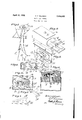
Figure 1 is a perspective view of a music rack having my device attached thereto,
Figure 2 is an enlarged perspective view showing the end of my device,
Figure 8 is a fragmentary perspective view of the actuating pawls,
Figure 4 is a cross sectional view of my device,
Figure 5 is an enlarged detail cross sectional view showing one of the positions of the actuating pawls,
Figure 6 is a similar view showing the raised position of the pawl carrier,
Figure 7 is a fragmentary perspective view of the end of the crank, and
Figure 8 is a side elevation of the foot bellows.
In the playing of sheet music which is positioned upon a music rack, it is necessary for a person to move the hands or at least one hand. from the instrument in order to turn the music or else it is necessary to have a second person present to accomplish the turn- 7 ing. Applicant has deviced a very simple mechanism wherein the player by simply manipulating a foot bellows can readily turn the page forward or backward.
In the accompanying drawings wherein for the purpose of illustration is shown a pre- 1930. Serial No. 451,767.
ferred embodiment of my invention, the numeral 5 designates a box-like structure having a hinged cover 6. This hinged cover has a downwardly extending plate 7 which is positioned at a point adjacent the end 8 of the box-like structure (see Figure 4). This plate 7 carries a pivoted transfer pawl 9 which has a depending tip 11, the purpose of which will be later seen. Pivoted as at 12 and 13 are looking pawls 14% and 16 respectively, which 4 are held in their normal position of Figure 3 by a spring 17. The ends of these pawls are spaced apart so as to provide a notch 18 into which the end 19 of a crank 21 is adapted to lie as shown in Figure 6. This crank is connected to a shaft 22 which has bearings in the front 8 of the box and an upstanding lug 28. An arm 24 is attached to the shaft 23 and carries clips 26 thereon, (see Figure 1). A bellows 27 is located within the box 5 and is connected by a tube 28 to a foot bellows 29. This bellows 27 is adapted to contact an adjacent screw 31.
Carried in the hinged cover 6 a spring 15 is secured to the box-like structure 5 and as its end passes thru a hole formed in the screw 31 with a result that the spring 15 tends to at all times hold the hinged cover 6 in its closed position so that when the bellows pushes thereagainst it will overcome the action of the spring and as soon as released, the spring will return the cover to crossed position.
The manner of operating my device is as follows Assuming that the same is attached to a music stand, as for instance, by a clamp 32, the parts will lie in position shown in Figure 5, and assuming that it is desired to turn the sheet, the Operator presses upon the bellows 29 which in turn opens the bellows 27 to dotted line posit-ion of Figure 4 which moves the hinged cover 6 and plate 7. This upward rising of the plate 7 causes the end 19 of the crank arm to ride upon either the cam A or the cam B depending upon which side the crank happens to be lying upon. As the end of the crank moves along the cam, the pawls 14 and 16, as the case may be, will be depressed until the end of the crank has arrived at the position shown in Figure 6. By
now releasing the pressure on the bellows, the hinged cover will drop, the end of the lever will then engage the transfer pawl 9 upon one side of the tip 11 and as it strikes the cam surface C it will throw the crank in that di rection. \Vhen the crank arrives at the end of its tr vel, as for instance assuming that the crank in Figure 6 is traveling toward the left of the drawing, it will arrive at the position shown in Figure 5 and will therefore tip the transfer pawl 9 to the full line position of this figure and as a consequence the same will be frictionally held in this position by a spring 34 so that the next time the end of the crank travels down the incline or cam A it will depress the end of the pawl 16 and come to rest in the notch 18 and upon the next release the end of the lever will engage the right hand side of the tip 11 and as a consequence the crank will be thrown to the opposite side of the device. As a result of this construction each operation and release of the bellows, the sheet attached to the clips 26 will be turned in either one direction or the other.
It is to be understood that the form of my invention herewith shown and described is to be taken as a preferred example of the same and that various changes relative to the material, size, shape and arrangement of parts may be resorted to without departing from the spirit of the invention or the scope of the subjoined claims.
Having thus described my invention, I claim 1. In a sheet turner, a box-like structure, a hinged cover attached thereto. a plate secured to said cover, pawls pivotally mounted on said plate, a crank arm carried by said boxlike structure and engaging a slot formed in said plate, said pivoted pawls being adapted to control the movement of said crank arm.
2. In a music sheet turner, a box-like structure, a. hinged cover attached thereto, a plate secured to said cover and extending into said box, pawls pivotally mounted on said plate, a slot formed in said plate, said slot having inclined surfaces, a crank arm pivoted to said box-like structure the end of said crank arm extending through said slot and engaging said pawls,an arm connected to said crank arm and a clip carried by said last mentioned arm for engaging sheet music in the manner described.
3. In a music sheet turner, a box-like structure, a hinged cover attached thereto, a plate secured to said cover and extending into said box, pawls pivotally mounted on said plate, a slot formed in said plate, said slot having inclined surfaces, a crank arm pivoted to said box-like structure, the end of said crank arm extending through said slot and engaging said pawls, an arm connected to said crank arm and a. clip carried by said last mentioned arm for engaging sheet music and means for actuating said hinged cover from a remote point.
at. In a music leaf turner, a box-like structure a hinged cover secured thereto, spring means positioned between said box-like structure and said cover for normally maintaining said cover in closed position, a plate secured to said cover and extending into said box, a pair of locking pawls pivotally mounted on said plate, a slot formed in said plate and having inclined cam surfaces, a crank arm pivot in said box-like structure and having its end extending thru said slot and adapted to engage said locking pawl, an arm connected to said crank arm, and a clip carried by said last mentioned arm for engaging sheet music a transfer pawl pivotally mounted on said plate, and means for actuating said. hinged cover against the tension of said spring from a remote point.
In testimony whereof I affix my signature.
ORESTE I RICIIEDA.
Priority Applications (1)
| Application Number | Priority Date | Filing Date | Title |
|---|---|---|---|
| US451767A US1854065A (en) | 1930-05-12 | 1930-05-12 | Music leaf turner |
Applications Claiming Priority (1)
| Application Number | Priority Date | Filing Date | Title |
|---|---|---|---|
| US451767A US1854065A (en) | 1930-05-12 | 1930-05-12 | Music leaf turner |
Publications (1)
| Publication Number | Publication Date |
|---|---|
| US1854065A true US1854065A (en) | 1932-04-12 |
Family
ID=23793606
Family Applications (1)
| Application Number | Title | Priority Date | Filing Date |
|---|---|---|---|
| US451767A Expired - Lifetime US1854065A (en) | 1930-05-12 | 1930-05-12 | Music leaf turner |
Country Status (1)
| Country | Link |
|---|---|
| US (1) | US1854065A (en) |
-
1930
- 1930-05-12 US US451767A patent/US1854065A/en not_active Expired - Lifetime
Similar Documents
| Publication | Publication Date | Title |
|---|---|---|
| US1854065A (en) | Music leaf turner | |
| US1190462A (en) | Music-sheet turner. | |
| US1329622A (en) | Device for turning over sheets of music | |
| US1482725A (en) | Target for amusement devices | |
| US1040209A (en) | Music-leaf turner. | |
| US902877A (en) | Music-leaf turner. | |
| US1346823A (en) | Rotatable wicket | |
| US581081A (en) | Music-leaf turner | |
| US1239006A (en) | Music-turner. | |
| US827970A (en) | Leaf-turning apparatus for books, music, &c. | |
| US574244A (en) | Music-leaf tui | |
| US1130108A (en) | Leaf-turner. | |
| US876781A (en) | Music-leaf turner. | |
| US1189154A (en) | Winding and rewinding mechanism. | |
| US1595220A (en) | Music-leaf turner | |
| US1288899A (en) | Music-leaf turner. | |
| US1028270A (en) | Music-sheet-turning device. | |
| US546519A (en) | Music-leaf turner | |
| US211604A (en) | Improvement in card and ticket cases | |
| US940003A (en) | Copy-holder. | |
| US2528289A (en) | Music-leaf turner | |
| US533039A (en) | Device for facilitating handling manuscript | |
| US783316A (en) | Music-leaf turner. | |
| US661895A (en) | Music-leaf turner. | |
| US885546A (en) | Music-turner. |