US1854056A - Circuit closer - Google Patents
Circuit closer Download PDFInfo
- Publication number
- US1854056A US1854056A US421461A US42146130A US1854056A US 1854056 A US1854056 A US 1854056A US 421461 A US421461 A US 421461A US 42146130 A US42146130 A US 42146130A US 1854056 A US1854056 A US 1854056A
- Authority
- US
- United States
- Prior art keywords
- arm
- contact
- steering wheel
- plunger
- arms
- Prior art date
- Legal status (The legal status is an assumption and is not a legal conclusion. Google has not performed a legal analysis and makes no representation as to the accuracy of the status listed.)
- Expired - Lifetime
Links
Images

Classifications
-
- B—PERFORMING OPERATIONS; TRANSPORTING
- B60—VEHICLES IN GENERAL
- B60Q—ARRANGEMENT OF SIGNALLING OR LIGHTING DEVICES, THE MOUNTING OR SUPPORTING THEREOF OR CIRCUITS THEREFOR, FOR VEHICLES IN GENERAL
- B60Q1/00—Arrangement of optical signalling or lighting devices, the mounting or supporting thereof or circuits therefor
- B60Q1/02—Arrangement of optical signalling or lighting devices, the mounting or supporting thereof or circuits therefor the devices being primarily intended to illuminate the way ahead or to illuminate other areas of way or environments
- B60Q1/04—Arrangement of optical signalling or lighting devices, the mounting or supporting thereof or circuits therefor the devices being primarily intended to illuminate the way ahead or to illuminate other areas of way or environments the devices being headlights
- B60Q1/14—Arrangement of optical signalling or lighting devices, the mounting or supporting thereof or circuits therefor the devices being primarily intended to illuminate the way ahead or to illuminate other areas of way or environments the devices being headlights having dimming means
- B60Q1/1446—Arrangement of optical signalling or lighting devices, the mounting or supporting thereof or circuits therefor the devices being primarily intended to illuminate the way ahead or to illuminate other areas of way or environments the devices being headlights having dimming means controlled by mechanically actuated switches
- B60Q1/1453—Hand actuated switches
- B60Q1/1461—Multifunction switches for dimming headlights and controlling additional devices, e.g. for controlling direction indicating lights
- B60Q1/1484—Multifunction switches for dimming headlights and controlling additional devices, e.g. for controlling direction indicating lights mounted on the steering wheel
Definitions
- This invention relates to improvements in vehicle direction signals and has especial relation to means for controlling the operation of the signal.
- An object of the present invention is the provision of an automobile signal which may be set to indicate a right or left turn, and which will be automatically restored to normal position at the completion of the turn, or may be manually reset prior 'to or without making the turn.
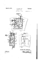
- Figure l is a plan view of the controlling switch showing a fragmentary portion of a steering wheel to which it is applied.
- Figure 2 is a section on the line 2 2 of Figure l.
- Figure 3 is a fragmentary plan view showing the Contact strips and the insulated housing therefor.
- FIGS 4 and 5 are fragmentary sectional views taken respectively on the lines 4 4 and 5 5 of Figure 3.
- Figure 6 is a horizontal sectional view illustrating the switch unit.
- Figure 7 is a section on the line 7 7 of Figure 6.
- Figure 8 is an inner plan view showing the switch unit.
- the mechanism mentioned comprises an annular relatively shallow transversely channel-shaped housing 22. rlhis housing .is formed of insulating material and has embedded therein spaced concentrically arranged annular contact strips 23. 24 and 25.
- the strip 23 is adapted to be connected in circuit with a left turn signal device, while the strip 25 is adapted to be connected in circuit f with a right turn signal device, the strip 24 being connected with a battery or other source of current and with each of the lamps.
- the lamps are included in open circuits and when the strips 23 and 24 are bridged, a circuit will be completed through the left Serial N' 421,461.
- the housing 22 which, as previously stated, is transversely channel-shaped, is provided around its edges with seats 26. These seats receive the opposite edges of an annular insulated cover 27 which is held for sliding rotary movement by means of narrow retaining bands 28.
- the cover 2'? is provided with an offset portieri 29 which forms a housing for a switch unit, and this housing is secured to the steering wheel 30 of an automobile through the medium of an attaching plate 31 and screws 32.
- the cover 27 will be rotated wit-hin the seat 2G of the housing.
- a plate 33 Secured within the oli'set portion 29 of the cover is a plate 33, the latter being held in place by screws 34, and by hollow bolts 35.
- Mounted for rotation in bushings 36 carried by the plate 33 are posts 3T and 38, the former having fast thereon a wing 39 and the latter having fast thereon a wing 40.
- Secured to the opposite ends of the posts 37 and 38 respectively are resilient contact arms L and R. These arms are normally spaced between the strips 23, 24 and 25, but the arm L when rotated to a position at right angles to that shown by dotted lines in Figure 6, will bridge the strips 23 and 24 and complete a circuit through a lamp to indicate a left turn. Likewise, when the arm R is moved to bridge the contacts 24 and 25. a lamp will be illuminated and a right turn indicated.
- the offset portion 29 of the cover 27 is provided with a bushing 41, and slidable through this bushing is a plunger rod 42.
- the inner end of this rod is provided with an offset foot 43 which is adapted to engage the wing 40, and when the plunger rod 42 depressed, to move this wing from the dotted to the full line position shown in Figure 6, whereupon the contact arm R will bridge the contacts 24 and 25 as previously stated.
- the arm R is yieldingly held in an active or inactive position by means of a spring 44, as shown in Figure 6 of the drawings.
- a spring 45 which is mounted upon the plunger rod 42 beneath an operating button 46 acts to return the plunger rod 42 to its normal position.
- the hollow bolts provide bearings for plunger rods 47 and 48. llhese rods are provided with operating buttons 49 and 50 respectively and are yieldinvly forced outward by means of springs l.
- the inner end of the plunger rod 47 carries branch arms 52 and 53, the arm 52 forming a stop tor the wing and limiting pivotal movement of the contact arm R in one direction.
- the wing 40 will be moved to move the spring 44' past the center and restore the contact arm R to its normally inactive position. In this position, the wing ⁇ 40 engages the foot 43V so that movement of the contact arm 40 is limited in this direction.
- the plunger rodA 48 is arranged in the path of movement of the wing 39 in one direction and acts as a stop to hold the contact arm L in neutral position. Also, the plunger rod 48 is adapted to be pushed inward to move the Wing 39 and the contact arm L into position to bridgethe strips 23 and 24, movement i-n this direction being limited by the arm 53 on the plunger 47. Thus, the plunger 47 may be'operated to return either the arm It or the arm L to neutral position independently or simultaneously. Stop pins 54 limit outward movement of the plunger rods.
- the right turn button 46 When it is desired to indicate a right turn, the right turn button 46 is pushed inward so thatthe contact arm B will bridge the contacts 24 and 25 as previously explained.
- the steering wheel is then operated in a clockwise direction and carries with it the switch unit, the right signal device being illuminated as soon as the button 46 is operated.
- one end of the contact arm R will ride over a tooth 55 which extends upward from the strip 25, so that when the turn is completed and the steering wheel straightened out, the arm R will be in a neutral position between the strips 24 and 25.
- the left signal device when the steering wheel is moved in an anti-clockwise direction to make a left turn, the left signal device will be illuminated. During this movement ot the steering wheel, the contact arm L will ride over a tooth 5.6 which extends upward from the strip 23, reverse movement ot ⁇ the steering wheel causing the arm L to engage this tooth, whereupon the arm will be returned to its normally inactive position.
- an automobile signal controlling switch a plurality of spaced stationary contact strips adapted to be connected in circuit with a signal device, a relatively movable switch unit adapted to be secured to the steering wheel ott an automobile, normally inactive independently movable contacts included in the movable switch unit, means to selectively move the contacts to bridge two of the contact strips and complete a circuit, spaced means arranged in the path ot the movable contacts to restore the latter to inactive position, and manually operated means to restore said movable contacts to inactive position.
- a stationary unit a movable unit slidingly associated therewith and adapted to be attached to the steering wheel of an automobile for movement therewith, said movable unit including pivotally mounted normally inactive contact arms, contact-s carried by the stationary unit tor engagement by said arms, a plunger for each contact arm to move said arms from an active to an inactive position, and; means to restore one or both of the pivotally mounted contact arms to an inactive position.
- a stationary unit a movable unit slidingly associated therewith and adapted to be attached to the steering wheel of an automobile for movement therewith, said movable unit including pivotally mounted normally inactive contact arms, contacts carried by the stationary unit tor engagement by said arms, a plunger for each contact arm to move said arms from an active to an inactive position, and a plunger common to both of the pivotally mounted contact arms to restore the latter to an inactive position.
Description
April l2, 1932. I A H, MQTT, JR 1,854,056
CIRCUIT CLOSER Filed Jan. 17,' 1930 2 Sheets-Sheet l mmimmllllllll za L Z4 it zz ATTORNEY WITNBS April 12, 1932. AH. MOTT', m
4 CIRCUIT CLOSER Filed Jan. 17, 1950 2 Sheets-Sheet 2 INVENTOR ATTORNEY Patented Apr. 12, 1932 ARTHUR H. MOTT, JR., OF DETROT, MICHIGAN CIRCUIT CLOSER Application filed January 17, 1930.
This invention relates to improvements in vehicle direction signals and has especial relation to means for controlling the operation of the signal.
An object of the present invention is the provision of an automobile signal which may be set to indicate a right or left turn, and which will be automatically restored to normal position at the completion of the turn, or may be manually reset prior 'to or without making the turn.
Vith the above and other objects in view, the invention further includes the following novel features and details of construction, to be hereinafter more fully described, illustrated in the accompanying drawings and pointed out in the appended claims.
In the drawings Figure l is a plan view of the controlling switch showing a fragmentary portion of a steering wheel to which it is applied.
Figure 2 is a section on the line 2 2 of Figure l.
Figure 3 is a fragmentary plan view showing the Contact strips and the insulated housing therefor.
Figures 4 and 5 are fragmentary sectional views taken respectively on the lines 4 4 and 5 5 of Figure 3.
Figure 6 is a horizontal sectional view illustrating the switch unit.
Figure 7 is a section on the line 7 7 of Figure 6.
Figure 8 is an inner plan view showing the switch unit.
The mechanism mentioned comprises an annular relatively shallow transversely channel-shaped housing 22. rlhis housing .is formed of insulating material and has embedded therein spaced concentrically arranged annular contact strips 23. 24 and 25. The strip 23 is adapted to be connected in circuit with a left turn signal device, while the strip 25 is adapted to be connected in circuit f with a right turn signal device, the strip 24 being connected with a battery or other source of current and with each of the lamps. Thus, the lamps are included in open circuits and when the strips 23 and 24 are bridged, a circuit will be completed through the left Serial N' 421,461.
signal device 2l to indicate a left turn, and when the strips 24 and 25 are bridged a circuit will be completed through the right signal device 2O and a right turn indicated.
The housing 22 which, as previously stated, is transversely channel-shaped, is provided around its edges with seats 26. These seats receive the opposite edges of an annular insulated cover 27 which is held for sliding rotary movement by means of narrow retaining bands 28.
The cover 2'? is provided with an offset portieri 29 which forms a housing for a switch unit, and this housing is secured to the steering wheel 30 of an automobile through the medium of an attaching plate 31 and screws 32. By this means when the steering wheel is rotated, the cover 27 will be rotated wit-hin the seat 2G of the housing.
Secured within the oli'set portion 29 of the cover is a plate 33, the latter being held in place by screws 34, and by hollow bolts 35. Mounted for rotation in bushings 36 carried by the plate 33 are posts 3T and 38, the former having fast thereon a wing 39 and the latter having fast thereon a wing 40. Secured to the opposite ends of the posts 37 and 38 respectively are resilient contact arms L and R. These arms are normally spaced between the strips 23, 24 and 25, but the arm L when rotated to a position at right angles to that shown by dotted lines in Figure 6, will bridge the strips 23 and 24 and complete a circuit through a lamp to indicate a left turn. Likewise, when the arm R is moved to bridge the contacts 24 and 25. a lamp will be illuminated and a right turn indicated.
ln order to move the arm Ft to an active position, the offset portion 29 of the cover 27 is provided with a bushing 41, and slidable through this bushing is a plunger rod 42. The inner end of this rod is provided with an offset foot 43 which is adapted to engage the wing 40, and when the plunger rod 42 depressed, to move this wing from the dotted to the full line position shown in Figure 6, whereupon the contact arm R will bridge the contacts 24 and 25 as previously stated. The arm R is yieldingly held in an active or inactive position by means of a spring 44, as shown in Figure 6 of the drawings. A spring 45 which is mounted upon the plunger rod 42 beneath an operating button 46 acts to return the plunger rod 42 to its normal position.
The hollow bolts provide bearings for plunger rods 47 and 48. llhese rods are provided with operating buttons 49 and 50 respectively and are yieldinvly forced outward by means of springs l. The inner end of the plunger rod 47 carries branch arms 52 and 53, the arm 52 forming a stop tor the wing and limiting pivotal movement of the contact arm R in one direction. In addition, by pushing the plunger rod 47 inward, the wing 40 will be moved to move the spring 44' past the center and restore the contact arm R to its normally inactive position. In this position, the wing` 40 engages the foot 43V so that movement of the contact arm 40 is limited in this direction.
The plunger rodA 48 is arranged in the path of movement of the wing 39 in one direction and acts as a stop to hold the contact arm L in neutral position. Also, the plunger rod 48 is adapted to be pushed inward to move the Wing 39 and the contact arm L into position to bridgethe strips 23 and 24, movement i-n this direction being limited by the arm 53 on the plunger 47. Thus, the plunger 47 may be'operated to return either the arm It or the arm L to neutral position independently or simultaneously. Stop pins 54 limit outward movement of the plunger rods.
When it is desired to indicate a right turn, the right turn button 46 is pushed inward so thatthe contact arm B will bridge the contacts 24 and 25 as previously explained. The steering wheel is then operated in a clockwise direction and carries with it the switch unit, the right signal device being illuminated as soon as the button 46 is operated. During this operation, one end of the contact arm R will ride over a tooth 55 which extends upward from the strip 25, so that when the turn is completed and the steering wheel straightened out, the arm R will be in a neutral position between the strips 24 and 25.
Likewise, when the steering wheel is moved in an anti-clockwise direction to make a left turn, the left signal device will be illuminated. During this movement ot the steering wheel, the contact arm L will ride over a tooth 5.6 which extends upward from the strip 23, reverse movement ot` the steering wheel causing the arm L to engage this tooth, whereupon the arm will be returned to its normally inactive position.
The invention is susceptible of various changes in its form, proportions and minor details of construction and the right is herein reserved to make such changes as properly fall Within the scope of the appended claims.
Having described the invention what is claimed is 1.[n an automobile signal controlling switch, a plurality of spaced stationary contact strips adapted to be connected in circuit with a signal device, a relatively movable switch unit adapted to be secured to the steering wheel ott an automobile, normally inactive independently movable contacts included in the movable switch unit, means to selectively move the contacts to bridge two of the contact strips and complete a circuit, spaced means arranged in the path ot the movable contacts to restore the latter to inactive position, and manually operated means to restore said movable contacts to inactive position.
2. In an automobile signal switch, a stationary unit, a movable unit slidingly associated therewith and adapted to be attached to the steering wheel of an automobile for movement therewith, said movable unit including pivotally mounted normally inactive contact arms, contact-s carried by the stationary unit tor engagement by said arms, a plunger for each contact arm to move said arms from an active to an inactive position, and; means to restore one or both of the pivotally mounted contact arms to an inactive position.
3. In an automobile signal switch, a stationary unit, a movable unit slidingly associated therewith and adapted to be attached to the steering wheel of an automobile for movement therewith, said movable unit including pivotally mounted normally inactive contact arms, contacts carried by the stationary unit tor engagement by said arms, a plunger for each contact arm to move said arms from an active to an inactive position, and a plunger common to both of the pivotally mounted contact arms to restore the latter to an inactive position.
ARTHUR H. MOTT, JR.
Priority Applications (1)
| Application Number | Priority Date | Filing Date | Title |
|---|---|---|---|
| US421461A US1854056A (en) | 1930-01-17 | 1930-01-17 | Circuit closer |
Applications Claiming Priority (1)
| Application Number | Priority Date | Filing Date | Title |
|---|---|---|---|
| US421461A US1854056A (en) | 1930-01-17 | 1930-01-17 | Circuit closer |
Publications (1)
| Publication Number | Publication Date |
|---|---|
| US1854056A true US1854056A (en) | 1932-04-12 |
Family
ID=23670614
Family Applications (1)
| Application Number | Title | Priority Date | Filing Date |
|---|---|---|---|
| US421461A Expired - Lifetime US1854056A (en) | 1930-01-17 | 1930-01-17 | Circuit closer |
Country Status (1)
| Country | Link |
|---|---|
| US (1) | US1854056A (en) |
Cited By (4)
| Publication number | Priority date | Publication date | Assignee | Title |
|---|---|---|---|---|
| US2673906A (en) * | 1951-07-11 | 1954-03-30 | United Specialties Co | Turn signal switch |
| US2920151A (en) * | 1957-01-24 | 1960-01-05 | Julius J Lawick | Door operating electric switch |
| US2993098A (en) * | 1958-09-29 | 1961-07-18 | Gen Motors Corp | Circuit controller |
| US5957442A (en) * | 1996-04-09 | 1999-09-28 | Hensley; Ralph | Turn signal spring |
-
1930
- 1930-01-17 US US421461A patent/US1854056A/en not_active Expired - Lifetime
Cited By (4)
| Publication number | Priority date | Publication date | Assignee | Title |
|---|---|---|---|---|
| US2673906A (en) * | 1951-07-11 | 1954-03-30 | United Specialties Co | Turn signal switch |
| US2920151A (en) * | 1957-01-24 | 1960-01-05 | Julius J Lawick | Door operating electric switch |
| US2993098A (en) * | 1958-09-29 | 1961-07-18 | Gen Motors Corp | Circuit controller |
| US5957442A (en) * | 1996-04-09 | 1999-09-28 | Hensley; Ralph | Turn signal spring |
Similar Documents
| Publication | Publication Date | Title |
|---|---|---|
| US1846513A (en) | Signaling system switch for automotive vehicles | |
| US1854056A (en) | Circuit closer | |
| US2284936A (en) | Direction indicator means | |
| US2152450A (en) | Switch | |
| US2432388A (en) | Directional signal system for vehicles | |
| US2249120A (en) | Direction signal operating means | |
| US2201795A (en) | Automatic traffic signal device | |
| US2226140A (en) | Automatic automobile directional signal | |
| US1584761A (en) | Switch | |
| US2144571A (en) | Automatic signal switch for automobiles | |
| US1668738A (en) | Indicator switch | |
| US2320641A (en) | Vehicle signal | |
| US1796695A (en) | Day and night thermostat | |
| US1850549A (en) | Automatic switch | |
| US2069936A (en) | Direction indicator switch | |
| US1896985A (en) | Automatic switch | |
| US1490005A (en) | Switch | |
| US2639339A (en) | Combination dimmer and direction switch | |
| US2021386A (en) | Automobile signal switch | |
| US1845267A (en) | Vehicle signal switch | |
| US1533295A (en) | Electric switch | |
| US2196113A (en) | Signaling device | |
| US1958057A (en) | Signal control | |
| GB504134A (en) | Improvements in or relating to the control of the lighting and the warning devices for vehicles | |
| US1753078A (en) | Switch for directional signals |