US1854048A - Nonreuseable coupling - Google Patents
Nonreuseable coupling Download PDFInfo
- Publication number
- US1854048A US1854048A US470169A US47016930A US1854048A US 1854048 A US1854048 A US 1854048A US 470169 A US470169 A US 470169A US 47016930 A US47016930 A US 47016930A US 1854048 A US1854048 A US 1854048A
- Authority
- US
- United States
- Prior art keywords
- union
- conduit
- coupling
- ratchet
- sections
- Prior art date
- Legal status (The legal status is an assumption and is not a legal conclusion. Google has not performed a legal analysis and makes no representation as to the accuracy of the status listed.)
- Expired - Lifetime
Links
- 230000008878 coupling Effects 0.000 title description 24
- 238000010168 coupling process Methods 0.000 title description 24
- 238000005859 coupling reaction Methods 0.000 title description 24
- 239000012530 fluid Substances 0.000 description 4
- 230000013011 mating Effects 0.000 description 4
- 230000000052 comparative effect Effects 0.000 description 1
- 238000010276 construction Methods 0.000 description 1
- 230000006378 damage Effects 0.000 description 1
- 238000001514 detection method Methods 0.000 description 1
- 238000006073 displacement reaction Methods 0.000 description 1
- 230000000694 effects Effects 0.000 description 1
- 230000004048 modification Effects 0.000 description 1
- 238000012986 modification Methods 0.000 description 1
Images
Classifications
-
- F—MECHANICAL ENGINEERING; LIGHTING; HEATING; WEAPONS; BLASTING
- F16—ENGINEERING ELEMENTS AND UNITS; GENERAL MEASURES FOR PRODUCING AND MAINTAINING EFFECTIVE FUNCTIONING OF MACHINES OR INSTALLATIONS; THERMAL INSULATION IN GENERAL
- F16L—PIPES; JOINTS OR FITTINGS FOR PIPES; SUPPORTS FOR PIPES, CABLES OR PROTECTIVE TUBING; MEANS FOR THERMAL INSULATION IN GENERAL
- F16L19/00—Joints in which sealing surfaces are pressed together by means of a member, e.g. a swivel nut, screwed on, or into, one of the joint parts
- F16L19/005—Joints in which sealing surfaces are pressed together by means of a member, e.g. a swivel nut, screwed on, or into, one of the joint parts comprising locking means for the threaded member
-
- F—MECHANICAL ENGINEERING; LIGHTING; HEATING; WEAPONS; BLASTING
- F16—ENGINEERING ELEMENTS AND UNITS; GENERAL MEASURES FOR PRODUCING AND MAINTAINING EFFECTIVE FUNCTIONING OF MACHINES OR INSTALLATIONS; THERMAL INSULATION IN GENERAL
- F16B—DEVICES FOR FASTENING OR SECURING CONSTRUCTIONAL ELEMENTS OR MACHINE PARTS TOGETHER, e.g. NAILS, BOLTS, CIRCLIPS, CLAMPS, CLIPS OR WEDGES; JOINTS OR JOINTING
- F16B39/00—Locking of screws, bolts or nuts
- F16B39/22—Locking of screws, bolts or nuts in which the locking takes place during screwing down or tightening
- F16B39/28—Locking of screws, bolts or nuts in which the locking takes place during screwing down or tightening by special members on, or shape of, the nut or bolt
- F16B39/32—Locking by means of a pawl or pawl-like tongue
-
- F—MECHANICAL ENGINEERING; LIGHTING; HEATING; WEAPONS; BLASTING
- F16—ENGINEERING ELEMENTS AND UNITS; GENERAL MEASURES FOR PRODUCING AND MAINTAINING EFFECTIVE FUNCTIONING OF MACHINES OR INSTALLATIONS; THERMAL INSULATION IN GENERAL
- F16B—DEVICES FOR FASTENING OR SECURING CONSTRUCTIONAL ELEMENTS OR MACHINE PARTS TOGETHER, e.g. NAILS, BOLTS, CIRCLIPS, CLAMPS, CLIPS OR WEDGES; JOINTS OR JOINTING
- F16B41/00—Measures against loss of bolts, nuts, or pins; Measures against unauthorised operation of bolts, nuts or pins
- F16B41/005—Measures against unauthorised operation of bolts, nuts or pins
-
- Y—GENERAL TAGGING OF NEW TECHNOLOGICAL DEVELOPMENTS; GENERAL TAGGING OF CROSS-SECTIONAL TECHNOLOGIES SPANNING OVER SEVERAL SECTIONS OF THE IPC; TECHNICAL SUBJECTS COVERED BY FORMER USPC CROSS-REFERENCE ART COLLECTIONS [XRACs] AND DIGESTS
- Y10—TECHNICAL SUBJECTS COVERED BY FORMER USPC
- Y10S—TECHNICAL SUBJECTS COVERED BY FORMER USPC CROSS-REFERENCE ART COLLECTIONS [XRACs] AND DIGESTS
- Y10S411/00—Expanded, threaded, driven, headed, tool-deformed, or locked-threaded fastener
- Y10S411/924—Coupled nut and bolt
- Y10S411/945—Cross key
- Y10S411/946—Spring-seated
-
- Y—GENERAL TAGGING OF NEW TECHNOLOGICAL DEVELOPMENTS; GENERAL TAGGING OF CROSS-SECTIONAL TECHNOLOGIES SPANNING OVER SEVERAL SECTIONS OF THE IPC; TECHNICAL SUBJECTS COVERED BY FORMER USPC CROSS-REFERENCE ART COLLECTIONS [XRACs] AND DIGESTS
- Y10—TECHNICAL SUBJECTS COVERED BY FORMER USPC
- Y10S—TECHNICAL SUBJECTS COVERED BY FORMER USPC CROSS-REFERENCE ART COLLECTIONS [XRACs] AND DIGESTS
- Y10S411/00—Expanded, threaded, driven, headed, tool-deformed, or locked-threaded fastener
- Y10S411/924—Coupled nut and bolt
- Y10S411/949—Rachet and bolt-carried pawl
Definitions
- This invention relates to couplings .and broadly comprehends a coupling which 1s so constructed that after its initial emplacement, a reuse thereof is positively precluded.
- the invention contemplates an improved coupling or union which, whilenotnecessarily restricted to such use, is primarily .devised for the connection of a fluid supply line to a meter for the purpose of preventing unauthorized disconnection of the supply line vfrom the meter and reconnection of the same therei with without detection.
- the invention resides 1n the provision of a union or coupling which may be initially emplaced to couple the parts, which coupling or union is constructed in such a manner and cooperates with one of said parts so as to prevent displacement without destruction of the union or'coupl1ng,"1t being understood that replacement couplings may be secured only from an authorized source.
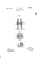
- Figure 1 is a longitudinal sectional view through a coupling or unionv constructed in accordance with the invention.
- Figure 2 is a transverse sectional view thereof taken approximately on the line 2-2 of Figure 1 ⁇
- Figure 3 is a perspective view of the coupling element removed.
- the means consist of one or more ratchet pawls 10 carried by and normally projecting from the threaded conduit section 6 and engageable with ratchet grooves 11 extending axially of the internally threaded portion 9 and spaced circumferentially.
- the coupling element or union 8 is formed with external wrench or tool engaging surfaces 12 having cut-away vor weakened portions i 18 atv a point adjacent the ratchet grooves 11 so that upon theapplication of a sufficient force to turn the element or union 8 in a direction to uncouple the sections 5 and 6, the element or union 8 will befractured and rendered unfit for reuse.
- y assembling the ratchet pawls 10 may be em'- ployed but for the purpose of illustration a tube section 14 has been shown which', is arranged diametrically within the Ythreaded conduit section 6 to axially align with ldiametrically disposed openings 15 which are of a lesser diameter than the interior diams eter of the tube section 14.
- the ratchet pawls 10 are designed to snugly fit the openings15 and are provided with enlarged inner.
- a pair of mating communicating fluid conduit Sectio-ns a union carried by and swiveled on one of the conduit sections and threadedly engaging the other conduit section and interengaging means on said union and the latter conduit section for fracturing said union upon retrograde turnthat in use of the Y device for connecting a fluid supply line to a Y ing movement thereof for the purpose of disconnecting the conduit sections, said means including a ratchet pawl carried by and normally projecting from the threaded conduit section and ratchet grooved portions on the union cooperating with the pawl to permit of free turning movement of the union to thread unto the threaded conduit section and weakened portions of said union.
- a pair of mating communicating iuid conduit sections a union carried by and swiveled on one of the conduit sections and threadedly engaging the other conduitsection and interengaging means on said union and the latter conduit section for fracturing said union upon retrograde turning movement thereof for the purpose of disconnecting the conduit sections
- said means including a ratchet pawl carried by and normally projecting from the threaded conduit section and ratchet grooved portions on the union cooperating with the pawl to permit of free turning movement of the union to thread onto the threaded conduit section and weakened portions of said union disposed adjacent the ratchet grooved portions thereof.
- a non-reuseable coupling having weakened portions adapted to be fractured upon uncoupling thereof, 'and means adapted to cooperate with one of a plurality of elements to be Coupled for causing fracturing of said coupling upon relative movement thereof with reference to said element when attempting to uncouple the same.
Landscapes
- Engineering & Computer Science (AREA)
- General Engineering & Computer Science (AREA)
- Mechanical Engineering (AREA)
- Quick-Acting Or Multi-Walled Pipe Joints (AREA)
Description
April 12, 1932.E J. J. LAUSTER L1,854,043
NONREUSEABLE COUPLINGv Filed July 23, 1930 Edf l V W l H W4, 2
mummy-emma f if J0 7 i 9 ji mvENToR wxTNEssEs .707m .ZLausZer BY a ification and accompanying Patented Apr. l2, 1932 UNITE STATES PATENT orifice JOHN J'. LA'CI'SLEIB,2 NEW YORK, N. "Y., ASSIGNOR TO GEORGE T. RITCHINGS, OF
MAPLEWOOD, NEW JERSEY NONREUSEABLE ooUPLING Application led July 23,
This invention relates to couplings .and broadly comprehends a coupling which 1s so constructed that after its initial emplacement, a reuse thereof is positively precluded.
The invention contemplates an improved coupling or union which, whilenotnecessarily restricted to such use, is primarily .devised for the connection of a fluid supply line to a meter for the purpose of preventing unauthorized disconnection of the supply line vfrom the meter and reconnection of the same therei with without detection.
More specifically the invention resides 1n the provision of a union or coupling which may be initially emplaced to couple the parts, which coupling or union is constructed in such a manner and cooperates with one of said parts so as to prevent displacement without destruction of the union or'coupl1ng,"1t being understood that replacement couplings may be secured only from an authorized source.
Other objects of the invention reside in'V the comparative simplicity of lthe construction of the coupling or union, the economy with which it may be produced and the general eliciency derived therefrom.
lVith the above recitedfand other objects in view, reference is had to the following specdrawings in which there is illustrated one embodiment of the invention, while the claims define the actual scope thereof.
In the drawings: y
Figure 1 is a longitudinal sectional view through a coupling or unionv constructed in accordance with the invention.
Figure 2 is a transverse sectional view thereof taken approximately on the line 2-2 of Figure 1` Figure 3 is a perspective view of the coupling element removed.
Referring to the drawings by characters of reference. 5 and 6 designate respectively a pair of conduit sections, the latter being eX- ternally threaded as at 7 and the former having swiveled thereon a coupling element or union 8 which is internally threaded as threaded portion 7 of the conduit section 6 1930. serial No. 470,169.
movement of the 'element8 inthe opposite direction to uncouple or tions 5 and 6. Y
Preferably the means consist of one or more ratchet pawls 10 carried by and normally projecting from the threaded conduit section 6 and engageable with ratchet grooves 11 extending axially of the internally threaded portion 9 and spaced circumferentially. The coupling element or union 8 is formed with external wrench or tool engaging surfaces 12 having cut-away vor weakened portions i 18 atv a point adjacent the ratchet grooves 11 so that upon theapplication of a sufficient force to turn the element or union 8 in a direction to uncouple the sections 5 and 6, the element or union 8 will befractured and rendered unfit for reuse.
Obviously, y assembling the ratchet pawls 10 may be em'- ployed but for the purpose of illustration a tube section 14 has been shown which', is arranged diametrically within the Ythreaded conduit section 6 to axially align with ldiametrically disposed openings 15 which are of a lesser diameter than the interior diams eter of the tube section 14. The ratchet pawls 10 are designed to snugly fit the openings15 and are provided with enlarged inner. ends 16 which snugly lit within the tube section 14 thereby providing a stop shoulder 17 which limits the outward movement of the ratchet pawls under the influence of a coiled expansion spring 18 yarranged in the tube and interposed within the enlarged in-k ner ends 16 of the pawls. c c
In use of the device it is apparent that coupling of the conduit 5 with the conduit 6 is accomplished by turning the. element or union 8 in a clockwise direction as indicated by the arrow in Figure 2,. thereby screwing said element or union 8 onto the threaded disconnect the secvarious ways of mounting and municating end 7 of the conduit 6. The ratchet grooves Will freely ratchet over and cam the ratchet pawls l0 inwardly until the connection is established. Any attempt to turn the union or element 8 in a counterclockwise direction will result in fracturing of the element or union 8 at the weakened portions 13 if sufficient force is exerted.
It is, therefore, obvious meter attempts to disconnect and reconnect the supply line and meter for fraudulent purposes will be readily detected in view of the fact that unauthorized persons cannot secure a new union or coupling` element 8 to replace the one which is fractured.
VWhile there has been illustrated and described a single and preferred embodiment of the invention, it is to be clearly understood that no limitation is intended to the precise structural details and that variations and modifications thereof, which properly fall within the scope of the appended claims, may be resorted to when desired.
I claim:
l. The combination with a pair of conduit sections, of non-reuseable coupling element therefor, carried by one of the sections and movable in o-ne direction relative to the other section for effecting coupling of said sections, said element and latter section having interengaging means for fracturing the coupling element upon relative movement in the other direction.
2. In combination, a pair of mating co-mmunicating fluid conduit Sections, a union carried by and swiveled on one of the conduit sections and threadedly engaging the other conduit section and inter-engaging means on said union and the latter conduit section for fracturing said union upon retrograde turning movement thereof for the purpose of disconnecting the conduit sections.
3. In combination, a pair of mating comfluid conduit sections, a union carried by and swiveled on one of the conduit sectionsand threadedly engaging the other conduit Section and interengaging means on said union and the latter conduit section for fracturing said union upon retrograde turning movement thereof for the purpose of disconnecting the. conduit sections, said means including a ratchet pawl carriedby and normally projecting from the threaded conduit section and ratchet grooved portions on the union cooperating with the pawl to permit of free turning movement of the union to thread onto the threaded conduit section.
4. In combination, a pair of mating communicating fluid conduit Sectio-ns, a union carried by and swiveled on one of the conduit sections and threadedly engaging the other conduit section and interengaging means on said union and the latter conduit section for fracturing said union upon retrograde turnthat in use of the Y device for connecting a fluid supply line to a Y ing movement thereof for the purpose of disconnecting the conduit sections, said means including a ratchet pawl carried by and normally projecting from the threaded conduit section and ratchet grooved portions on the union cooperating with the pawl to permit of free turning movement of the union to thread unto the threaded conduit section and weakened portions of said union.
5. In combination, a pair of mating communicating iuid conduit sections, a union carried by and swiveled on one of the conduit sections and threadedly engaging the other conduitsection and interengaging means on said union and the latter conduit section for fracturing said union upon retrograde turning movement thereof for the purpose of disconnecting the conduit sections, said means including a ratchet pawl carried by and normally projecting from the threaded conduit section and ratchet grooved portions on the union cooperating with the pawl to permit of free turning movement of the union to thread onto the threaded conduit section and weakened portions of said union disposed adjacent the ratchet grooved portions thereof.
6. In combination, an externally threaded conduit, a second conduit communicating therewith, ian internally threaded coupling element swiveled on the'second conduit and threadedly engaging the first to connect said conduits, said coupling element and first conduit having coacting means for effecting the fracturing of the former upon disconnection of the conduits.
7. A non-reuseable coupling having weakened portions adapted to be fractured upon uncoupling thereof, 'and means adapted to cooperate with one of a plurality of elements to be Coupled for causing fracturing of said coupling upon relative movement thereof with reference to said element when attempting to uncouple the same.
8. The combination with a pair of members to be coupled, of a non-reuseable coupling movable in one direction with reference to said members to effect coupling thereof, said coupling element and one of said sections having cooperative means for 'fracturing the coupling element upon relative. movement in an opposite direction.
Signed at Jamaica, N. Y., in the county of Queens and State of New York, this 21st day of July, 1930.
JOHN J. LAUSTER.
Priority Applications (1)
| Application Number | Priority Date | Filing Date | Title |
|---|---|---|---|
| US470169A US1854048A (en) | 1930-07-23 | 1930-07-23 | Nonreuseable coupling |
Applications Claiming Priority (1)
| Application Number | Priority Date | Filing Date | Title |
|---|---|---|---|
| US470169A US1854048A (en) | 1930-07-23 | 1930-07-23 | Nonreuseable coupling |
Publications (1)
| Publication Number | Publication Date |
|---|---|
| US1854048A true US1854048A (en) | 1932-04-12 |
Family
ID=23866546
Family Applications (1)
| Application Number | Title | Priority Date | Filing Date |
|---|---|---|---|
| US470169A Expired - Lifetime US1854048A (en) | 1930-07-23 | 1930-07-23 | Nonreuseable coupling |
Country Status (1)
| Country | Link |
|---|---|
| US (1) | US1854048A (en) |
Cited By (5)
| Publication number | Priority date | Publication date | Assignee | Title |
|---|---|---|---|---|
| US2758625A (en) * | 1952-12-05 | 1956-08-14 | Illinois Tool Works | Fastener comprising a threaded receptacle, co-operating threaded stud and spring detent locking means thereon |
| US2869881A (en) * | 1957-11-27 | 1959-01-20 | Frederick H Smith | Adjustable floating tool holders |
| US3153547A (en) * | 1960-08-11 | 1964-10-20 | Forrest E Chancellor | Hydraulically releasable casing connector |
| US4436273A (en) | 1980-12-16 | 1984-03-13 | Nifco Inc. | Fastening means for rearview mirror in automobile interior |
| US5611653A (en) * | 1995-02-06 | 1997-03-18 | Al-Ko Kober Corporation | Spindle having lubrication and nut retention means |
-
1930
- 1930-07-23 US US470169A patent/US1854048A/en not_active Expired - Lifetime
Cited By (5)
| Publication number | Priority date | Publication date | Assignee | Title |
|---|---|---|---|---|
| US2758625A (en) * | 1952-12-05 | 1956-08-14 | Illinois Tool Works | Fastener comprising a threaded receptacle, co-operating threaded stud and spring detent locking means thereon |
| US2869881A (en) * | 1957-11-27 | 1959-01-20 | Frederick H Smith | Adjustable floating tool holders |
| US3153547A (en) * | 1960-08-11 | 1964-10-20 | Forrest E Chancellor | Hydraulically releasable casing connector |
| US4436273A (en) | 1980-12-16 | 1984-03-13 | Nifco Inc. | Fastening means for rearview mirror in automobile interior |
| US5611653A (en) * | 1995-02-06 | 1997-03-18 | Al-Ko Kober Corporation | Spindle having lubrication and nut retention means |
Similar Documents
| Publication | Publication Date | Title |
|---|---|---|
| US2631872A (en) | Quick coupling | |
| US2122757A (en) | Drill stem coupling | |
| US1414207A (en) | Shaft coupling | |
| US1729483A (en) | Coupling for pipes or conduits | |
| US1854048A (en) | Nonreuseable coupling | |
| US1134179A (en) | Coupling. | |
| US808446A (en) | Coupling. | |
| US1089650A (en) | Hose-coupling. | |
| US1324654A (en) | Vania | |
| US1212817A (en) | Hose-coupling. | |
| US1460154A (en) | Pipe coupling | |
| US1694056A (en) | Locking plug for extension cords | |
| US1889867A (en) | Tubular coupling | |
| US921368A (en) | Hose-coupling. | |
| US1134092A (en) | Pipe-joint. | |
| US1020258A (en) | Swivel-joint hose-coupling. | |
| US112958A (en) | Improvement in pipe-couplings | |
| US1903736A (en) | Nonreusable coupling | |
| US1822140A (en) | Plug for oil wells and apparatus for seating the same | |
| US832757A (en) | Hose-coupling. | |
| US1596645A (en) | Detachable coupling | |
| US331170A (en) | Dlesex | |
| US1712273A (en) | Pipe coupling | |
| US932162A (en) | Protective device for gas-meters. | |
| US1805321A (en) | Pipe coupling or connection |