US1854042A - Vacuum cleaning machine - Google Patents
Vacuum cleaning machine Download PDFInfo
- Publication number
- US1854042A US1854042A US89647A US8964726A US1854042A US 1854042 A US1854042 A US 1854042A US 89647 A US89647 A US 89647A US 8964726 A US8964726 A US 8964726A US 1854042 A US1854042 A US 1854042A
- Authority
- US
- United States
- Prior art keywords
- brush
- casing
- housing
- passage
- secured
- Prior art date
- Legal status (The legal status is an assumption and is not a legal conclusion. Google has not performed a legal analysis and makes no representation as to the accuracy of the status listed.)
- Expired - Lifetime
Links
- 238000010407 vacuum cleaning Methods 0.000 title description 7
- 239000000428 dust Substances 0.000 description 10
- 238000010276 construction Methods 0.000 description 4
- 230000005484 gravity Effects 0.000 description 3
- 238000010408 sweeping Methods 0.000 description 2
- 238000005266 casting Methods 0.000 description 1
- 238000004140 cleaning Methods 0.000 description 1
- JHIVVAPYMSGYDF-UHFFFAOYSA-N cyclohexanone Chemical compound O=C1CCCCC1 JHIVVAPYMSGYDF-UHFFFAOYSA-N 0.000 description 1
- 210000005069 ears Anatomy 0.000 description 1
- 239000002184 metal Substances 0.000 description 1
- 238000005192 partition Methods 0.000 description 1
Images


Classifications
-
- A—HUMAN NECESSITIES
- A47—FURNITURE; DOMESTIC ARTICLES OR APPLIANCES; COFFEE MILLS; SPICE MILLS; SUCTION CLEANERS IN GENERAL
- A47L—DOMESTIC WASHING OR CLEANING; SUCTION CLEANERS IN GENERAL
- A47L5/00—Structural features of suction cleaners
- A47L5/12—Structural features of suction cleaners with power-driven air-pumps or air-compressors, e.g. driven by motor vehicle engine vacuum
- A47L5/22—Structural features of suction cleaners with power-driven air-pumps or air-compressors, e.g. driven by motor vehicle engine vacuum with rotary fans
- A47L5/28—Suction cleaners with handles and nozzles fixed on the casings, e.g. wheeled suction cleaners with steering handle
- A47L5/34—Suction cleaners with handles and nozzles fixed on the casings, e.g. wheeled suction cleaners with steering handle with height adjustment of nozzles or dust-loosening tools
Definitions
- VACUUM CLEANING MACHINE File d Feb. 20, 1926 5 Sheets-Sheet 4 April 12, 1932.
- My invention relates to new and useful improvements in vacuum cleaners and has for its principal object the provision of a cleaner of this character which is relatively simple and inexpensive in construction, which is relatively light so that it may be easily carr ed from place to place, and which is so constructed as to efficiently gather the dirt from a floor or other object to be cleaned.
- Another obj ect of the invention consists in providing a cleaner of the character described with a rotatable brush and so mounting the brush that it may be adjusted to compensate for wear, the brush being pivotally connected within the nozzle chamber or housing whereby it will fall by gravity to contact w1th the surface being cleaned at all times.
- a further object resides in forming a 11p on each side of the nozzle openingfor reducing the velocity of the air by frict1on.
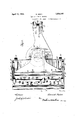
- Fig. 1 is a top plan.
- Fig. 2 is a bottom plan.
- Fig. 3 is a side elevation with parts shown in section.
- Fig. 4 is a horizontal section with parts shown in plan.
- Fig. 5 is a side elevation, with parts shown in section, of a slightly modified form of the invention.
- Fig. 6 is a fragmental bottom construction shown in Fig. 5.
- FIG. 1 indicates the base or nozzle housing or casing which consists of the top 2, the bottom 3, the sides 4 and 5, the rear wall 6, and the arcuate shaped front wall 7.
- a substantially circular wall or partition 8 which forms a housing for a rotataplan of the ble brush 9 and forms between the front wall 7 and the end of the bottom 3 the two nozzle passages shown at 9 and 10, each of the passages 9 and 10 communicating with the passage 11, at the top of the housing or casing 1.
- the rear end of the passage 11 communicateswith the fan casing 12, formed on or secured to the top of the housing or casing 1 and secured to the top of the fan casing 12 by the screws 13 or similar fastening means is a motor housing 14 in which is supported an electric motor not shown.
- Extending from and communicating with'the fan casing 12 is the extension or outlet 15 to which will be secured the dust bag 16.
- the metal thimble or sleeve 17 Secured to the lower end of the dust bag 16 is the metal thimble or sleeve 17 having the bayonette slot 18 to receive the lug or pin 19 secured to or formed on the extension or outlet 15.
- the rear portion of the housing or casing 1 is preferably detachable, for a purpose which will be presently described, and this rear portion is secured to the main portion by means of the screws 20 or similar fastenings.
- each of the side walls 4 and 5 Formed on the inner face of each of the side walls 4 and 5, adjacent the rear end, is an interiorly threaded lug or boss 21 to which the supporting wheels 22 are adapted to be rotatably connected by means of the screws, bolts, or similar means 23.
- a plate or bearing 24- Secured to the under side of the extension or outlet passage 15 is a plate or bearing 24- to which is swiveled the fork 25 carrying the wheel or casting 26.
- the brush 9, previously described, is carried upon the horizontal shaft 27 which is supported at each end in the bearings 28, the bearings being carried by the arms or links 29 which are pivoted at their rear ends to the sides of the housing or casing by means of the studs 30. While balls are not shown the bearings are preferably ball bearings.
- An extension 31 is formed on the rear endof each of the arms or links 29 and are so positioned that when the forward ends of the arms or links, carrying the brush, are lowered to the desired degree they will engage the lugs or bosses 21 and thereby prevent further downward movement.
- the brush 9 is of such a diameter as to contact with the surface to be cleaned between the nozzle passages 9' and 10.
- a pulley1 32 is secured to the brush shaft 27, interme 'ate the ends thereof, to receive the driving belt 33 which is operated in a manner to be later described.
- a lip 34 of suflicient width Formed on each side of the nozzle passage 10 is a lip 34 of suflicient width that when the cleaner is in use for cleaning a carpet 35 or the like the carpet will be drawn up by the air into contact with the passage as shown more particularly in Fig. 3 of the drawings but will not contact with the entire under surfaces of the lips, leaving a passage 36 between the carpet or other member and the under surface of the lips so that air may pass therebetween.
- These lips being formed and operating as described reduce the velocity of the air by friction. This is done by drawing the air, or forcing the air to travel, between the lips and the carpet or other member being cleaned and then working through the pile of the carpet and into the nozzle passage.
- the carpet or other member is drawn up to the nozzle passage and leaves a slight opening or space on each side.
- the velocity of the air it is not reduced sufiiciently to impair the efficiency because it allows for a larger volume of air to pass through the nap of the carpet or rug which means that a larger amount of dust is extracted from the carpet or rug.
- the bearings 37 Secured within the rear portion of the housing or casing 1 are the bearings 37 which support the countershaft 38, intermediate the ends of which is secured the worm gear 3. Secured to one end of the counter shaft 38 is the pulley 40 around which operates the belt 33.
- an electric motor is operable in the motor housing 14 and secured to and operated by the motor is the depending shaft 41 to which is secured the fan 42 adapted to operate in the fan casing 12. Adjacent the lower end of the shaft 41 is secured the worm 43 adapted to mesh with the worm gear 39.
- transversely spaced pairs of lugs or ears 44 are Formed on or secured to the top 2 of the housing or casing 1 to which is pivotally connected the handle 45.
- the cleaner may be moved over the surface to be cleaned by the handle 45 and the entire device is of such a weight that it may be easily pushed over the surface or may be raised and carried from place to place.
- the dust bag 16 is detachably connected to the extension or outlet 15 by means of the ilgeeve 17 engaging with the pin or projection
- Figs. 5 and 6 of the drawings I have illustrated a slightly modified form of the invention wherein but a single nozzle passageor inlet is formed.
- the base or nozzle housing or casing is shown at 46, the fan casing at 47, and the motor housing at 48.
- the nozzle passage 49 On each side of which is formed a lip 50 for the same purpose as pointed out for the preferred form of the invention.
- An extension 54 is formed on each of the arms or links 52 for the same purpose as described for the preferred embodiment of the invention and are adapted to engage a lug or stud 55.
- the brush is rotated in the same manner as described for the preferred form of the invention and all dust and litter enters the nozzle passage 49 and is drawn rearwardly by means of the fan operating in the fan casing 47.
- the dust or litter is discharged into the dust bag 16.
- the brush will always contact with the carpet, rug or other surface being cleaned and as the bristles'of the brush wear away the brush will drop by gravity.
- the carpet or rug will be drawn up on either side of the brush, by suction, into contact with the nozzle and with the space left between the surface ion wooden or like floors as well as on carpets, rotating the brush.
- my improved form of machine will be adapted for use on s or the like, and may both clean and ru poish such floors. At times where'rugs or the like do not entirely cover a floor surfaceit is necessar that both the ru surface and the floor sur ace be cleaned an my machine will allow this to be done.
- the rotation of the brush will not only clean a floor but will polish the same and as the brush rotates at a relatively low speed the floor will not be injured.
- a vacuum cleaner having spaced air in let passages with a brush housing formed therebetween, a brush rotatably mounted within the housing, the lower opening of one means extendin inwardly of the casing and positioned relative to the extensions of the arms to be engaged thereby for limiting the pivotal movement of the arms, and means for In testimony whereof I hereunto afiix my signature.
- passages being directed towards the lower portion of the brush to receive the sweepings therefrom and the surfaces on opposite sidesof the lower opening of the other passage being substantially. horizontal to be engaged by the article being cleaned, and means for rotating the brush so that its lower portion moves toward the lower opening of the first mentioned passage.
- a vacuum cleaner having spaced air inlet passages with a brush housing formed therebetween, a brush rotatably mounted within the housing, the lower opening of one of said passages being directed towards the 'lower portion of the brush to receive the sweepings therefrom, wide substantially horizontal lips formed on opposite sides of the lower openin of the other passage and extending longitudinally thereof, portions of the lips being adapte to be engaged by the article being cleaned, and means for rotating the brush so that its lower portion moves toward the lower opening of the first mentioned passage.
- a vacuum cleaner including a casing having an air passage therein, arms pivotally connected to the interior of the casing a brush carried by the arms on one side o the pivots, a rearwardly directed extension formed on each of the arms on the oppos te side of the ivots, projections extending 11 ⁇ - wardly of t e casing in position to overhe the extensions, said projections allowing normal pivotal movement of the arms but adapted to be engaged to limit downward swinging movement thereof, and means for rotating the brush.
- a vacuum cleaner including a casing having an air passage therein, arms pivotally connected to the casing, a brush carried by the arms on one side of the pivot, a rearwardly directed extension formed on of the arms on the opposite side of the pivot,
Landscapes
- Nozzles For Electric Vacuum Cleaners (AREA)
Description
April 12, 1932. B, KER 1,854,042
VACUUM CLEANING MACHINE 5 Sheets-Sheet l i anon stow.-
awuenfoz:
ifwmd 4 v 4. v
April 12, 1932.
April 12, 1932. B. KERN VACUUM CLEANING MACHINE Filed Feb. 20, 1926 5 Sheets-Sheet 5 April 12, 1932. KERN 6 1,854,042
VACUUM CLEANING MACHINE File d Feb. 20, 1926 5 Sheets-Sheet 4 April 12, 1932.
B. KERN I VACUUM CLEANING MACHINE Filed Feb. 20,
5 Sheets-She't 5 Patented Apr. 12, 1 932 PATENT OFFICE BERNARD KERN, OF SYRACUSE, NEW YORK VACUUM CLEANING MACHINE Application filed February 20, 1928. Serial No. 89,647.
My invention relates to new and useful improvements in vacuum cleaners and has for its principal object the provision of a cleaner of this character which is relatively simple and inexpensive in construction, which is relatively light so that it may be easily carr ed from place to place, and which is so constructed as to efficiently gather the dirt from a floor or other object to be cleaned.
Another obj ect of the invention consists in providing a cleaner of the character described with a rotatable brush and so mounting the brush that it may be adjusted to compensate for wear, the brush being pivotally connected within the nozzle chamber or housing whereby it will fall by gravity to contact w1th the surface being cleaned at all times.
A further object resides in forming a 11p on each side of the nozzle openingfor reducing the velocity of the air by frict1on.
With the above and other objects in vlew, which will appear as the description proceeds, my invention consists in the novel details of construction, and arrangement of parts, de-
scribed in the following specification and illustrated in the accompanying drawings, and while I have illustrated and described the preferred embodiments of the invention, as they now appear to me, it will be understood that such changes may be made as will fall within the scope of the appended claims.
In the drawings Fig. 1 is a top plan.
Fig. 2 is a bottom plan.
Fig. 3 is a side elevation with parts shown in section.
Fig. 4 is a horizontal section with parts shown in plan.
Fig. 5 is a side elevation, with parts shown in section, of a slightly modified form of the invention; and
Fig. 6 is a fragmental bottom construction shown in Fig. 5.
In the drawings 1 indicates the base or nozzle housing or casing which consists of the top 2, the bottom 3, the sides 4 and 5, the rear wall 6, and the arcuate shaped front wall 7. Formed within the housing or cas ing is a substantially circular wall or partition 8 which forms a housing for a rotataplan of the ble brush 9 and forms between the front wall 7 and the end of the bottom 3 the two nozzle passages shown at 9 and 10, each of the passages 9 and 10 communicating with the passage 11, at the top of the housing or casing 1. The rear end of the passage 11 communicateswith the fan casing 12, formed on or secured to the top of the housing or casing 1 and secured to the top of the fan casing 12 by the screws 13 or similar fastening means is a motor housing 14 in which is supported an electric motor not shown. Extending from and communicating with'the fan casing 12 is the extension or outlet 15 to which will be secured the dust bag 16. Secured to the lower end of the dust bag 16 is the metal thimble or sleeve 17 having the bayonette slot 18 to receive the lug or pin 19 secured to or formed on the extension or outlet 15. The rear portion of the housing or casing 1 is preferably detachable, for a purpose which will be presently described, and this rear portion is secured to the main portion by means of the screws 20 or similar fastenings.
Formed on the inner face of each of the side walls 4 and 5, adjacent the rear end, is an interiorly threaded lug or boss 21 to which the supporting wheels 22 are adapted to be rotatably connected by means of the screws, bolts, or similar means 23. Secured to the under side of the extension or outlet passage 15 is a plate or bearing 24- to which is swiveled the fork 25 carrying the wheel or casting 26.
The brush 9, previously described, is carried upon the horizontal shaft 27 which is supported at each end in the bearings 28, the bearings being carried by the arms or links 29 which are pivoted at their rear ends to the sides of the housing or casing by means of the studs 30. While balls are not shown the bearings are preferably ball bearings. An extension 31 is formed on the rear endof each of the arms or links 29 and are so positioned that when the forward ends of the arms or links, carrying the brush, are lowered to the desired degree they will engage the lugs or bosses 21 and thereby prevent further downward movement. As shown in the drawings the brush 9 is of such a diameter as to contact with the surface to be cleaned between the nozzle passages 9' and 10. A pulley1 32 is secured to the brush shaft 27, interme 'ate the ends thereof, to receive the driving belt 33 which is operated in a manner to be later described.
Formed on each side of the nozzle passage 10 is a lip 34 of suflicient width that when the cleaner is in use for cleaning a carpet 35 or the like the carpet will be drawn up by the air into contact with the passage as shown more particularly in Fig. 3 of the drawings but will not contact with the entire under surfaces of the lips, leaving a passage 36 between the carpet or other member and the under surface of the lips so that air may pass therebetween. These lips being formed and operating as described reduce the velocity of the air by friction. This is done by drawing the air, or forcing the air to travel, between the lips and the carpet or other member being cleaned and then working through the pile of the carpet and into the nozzle passage. It will be noted, as previously stated, that the carpet or other member is drawn up to the nozzle passage and leaves a slight opening or space on each side. In reducing the velocity of the air it is not reduced sufiiciently to impair the efficiency because it allows for a larger volume of air to pass through the nap of the carpet or rug which means that a larger amount of dust is extracted from the carpet or rug.
Secured within the rear portion of the housing or casing 1 are the bearings 37 which support the countershaft 38, intermediate the ends of which is secured the worm gear 3. Secured to one end of the counter shaft 38 is the pulley 40 around which operates the belt 33. As has been previously stated an electric motor, not shown, is operable in the motor housing 14 and secured to and operated by the motor is the depending shaft 41 to which is secured the fan 42 adapted to operate in the fan casing 12. Adjacent the lower end of the shaft 41 is secured the worm 43 adapted to mesh with the worm gear 39.
Formed on or secured to the top 2 of the housing or casing 1 are the transversely spaced pairs of lugs or ears 44 to which is pivotally connected the handle 45.
From the above detail description it is thought that the construction and operation will be understood. The rotation of the shaft 41 by the motor rotates the countershaft 38 through means of the worm 43 and worm gear 39. The belt 33 is operated from the pulley 40 on the countershaft and in turn rotates the brush 9 in the direction of the arrow Fig. 3. The brush loosens the litter on the surface to be cleaned and throws it towards the nozzle passage 9 through which it is drawn by suction created by the fan 42. The dust will be drawn out of the nap of the carpet or rug into the nozzle passage 10 by the suction of the fan 42 and all dust and litter is discharged by the fan through the extension or out et 15 into the dust bag 16. The greatest suction will be at the nozzle passage 10 because the flow of air will follow the course of least resistance. The carpet or rug being cleaned will be drawn into contact with the,nozzle passage 10 in the manner which has been previously described. By mounting the brush as I have shown and described it is not necessary that the carpet or rug be raised by suction tocontact with the brush. Instead the brush falls by gravity and is in contact with the surface being cleaned at all times. As the brush wears it is allowed to drop a little further to remain at all times in contact with the surface being cleaned but the downward movement is limited when the extension 31 engages with the stud or boss 21. When the extension thus engages the stud or boss the brush has been worn to such an extent that it should be replaced. The cleaner may be moved over the surface to be cleaned by the handle 45 and the entire device is of such a weight that it may be easily pushed over the surface or may be raised and carried from place to place. The dust bag 16 is detachably connected to the extension or outlet 15 by means of the ilgeeve 17 engaging with the pin or projection In Figs. 5 and 6 of the drawings I have illustrated a slightly modified form of the invention wherein but a single nozzle passageor inlet is formed. In this form of the invention the base or nozzle housing or casing is shown at 46, the fan casing at 47, and the motor housing at 48. At the forward end of the housing or casing 46 is formed the nozzle passage 49 on each side of which is formed a lip 50 for the same purpose as pointed out for the preferred form of the invention. Rotatably mounted in the housing or casing 46, above the nozzle passage 49, is the brush 51, said brush being carried by the outer ends of the arms or links 52 which are pivotally connected to the studs 53. An extension 54 is formed on each of the arms or links 52 for the same purpose as described for the preferred embodiment of the invention and are adapted to engage a lug or stud 55. The brush is rotated in the same manner as described for the preferred form of the invention and all dust and litter enters the nozzle passage 49 and is drawn rearwardly by means of the fan operating in the fan casing 47. The dust or litter is discharged into the dust bag 16. In this modified form of the invention the brush will always contact with the carpet, rug or other surface being cleaned and as the bristles'of the brush wear away the brush will drop by gravity. The carpet or rug will be drawn up on either side of the brush, by suction, into contact with the nozzle and with the space left between the surface ion wooden or like floors as well as on carpets, rotating the brush.
of the lips and the rug or carpet for the purpose previously described.
It will be appreciated that my improved form of machine will be adapted for use on s or the like, and may both clean and ru poish such floors. At times where'rugs or the like do not entirely cover a floor surfaceit is necessar that both the ru surface and the floor sur ace be cleaned an my machine will allow this to be done. The rotation of the brush will not only clean a floor but will polish the same and as the brush rotates at a relatively low speed the floor will not be injured.
Havin fully described my invention what I c aim as new and desire to secure by Letters Patent is:
1. A vacuum cleaner having spaced air in let passages with a brush housing formed therebetween, a brush rotatably mounted within the housing, the lower opening of one means extendin inwardly of the casing and positioned relative to the extensions of the arms to be engaged thereby for limiting the pivotal movement of the arms, and means for In testimony whereof I hereunto afiix my signature.
BERNARD KERN.
of said passages being directed towards the lower portion of the brush to receive the sweepings therefrom and the surfaces on opposite sidesof the lower opening of the other passage being substantially. horizontal to be engaged by the article being cleaned, and means for rotating the brush so that its lower portion moves toward the lower opening of the first mentioned passage.
2. A vacuum cleaner having spaced air inlet passages with a brush housing formed therebetween, a brush rotatably mounted within the housing, the lower opening of one of said passages being directed towards the 'lower portion of the brush to receive the sweepings therefrom, wide substantially horizontal lips formed on opposite sides of the lower openin of the other passage and extending longitudinally thereof, portions of the lips being adapte to be engaged by the article being cleaned, and means for rotating the brush so that its lower portion moves toward the lower opening of the first mentioned passage.
3. A vacuum cleaner including a casing having an air passage therein, arms pivotally connected to the interior of the casing a brush carried by the arms on one side o the pivots, a rearwardly directed extension formed on each of the arms on the oppos te side of the ivots, projections extending 11}- wardly of t e casing in position to overhe the extensions, said projections allowing normal pivotal movement of the arms but adapted to be engaged to limit downward swinging movement thereof, and means for rotating the brush.
4. A vacuum cleaner including a casing having an air passage therein, arms pivotally connected to the casing, a brush carried by the arms on one side of the pivot, a rearwardly directed extension formed on of the arms on the opposite side of the pivot,
Priority Applications (1)
| Application Number | Priority Date | Filing Date | Title |
|---|---|---|---|
| US89647A US1854042A (en) | 1926-02-20 | 1926-02-20 | Vacuum cleaning machine |
Applications Claiming Priority (1)
| Application Number | Priority Date | Filing Date | Title |
|---|---|---|---|
| US89647A US1854042A (en) | 1926-02-20 | 1926-02-20 | Vacuum cleaning machine |
Publications (1)
| Publication Number | Publication Date |
|---|---|
| US1854042A true US1854042A (en) | 1932-04-12 |
Family
ID=22218808
Family Applications (1)
| Application Number | Title | Priority Date | Filing Date |
|---|---|---|---|
| US89647A Expired - Lifetime US1854042A (en) | 1926-02-20 | 1926-02-20 | Vacuum cleaning machine |
Country Status (1)
| Country | Link |
|---|---|
| US (1) | US1854042A (en) |
Cited By (3)
| Publication number | Priority date | Publication date | Assignee | Title |
|---|---|---|---|---|
| US2526419A (en) * | 1945-06-16 | 1950-10-17 | Gen Motors Corp | Brush adjusting system |
| US2649609A (en) * | 1949-03-10 | 1953-08-25 | Singer Mfg Co | Dust agitator supporting means for ambulatory vacuum cleaners |
| US2672643A (en) * | 1950-03-27 | 1954-03-23 | Singer Mfg Co | Vacuum cleaner dust brush supporting means |
-
1926
- 1926-02-20 US US89647A patent/US1854042A/en not_active Expired - Lifetime
Cited By (3)
| Publication number | Priority date | Publication date | Assignee | Title |
|---|---|---|---|---|
| US2526419A (en) * | 1945-06-16 | 1950-10-17 | Gen Motors Corp | Brush adjusting system |
| US2649609A (en) * | 1949-03-10 | 1953-08-25 | Singer Mfg Co | Dust agitator supporting means for ambulatory vacuum cleaners |
| US2672643A (en) * | 1950-03-27 | 1954-03-23 | Singer Mfg Co | Vacuum cleaner dust brush supporting means |
Similar Documents
| Publication | Publication Date | Title |
|---|---|---|
| US11969137B2 (en) | Vacuum cleaner | |
| US2651803A (en) | Pickup brushes for sweepers | |
| US2475808A (en) | Self-contained suction cleaner | |
| US2601698A (en) | Suction cleaner with agitator disconnect | |
| US2930069A (en) | Turbine driven floor tool | |
| US3217351A (en) | Vacuum cleaner | |
| US3855666A (en) | Vacuum cleaner | |
| US2627623A (en) | Agitator raiser and belt release for suction cleaners | |
| US1642518A (en) | Vacuum cleaner | |
| US2658228A (en) | Vacuum cleaner nozzle | |
| US2783487A (en) | Carpet sweepers | |
| US2128525A (en) | Vacuum cleaner | |
| US3277512A (en) | Vacuum cleaner | |
| US1854042A (en) | Vacuum cleaning machine | |
| US1209722A (en) | Vacuum cleaning-machine. | |
| US4109342A (en) | Vacuum cleaner with bare floor cleaning brush | |
| US1688580A (en) | Combined vacuum cleaner and polisher | |
| US2271553A (en) | Suction cleaner | |
| US2841807A (en) | Carpet sweeper | |
| US2986755A (en) | Floor sweepers | |
| US1205162A (en) | Vacuum-cleaner. | |
| US1952999A (en) | Suction cleaner | |
| US1204718A (en) | Suction carpet-sweeper. | |
| USRE14971E (en) | Suction cabpet-sweeper | |
| US1461814A (en) | Crumb sweeper |