US1854039A - Antifreezing tip for starters - Google Patents
Antifreezing tip for starters Download PDFInfo
- Publication number
- US1854039A US1854039A US459514A US45951430A US1854039A US 1854039 A US1854039 A US 1854039A US 459514 A US459514 A US 459514A US 45951430 A US45951430 A US 45951430A US 1854039 A US1854039 A US 1854039A
- Authority
- US
- United States
- Prior art keywords
- contacts
- projection
- finger
- stub
- stationary
- Prior art date
- Legal status (The legal status is an assumption and is not a legal conclusion. Google has not performed a legal analysis and makes no representation as to the accuracy of the status listed.)
- Expired - Lifetime
Links
- 239000007858 starting material Substances 0.000 title description 4
- 230000008014 freezing Effects 0.000 description 5
- 238000007710 freezing Methods 0.000 description 5
- 239000002184 metal Substances 0.000 description 2
- 241001391944 Commicarpus scandens Species 0.000 description 1
- 241001464057 Electroma Species 0.000 description 1
- 230000015572 biosynthetic process Effects 0.000 description 1
- 230000006835 compression Effects 0.000 description 1
- 238000007906 compression Methods 0.000 description 1
- 230000004048 modification Effects 0.000 description 1
- 238000012986 modification Methods 0.000 description 1
- 238000005096 rolling process Methods 0.000 description 1
- 238000003466 welding Methods 0.000 description 1
- 238000004804 winding Methods 0.000 description 1
Images
Classifications
-
- H—ELECTRICITY
- H01—ELECTRIC ELEMENTS
- H01H—ELECTRIC SWITCHES; RELAYS; SELECTORS; EMERGENCY PROTECTIVE DEVICES
- H01H1/00—Contacts
- H01H1/12—Contacts characterised by the manner in which co-operating contacts engage
- H01H1/14—Contacts characterised by the manner in which co-operating contacts engage by abutting
- H01H1/20—Bridging contacts
- H01H1/2075—T-shaped bridge; bridging contact has lateral arm for mounting resiliently or on a pivot
-
- H—ELECTRICITY
- H01—ELECTRIC ELEMENTS
- H01H—ELECTRIC SWITCHES; RELAYS; SELECTORS; EMERGENCY PROTECTIVE DEVICES
- H01H1/00—Contacts
- H01H1/12—Contacts characterised by the manner in which co-operating contacts engage
- H01H1/14—Contacts characterised by the manner in which co-operating contacts engage by abutting
- H01H1/18—Contacts characterised by the manner in which co-operating contacts engage by abutting with subsequent sliding
Definitions
- My invention relates to switches of the bridging contact type and has for its ob ect the provision of a device of this character in which'the contacts will not stick or freeze to etherunder the heaviest service.
- I provide the moving fin er which carries the bridging contacts wit a projection at one side thereof. This projection cooperates with a second projection which causes a each other without being actuallyto the arm 14 by cause the metal which may have melted is still soft and easy to break and freezing is eliminated.
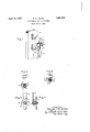
- Fig. 1 shows my invention in perspective; Figs. 2 and 3 re resent difierent ositions of the contacts; ig. 4 is a view of t e finger carrying the bridging contacts and Fig. 5 is a cross section of Fig. 4.
- a base mounted upon a base are the stationary contacts 11 and 12.
- a movable member 13 has attached thereto the arm 14 which supports the moving bridging member or finger 15 carrying the bridging contacts.
- 'Fastened means of the screw 17 is the stub or supportmg member 16 upon which the moving finger 15 is slidably mounted.
- the spring 18 biases the movin finger 15 to the end of the stub member an agamst the por I tion 19 thereof away from the arm 14.
- the finger 15 is provided with the U-shaped projection 21 at one side thereof. This rojection cooperates with the projection 22 i ormed on the arm '14. The action of the contacts during engagement is described below.
- Fig. 2 represents the stationary contact and the movable contact before engagement of the bridgin member with the stationary contacts.
- t e contacts on the movable finger 15 move into engagement with the stationary contacts 11 and 12, the flat surfaces of the contacts enga e with each other. Itis at this moment't at the large rush of current-e passes through the contacts and if there is any tendency-for the metalto melt, this action will take place at this time.
- the projection 21 engages the pro ection 22 and tilts the finger 15, as shown in ig. 3, placing the spring 18 under compression. This tilting action breaks any slight weld that may have taken place when the contacts were temporarily placed in a slightly plastic state.- When the switch is opened the contacts easilIy pass out of engagement with each other.
- a switching mechanism comprising stationary contacts, a bridging member cooperating with said contacts comprising a resiliently mounted bridging element carrying contacts, a projection on said element and means cooperating with said projection for tilting said last contacts laterally with respect to said stationary contacts after enafter engagement of said movable and stationary contacts.
- stationary contacts a movable contact carrying member cooperating therewith and comprisin an arm, a stub thereon, a contact carrying nger slidably mounted on said stub and biased toward the end of said stub away from said arm, a projection on said finger at one side thereof and a projection on said arm coo erating therewith for causing tilting of sald finger on said stub when said contact carrying member moves into engagement with said stationary contacts.
- a switching mechanism comprising stationary contacts, a bridging member provided with contacts for cooperating therewith, a projection on said bridging member, means cooperating with said projection on said bridging member for causing a lateral rocking of said contacts carried thereby after contact with said stationary contacts to prevent freezing.
- a switching mechanism comprising a pair of stationary contacts, amovable member carr ing a resiliently mounted element provide with contacts for cooperating there'- With to bridge said stationary contacts, a projection on said element, means cooperating with said projection to tilt said element and contacts laterally after engagement with said stationary contacts.
- a switching mechanism comprising stationary contacts, a movable member provided with a stub thereon, a finger slidably mounted thereon and carrying contacts for cooperating with said stationary contacts and provided with a projection at one side thereof, a projection on said movable member cooperating with said first projection to tilt said finger on said stub when said contacts are in engagement and a biasing means for holding said finger in an untilted position when sald contacts are out of engagement.
- a switching mechanism comprising a pair of stationary contacts, a movable member provided with a'stub, a finger provided with contacts for bridging said stationary contacts and slidably mounted on said stub, a spring on said stub for biasing said finger to one end of said stub, a projection on said finger at one side thereof, a second projection on said movable member cooperatin therewith for tilting said finger on said stufi
Landscapes
- Slide Switches (AREA)
Description
April 12, 1932. B. w. JONES ANTIFREEZING TIP FOR STARTERS Filed June 6, 1930 Fig. 5.
s e w m m fi ,w tw k u .7 .l .5 Z m Tm.a n v e m B them. This most frequent Patented Apr. 12, 1932 UNITED STATES PATENT OFFICE BENJAMIN WJI'OITES, OI SGHENECTADY, NEW YORK, ASSIGNOB TO GENERAL ELECTRIC 'OOHPANY, A CORPORATION OF NEW YORK mmnnnznae 'rrr ron s'rmrnns Application filed June a, 1930. Serial Io. 459,514.
My invention relates to switches of the bridging contact type and has for its ob ect the provision of a device of this character in which'the contacts will not stick or freeze to etherunder the heaviest service.
n the operation of electromagnetic switches, especially as used in the control of electric motors where the switches are operated .very frequently and the currents are heavy, it occasionally happens that the are formed between the contactsfuses the metal and causes the contacts to stick together due to the formation of a slight weld between y happens where the magnetizin winding is only instantaneousl energize so as to cause the contacts to touc forced into firm engagement. It also sometimes happens because of the small opening of the contacts due to very slow decrease of magnetic pull and other causes. In the type of contact for electromagnetic switches now well lmown in which the contacts slide or roll upon each other so as to produce a W1 ing action, any slight welding or sticking Wlll be overcome by the wiping action if the contact is once wiped home.
In certain types of starters employing the electroma etic switch particularly in small starters w ere it is desirable to obtam a double break for the are so as to obtain a good interruption with a small and simple conemployed which are br1dg struction, two stationary fincgers per phase are e by a movingfinr. This bridging motlon has the desired ouble break but is subject to the objection of freezing due to the fact that sliding or rolling of the contacts is difiicult to obtain I during the operation of the contacts, and would not be particularly desirable since it causesexcessive wear. g
It is, therefore, the principal object of my invention to provide a movable member of the character above described in which freezinglpf the contacts will not take place.
the preferred embodiment of my invention, I provide the moving fin er which carries the bridging contacts wit a projection at one side thereof. This projection cooperates with a second projection which causes a each other without being actuallyto the arm 14 by cause the metal which may have melted is still soft and easy to break and freezing is eliminated.
In the drawings, Fig. 1 shows my invention in perspective; Figs. 2 and 3 re resent difierent ositions of the contacts; ig. 4 is a view of t e finger carrying the bridging contacts and Fig. 5 is a cross section of Fig. 4.
Referring to Figs. 1, 4 and 5, it will be seen that mounted upon a base are the stationary contacts 11 and 12. A movable member 13 has attached thereto the arm 14 which supports the moving bridging member or finger 15 carrying the bridging contacts. 'Fastened means of the screw 17 is the stub or supportmg member 16 upon which the moving finger 15 is slidably mounted. The spring 18 biases the movin finger 15 to the end of the stub member an agamst the por I tion 19 thereof away from the arm 14. The finger 15 is provided with the U-shaped projection 21 at one side thereof. This rojection cooperates with the projection 22 i ormed on the arm '14. The action of the contacts during engagement is described below.
' Fig. 2 represents the stationary contact and the movable contact before engagement of the bridgin member with the stationary contacts. As t e contacts on the movable finger 15 move into engagement with the stationary contacts 11 and 12, the flat surfaces of the contacts enga e with each other. Itis at this moment't at the large rush of current-e passes through the contacts and if there is any tendency-for the metalto melt, this action will take place at this time. Asthe the contacts into closer engagement, the projection 21 engages the pro ection 22 and tilts the finger 15, as shown in ig. 3, placing the spring 18 under compression. This tilting action breaks any slight weld that may have taken place when the contacts were temporarily placed in a slightly plastic state.- When the switch is opened the contacts easilIy pass out of engagement with each other. t
" arm 14 continues to move further in, forcing will thus be seen that I have provided a positive means for preventing freezing of the contacts during operation of the switch.
The embodiment of the invention illustrated and described herein has been selected for the purpose of clearly setting forth the principles involved. It will be apparent, however, that the invention is susceptible of being modified to meet different conditions encountered in its use and I, therefore, aim to cover by the appended claims all modifications within the true spirit of my invention.
What I claim as new and desire to secure by Letters Patent of the United States, is
1. A switching mechanismcomprising stationary contacts, a bridging member cooperating with said contacts comprising a resiliently mounted bridging element carrying contacts, a projection on said element and means cooperating with said projection for tilting said last contacts laterally with respect to said stationary contacts after enafter engagement of said movable and stationary contacts.
6. In a switching mechanism, stationary contacts, a movable contact carrying member cooperating therewith and comprisin an arm, a stub thereon, a contact carrying nger slidably mounted on said stub and biased toward the end of said stub away from said arm, a projection on said finger at one side thereof and a projection on said arm coo erating therewith for causing tilting of sald finger on said stub when said contact carrying member moves into engagement with said stationary contacts.
In witness whereof, I have hereto set my hand this 5th day of June, 1930.
BENJAMIN W. JONES.
gagement with said stationary contacts to prevent freezing.
2. A switching mechanism comprising stationary contacts, a bridging member provided with contacts for cooperating therewith, a projection on said bridging member, means cooperating with said projection on said bridging member for causing a lateral rocking of said contacts carried thereby after contact with said stationary contacts to prevent freezing. I
3. A switching mechanism comprising a pair of stationary contacts, amovable member carr ing a resiliently mounted element provide with contacts for cooperating there'- With to bridge said stationary contacts, a projection on said element, means cooperating with said projection to tilt said element and contacts laterally after engagement with said stationary contacts.
4. A switching mechanism comprising stationary contacts, a movable member provided with a stub thereon, a finger slidably mounted thereon and carrying contacts for cooperating with said stationary contacts and provided with a projection at one side thereof, a projection on said movable member cooperating with said first projection to tilt said finger on said stub when said contacts are in engagement and a biasing means for holding said finger in an untilted position when sald contacts are out of engagement.
5. A switching mechanism comprising a pair of stationary contacts, a movable member provided with a'stub, a finger provided with contacts for bridging said stationary contacts and slidably mounted on said stub, a spring on said stub for biasing said finger to one end of said stub, a projection on said finger at one side thereof, a second projection on said movable member cooperatin therewith for tilting said finger on said stufi
Priority Applications (2)
| Application Number | Priority Date | Filing Date | Title |
|---|---|---|---|
| US459514A US1854039A (en) | 1930-06-06 | 1930-06-06 | Antifreezing tip for starters |
| GB16323/31A GB380057A (en) | 1930-06-06 | 1931-06-04 | Improvements in and relating to electric switches |
Applications Claiming Priority (1)
| Application Number | Priority Date | Filing Date | Title |
|---|---|---|---|
| US459514A US1854039A (en) | 1930-06-06 | 1930-06-06 | Antifreezing tip for starters |
Publications (1)
| Publication Number | Publication Date |
|---|---|
| US1854039A true US1854039A (en) | 1932-04-12 |
Family
ID=23825099
Family Applications (1)
| Application Number | Title | Priority Date | Filing Date |
|---|---|---|---|
| US459514A Expired - Lifetime US1854039A (en) | 1930-06-06 | 1930-06-06 | Antifreezing tip for starters |
Country Status (2)
| Country | Link |
|---|---|
| US (1) | US1854039A (en) |
| GB (1) | GB380057A (en) |
Cited By (6)
| Publication number | Priority date | Publication date | Assignee | Title |
|---|---|---|---|---|
| US2424308A (en) * | 1942-09-15 | 1947-07-22 | Westinghouse Electric Corp | Contactor |
| US2585824A (en) * | 1948-01-27 | 1952-02-12 | Electric Controller & Mfg Co | Electric switch |
| US2625630A (en) * | 1949-01-10 | 1953-01-13 | Emerson Electric Mfg Co | Switch |
| US2761923A (en) * | 1951-04-20 | 1956-09-04 | Bendix Aviat Corp | Electrical switch |
| US2859312A (en) * | 1956-03-15 | 1958-11-04 | Wilcolator Co | Electric switch mechanism |
| US4357509A (en) * | 1979-09-18 | 1982-11-02 | Asea Aktiebolag | Electric switch |
Families Citing this family (1)
| Publication number | Priority date | Publication date | Assignee | Title |
|---|---|---|---|---|
| US3035134A (en) * | 1957-03-21 | 1962-05-15 | Cutler Hammer Inc | Electric switches |
-
1930
- 1930-06-06 US US459514A patent/US1854039A/en not_active Expired - Lifetime
-
1931
- 1931-06-04 GB GB16323/31A patent/GB380057A/en not_active Expired
Cited By (6)
| Publication number | Priority date | Publication date | Assignee | Title |
|---|---|---|---|---|
| US2424308A (en) * | 1942-09-15 | 1947-07-22 | Westinghouse Electric Corp | Contactor |
| US2585824A (en) * | 1948-01-27 | 1952-02-12 | Electric Controller & Mfg Co | Electric switch |
| US2625630A (en) * | 1949-01-10 | 1953-01-13 | Emerson Electric Mfg Co | Switch |
| US2761923A (en) * | 1951-04-20 | 1956-09-04 | Bendix Aviat Corp | Electrical switch |
| US2859312A (en) * | 1956-03-15 | 1958-11-04 | Wilcolator Co | Electric switch mechanism |
| US4357509A (en) * | 1979-09-18 | 1982-11-02 | Asea Aktiebolag | Electric switch |
Also Published As
| Publication number | Publication date |
|---|---|
| GB380057A (en) | 1932-09-05 |
Similar Documents
| Publication | Publication Date | Title |
|---|---|---|
| US2390344A (en) | Electric switch | |
| US2203555A (en) | Electric switch | |
| US1854039A (en) | Antifreezing tip for starters | |
| US2439069A (en) | Delayed-action switch | |
| US2150012A (en) | Circuit breaker | |
| US3953697A (en) | Dual fulcrum switch | |
| US2361162A (en) | Circuit interrupter | |
| US2356521A (en) | Switch structure | |
| US1726233A (en) | Motor-starting switch | |
| US3320392A (en) | Electric control device with improved contact structure | |
| US2402173A (en) | Relay switch | |
| US2399462A (en) | Electric switch | |
| US2596893A (en) | Electric switch | |
| US2323476A (en) | Arc interrupting device | |
| US2449109A (en) | Quick action switch | |
| US2844674A (en) | Snap switch | |
| US1357726A (en) | Electric switch | |
| US2257793A (en) | Circuit breaker | |
| US1231412A (en) | Electromagnetic switch. | |
| US1664845A (en) | Switching device | |
| US3662311A (en) | Thermostat with double pole switch | |
| US2270727A (en) | Electrical contact | |
| US1986222A (en) | Electric switch | |
| US1166339A (en) | Electromagnetic switch. | |
| US2454451A (en) | Electromagnetic switch |