US185402A - Improvement in stuffing-boxes - Google Patents
Improvement in stuffing-boxes Download PDFInfo
- Publication number
- US185402A US185402A US185402DA US185402A US 185402 A US185402 A US 185402A US 185402D A US185402D A US 185402DA US 185402 A US185402 A US 185402A
- Authority
- US
- United States
- Prior art keywords
- stuffing
- rod
- box
- thimble
- compressor
- Prior art date
- Legal status (The legal status is an assumption and is not a legal conclusion. Google has not performed a legal analysis and makes no representation as to the accuracy of the status listed.)
- Expired - Lifetime
Links
- 210000004907 gland Anatomy 0.000 description 3
- 238000012856 packing Methods 0.000 description 3
- 238000010276 construction Methods 0.000 description 1
- 239000000463 material Substances 0.000 description 1
- 238000013022 venting Methods 0.000 description 1
- 239000002699 waste material Substances 0.000 description 1
Images
Classifications
-
- F—MECHANICAL ENGINEERING; LIGHTING; HEATING; WEAPONS; BLASTING
- F16—ENGINEERING ELEMENTS AND UNITS; GENERAL MEASURES FOR PRODUCING AND MAINTAINING EFFECTIVE FUNCTIONING OF MACHINES OR INSTALLATIONS; THERMAL INSULATION IN GENERAL
- F16J—PISTONS; CYLINDERS; SEALINGS
- F16J15/00—Sealings
- F16J15/16—Sealings between relatively-moving surfaces
- F16J15/32—Sealings between relatively-moving surfaces with elastic sealings, e.g. O-rings
Definitions
- This invention relates to a stuffing-box; and the object of the same is to supply the rod working therein with a continuous application of oil to prevent friction, also to prevent the escape of gas around the rod from a compressor to which the stuffing-box is attached.
- the construction of the box and the opera tion of the same are as follows:
- the stuffingbox referred to is intended to be used in connection with an air and gas compressor, to prevent the escape of the air or gas which, in consequence of its attenuation, makes its way through the stuffing-box usually employed for making tight the rod of the pump used in connection therewith.
- An air-compressor is not shown, as it forms no part of the invention, and which invention can be readily understood without showing a compressor or any part thereof.
- the outer section of the box consists of a shell, A, having an interior chamber, B, Fig. 2, whereinis fitted a perforated thimble, O. Exteriorly the middle part of the thimble is cut away, forming an annular recess, 0, between the collars D D, as will be seen in Fig. 4, which represents a detached view of the thimble.
- Said collars when the thimble is in the shell, fit closely to the wall thereof, whereas the recess G forms, in connection with the wall, an annular chamber, E, Fig. 4. Both ends of the thimble are incavated, forming a dishlike or flaring mouth, F, at each end around the bore G.
- the practical operation of the stuffing-box is as follows:
- the space B, Fig. 2, around the rod a is to be filled with packing-matting, such as is ordinarily used for that purpose; or it may be filled with other suitable packing material.
- packing-matting such as is ordinarily used for that purpose; or it may be filled with other suitable packing material.
- the thimble may fit closely in the shell A it should be ground therein, or otherwise fitted so as to secure a close joint.
- an ordinary gland secured by standing bolts, in the ordinary way.
- K in Fig. 1, indicates a flange, whereby the compressor and the stuffingbox are connected to each other; or the shell of the stuffing box may form an integral part of the compressor, being cast in connection therewith.
- the box can be used with or withforated thimble O, annular chambers O and out oil for other rods than that of an air" or "H,'substantial1y in the manner as described,
Landscapes
- Engineering & Computer Science (AREA)
- General Engineering & Computer Science (AREA)
- Mechanical Engineering (AREA)
- Earth Drilling (AREA)
Description
' F. M. McMILLAN.
STUFFING-BOX.
No.185,4OZ.
IIIIJ FRANCIS M. MGMILLAN, OF QLEVELAND, OHIO.
IMPROVEMENT IN sru-FFme eoxas.
Specification forming part of Letters Patent No. 185,402, dated December 19, 1876; application filed July 28, 1876.
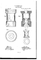
To all whom it may concern Be it known that I, F. M. MOMILLAN, of Cleveland, in the county of Ouyahoga and State of Ohio, have invented new and useful Improvements in Stuffing-Boxes, of which the following is a description, reference being had to the accompanying drawings, making a part of this specification, in which- Figure l is a side view of the stuffing-box. Fig. 2 is a transverse vertical section. Fig. 3 is an end view. Fig. 4 is a detached section.
Like letters of reference refer to like parts in the several views herewith presented.
This invention relates to a stuffing-box; and the object of the same is to supply the rod working therein with a continuous application of oil to prevent friction, also to prevent the escape of gas around the rod from a compressor to which the stuffing-box is attached.
The construction of the box and the opera tion of the same are as follows: The stuffingbox referred to is intended to be used in connection with an air and gas compressor, to prevent the escape of the air or gas which, in consequence of its attenuation, makes its way through the stuffing-box usually employed for making tight the rod of the pump used in connection therewith. An air-compressor is not shown, as it forms no part of the invention, and which invention can be readily understood without showing a compressor or any part thereof.
The outer section of the box consists of a shell, A, having an interior chamber, B, Fig. 2, whereinis fitted a perforated thimble, O. Exteriorly the middle part of the thimble is cut away, forming an annular recess, 0, between the collars D D, as will be seen in Fig. 4, which represents a detached view of the thimble. Said collars, when the thimble is in the shell, fit closely to the wall thereof, whereas the recess G forms, in connection with the wall, an annular chamber, E, Fig. 4. Both ends of the thimble are incavated, forming a dishlike or flaring mouth, F, at each end around the bore G. Interiorly the wall of the thimble is cut away, forming a wide recess therein, which, when the rod (indicated by the dotted lines a, Fig. 2) is passed through the box, forms, in connection therewith, an annular chamber, H, similar to the chamber E, above described.
The practical operation of the stuffing-box is as follows: The space B, Fig. 2, around the rod a is to be filled with packing-matting, such as is ordinarily used for that purpose; or it may be filled with other suitable packing material. In order that the thimble may fit closely in the shell A it should be ground therein, or otherwise fitted so as to secure a close joint. In the lower end I of the shell is fitted an ordinary gland, secured by standing bolts, in the ordinary way.
Between the lower end of the thimble and the end of the gland may be placed some suitable packing. To the opening J is attached the tube of an oil-reservoir, whereby oil is conducted into the annular chamber E, from whence it flows through the perforations b into the annular chamber H, immediately surrounding the rod a.
It will be obvious that by means of the two chambers the rod is in direct contact with the oil, moving through it and in it, as the rod works reciprocally in the stuffing-box, thereby keeping it continuously lubricated; also, in view of the body of oil immediately around and in contact with the rod, the air or gas used in an upright compressor, to which the stuffing-box is attached, cannot escape from the compressor around the rod, the gas or air being unable to pass through the body of oil, nor can it escape through the supply-opening J; hence no waste of gas by leakage occurs around the rod, which in all cases takes place when the rod is packed in the ordinary way, and a common stuffing-box used for the rod.
It will be proper to say here that the compressor is connected directly to the upper end of the box, the rod passing at once into it. K, in Fig. 1, indicates a flange, whereby the compressor and the stuffingbox are connected to each other; or the shell of the stuffing box may form an integral part of the compressor, being cast in connection therewith.
In giving the peculiar curve 0, Fig. 2, to the ends of the thimble, the packing used therewith 011 screwing up the gland, tends to crowd around the rod, and at the same time press outward to the wall of the shell, thereby prehowever; cannot occur when oil is used in the venting leakage around the rod and at the inletJ, substantially as described, and for the sides of the shell A. Such leakage of gas purpose specified.
2. In combination with the shell A, the perchambers. The box can be used with or withforated thimble O, annular chambers O and out oil for other rods than that of an air" or "H,'substantial1y in the manner as described,
gas compressor having a reciprocating moveand for the purpose specified. ment.
7 I FRANCIS -MARION MOMILLAN.
1. The thimble G, having perforations b Witnesses: and curved ends a, annular chambers H and J. H. BUBRIDGE,
O, in combination with piston-rod a and oil- S. SPRINGER.
Publications (1)
| Publication Number | Publication Date |
|---|---|
| US185402A true US185402A (en) | 1876-12-19 |
Family
ID=2254808
Family Applications (1)
| Application Number | Title | Priority Date | Filing Date |
|---|---|---|---|
| US185402D Expired - Lifetime US185402A (en) | Improvement in stuffing-boxes |
Country Status (1)
| Country | Link |
|---|---|
| US (1) | US185402A (en) |
Cited By (1)
| Publication number | Priority date | Publication date | Assignee | Title |
|---|---|---|---|---|
| US20200018397A1 (en) * | 2018-07-11 | 2020-01-16 | Cameron International Corporation | Rolling annular seal |
-
0
- US US185402D patent/US185402A/en not_active Expired - Lifetime
Cited By (2)
| Publication number | Priority date | Publication date | Assignee | Title |
|---|---|---|---|---|
| US20200018397A1 (en) * | 2018-07-11 | 2020-01-16 | Cameron International Corporation | Rolling annular seal |
| US10683934B2 (en) * | 2018-07-11 | 2020-06-16 | Cameron International Corporation | Rolling annular seal |
Similar Documents
| Publication | Publication Date | Title |
|---|---|---|
| US580049A (en) | Apparatus for sealing | |
| US528773A (en) | ellis | |
| US185402A (en) | Improvement in stuffing-boxes | |
| US198391A (en) | Improvement in lubricating-pistons | |
| US216038A (en) | Improvement in piston-rod packings | |
| US909479A (en) | Compound stuffing-box for rods, stems, and shafts. | |
| US572053A (en) | Piston-rod packing | |
| US205120A (en) | Improvement in ammonia or ether machines | |
| US889740A (en) | Stuffing-box. | |
| US778635A (en) | Rod-packing. | |
| US194696A (en) | Improvement in stuffing-boxes for steam-engines | |
| US128906A (en) | Improvement in stuffing-boxes for piston-rods | |
| US267653A (en) | Gas-pump | |
| US745908A (en) | Piston-rod packing. | |
| US1530812A (en) | Piston-rod moisture swab | |
| US712966A (en) | Stuffing-box for steam-engines. | |
| US635334A (en) | Device for oiling piston-rods. | |
| US776900A (en) | Lubricator. | |
| US123097A (en) | Improvement in stuffing-boxes | |
| US1074259A (en) | Stuffing-box. | |
| US163796A (en) | Improvement in stuffing-boxes | |
| US355155A (en) | Egbert fleming | |
| US1211166A (en) | Liquid-sealing box. | |
| US232106A (en) | Feed bold | |
| US302529A (en) | Half to geobge w |