US1853989A - Sink cabinet - Google Patents
Sink cabinet Download PDFInfo
- Publication number
- US1853989A US1853989A US566109A US56610931A US1853989A US 1853989 A US1853989 A US 1853989A US 566109 A US566109 A US 566109A US 56610931 A US56610931 A US 56610931A US 1853989 A US1853989 A US 1853989A
- Authority
- US
- United States
- Prior art keywords
- sink
- cabinet
- front wall
- rod
- slidable
- Prior art date
- Legal status (The legal status is an assumption and is not a legal conclusion. Google has not performed a legal analysis and makes no representation as to the accuracy of the status listed.)
- Expired - Lifetime
Links
Images
Classifications
-
- A—HUMAN NECESSITIES
- A47—FURNITURE; DOMESTIC ARTICLES OR APPLIANCES; COFFEE MILLS; SPICE MILLS; SUCTION CLEANERS IN GENERAL
- A47K—SANITARY EQUIPMENT; ACCESSORIES THEREFOR, e.g. TOILET ACCESSORIES
- A47K1/00—Wash-stands; Appurtenances therefor
- A47K1/02—Portable toilet tables; Wash cabinets or stands
-
- A—HUMAN NECESSITIES
- A47—FURNITURE; DOMESTIC ARTICLES OR APPLIANCES; COFFEE MILLS; SPICE MILLS; SUCTION CLEANERS IN GENERAL
- A47B—TABLES; DESKS; OFFICE FURNITURE; CABINETS; DRAWERS; GENERAL DETAILS OF FURNITURE
- A47B2220/00—General furniture construction, e.g. fittings
- A47B2220/03—Combined cabinets and wash basins
Definitions
- This invention relates generally to cabinets and comprehends a construction prin ariliyi intended to be built beneath a kitchen or bat room sink'.
- Another object of the invention resides in the provision of a novel construction of means for attaching the cabinet to the sink and supporting the same fixed relatively thereto without requiring the use of separable fastening elements for this purpose.
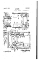
- Figure 7 is a fragmentary perspective view of the upper portion of the cabinet.
- Figure 8 is a similar view of one of the side I walls.
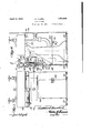
- the cabinet essentially embodies front and P side walls adapted to be arranged in the space between the sink and floor of the room, and if desired these walls may be provided with feet 10 of any suitable construction to prevent v the floor from being marred.
- the front wall is indicatedat 11, while each side wall in cludes 'a fixed section 12 and a relatively slidable section '13. This construction the side walls to be extended when desired or necessary with different size sinks.
- v cured to the upper edge of the front wall 11 and each fixed section 12 of the side walls is a vertically adjustable strip 14,,and each strip is provided with vertically disposed slots 15 through which a suitable fastening element 16 is assed to secure the articular strip to its jacent wall.
- Mani estly are vertically adjustable to'vary the heig t of the cabinet as the occasion may require with sinks spaced different distances above thefloor, gage the lower edge of the sink indicated at 17 Carried by the side walls but secured to the inner faces there of are vertically adjustable strips 18, each having vertically disposed slots 19 to accom modate suitable fastenin elements 20 and these strips 18 are also a a d to be ad'ustr ed for the same purpose as the strips 14 a ve mentioned.
- each fixed section 12 of the side walls Secured to the uppen edge of each fixed section 12 of the side walls is the flange 21 of an angle-shaped bar, the depending flange 22 ofwhich'is arranged in spaced parallel relation to the section 12, and constitutes a guide for the adjacent slidable section 13.
- the res ive sections of each side wall overlap, an that each guide is cut away at its forward end as at 23, to provide a clearance 'for the adjustable plate 18 of the and these strips are adapted to enthese stri '00 slidable sections13 of the slidable section so that the plates 18 of these 8 sections can be elevated to engage the lower edge of the sink.
- the cabinet is also provided with a drawer 24 which slides through an opening in the front wall 11, and supported by a pair of spaced angle brackets 25 clearly illustrated in Figure 6 and each including an attaching ortion 26 secured to the front wall by-suitable fastening elements 27
- the cabinet also includes shelves 28 which are hingedly mounted on the front wall as at 29 and extend along the side walls and repose on suitable brackets 30. These shelves can be elevated to the position illustrated in Figure 2, when the slidable sections 13 ofthe side walls are collapsed to reduce the size of the cabinet for storage or shipping purposes.
- This means may be employed for clamping the cabinet to the cabinet can be quickly and conveniently associatedtherewithwithoutrequirin theuse of separable fastening elements, or etached from the sink as the occasion may require.
- This means preferably includes a pair of vertically disposed rods 31 which slide through spaced brackets 32 and 33 respectively.
- the upper, end of each rod carries a buffer of some suitable material indicated at 34 and adapted to effectively engage the under side of the sink whenthe rod 31 is elevated to its active position as shown in Figure 3.
- Surrounding each .rod is a coil spring 35, one end of which bears against a cross pin 36 carried by the rod, while the opposite end bears against a collar 37 slidable on said rod and provided with a manipulating handle 38.
- each rod Secured to the front Wall adjacent each rod is a bracket 39 having an angularly disposed flange formed with spaced notches 40 to receive the handle 38 of the collar and thereby hold the latter in a given adjusted position with the spring com ressed.
- the collar 37 can be manipulated to elevate the rod 31 until the latter strikes the under side of the sink, and subsequently move in the proper direction to compress the spring 35 after which the handle 38 of the collar is arranged in one of the notches of the stationary bracket 39.
- the cabinet is efl'ectively clamped to the sink and held fixed relatively thereto,
- a front wall of the cabinet is also provided with a door 41 which is normally held in its closed self to what is herein position by a suitable latch 42.
- a sink cabinet adapted to occupy the space between a sink and floor, and comprising a front wall, side walls, each side wall including a fixed section carried by the front wall and a relatively slidable section, shelves supported within the cabinet, a drawer slidable through an opening in the front wall, and means carried by the cabinet for engaging the under side of the sink to support the cabinet fixed relatively thereto in a position for use.
- a sink cabinet adapted to occupy the space between a sink the sink 17, so that description the nature and advantages of 'theinvention will be and floor, and comprising a front wall, side walls, each side wall including a fixed section carried by the front 3.
- a sink cabinet adapted to occupy the space between a sink and floor, and comprising a front wall, side walls, each side wall including a fixed section carried by the front wall and a relatively slidable section, vertically adjustable strips supported by said walls to engage the sink, angle-she ed guides supported on the upper ed es 0 the fixed sections of the side walls or guiding the movement of said slidable sections, each guide bein cut away at one end to provide a clearance or the adjustable stri of the adjacent slidable section, when said section is extended, shelves within the cabinet, means for supportin said shelves and means carried by the ca inet for engaging the sink to hold the cabinet fixed relatlvely thereto in a position for use.
- a sink cabinet adapted to occupy the space between a sink and floor, and comprising a front wall, side walls, vertically ad ustable strips carried by said Walls and adapted to engage the lower edge of the sink, shelves within the cabinet, means for supporting said shelves, vertically disposed rods slidably supported on the front wall, a buffer carried by the up er end of each rod to en age the under side 0 the sink to hold the cablnet fixed relatively thereto in a position for use, and means cooperating with said rods to hold the latter in their elevated active positions.
- a sink cabinet adapted to occupy the space between a sink and floor, and comprising a front wall, side walls, a air of spaced superimposed brackets carrie wall, 1 a vertical] disposed rod slidable through said brac ets, a buffer supported by the upper end of the rod, a collar slidable on said rod and equipped with a handle, a coil spring surrounding the rod and connected with the latter and said collar, whereby adjustment of the latter in one direction will elevate the rod and move said bufler into contacting engagement with the under side of the sink and compress said spring, means copperating with said handle to hold the collar I bythe front 1n a given adjusted position and the rod in
Landscapes
- Health & Medical Sciences (AREA)
- Public Health (AREA)
- Combinations Of Kitchen Furniture (AREA)
Description
April 12, 1932. G NUEBEL' 1,853,989
SINK CABINET Fi1ed Sept. 30, 1951 2 Sheets-Sheet 2 m m T) m INVENTOR m 6 ATTORNEY eazwwiz zez Patented Apr. 12, 1932' OI HEW You sinxcnanmr Application fled September 80,'1981. 8e1 'ial Io. 500,109.
This inventionrelates generally to cabinets and comprehends a construction prin ariliyi intended to be built beneath a kitchen or bat room sink'.
In carrying out the invention I contemplate a cabinet structure for use in'theabove mentioned capacity, and capable of being ad 'usted to accommodate itself to sinks of varymg size and those spaced different distances above the floor.
v Another object of the invention resides in the provision of a novel construction of means for attaching the cabinet to the sink and supporting the same fixed relatively thereto without requiring the use of separable fastening elements for this purpose.
The nature and advantages of the invention will be better understood when the following detail description is read in connection with the accompanying drawings, the invention residing in the construction, combination and arrangement of parts as claimed.
In the drawings forming part of this application like numerals of reference indicate similar parts in the several views and wheresectional view there- 66 of Fig- I ure 4.
Figure 7 is a fragmentary perspective view of the upper portion of the cabinet.
Figure 8 is a similar view of one of the side I walls.
The cabinet essentially embodies front and P side walls adapted to be arranged in the space between the sink and floor of the room, and if desired these walls may be provided with feet 10 of any suitable construction to prevent v the floor from being marred. The front wall is indicatedat 11, while each side wall in cludes 'a fixed section 12 and a relatively slidable section '13. This construction the side walls to be extended when desired or necessary with different size sinks. v cured to the upper edge of the front wall 11 and each fixed section 12 of the side walls is a vertically adjustable strip 14,,and each strip is provided with vertically disposed slots 15 through which a suitable fastening element 16 is assed to secure the articular strip to its jacent wall. Mani estly are vertically adjustable to'vary the heig t of the cabinet as the occasion may require with sinks spaced different distances above thefloor, gage the lower edge of the sink indicated at 17 Carried by the side walls but secured to the inner faces there of are vertically adjustable strips 18, each having vertically disposed slots 19 to accom modate suitable fastenin elements 20 and these strips 18 are also a a d to be ad'ustr ed for the same purpose as the strips 14 a ve mentioned.
Secured to the uppen edge of each fixed section 12 of the side walls is the flange 21 of an angle-shaped bar, the depending flange 22 ofwhich'is arranged in spaced parallel relation to the section 12, and constitutes a guide for the adjacent slidable section 13. It will be noted that the res ive sections of each side wall overlap, an that each guide is cut away at its forward end as at 23, to provide a clearance 'for the adjustable plate 18 of the and these strips are adapted to enthese stri '00 slidable sections13 of the slidable section so that the plates 18 of these 8 sections can be elevated to engage the lower edge of the sink.
The cabinet is also provided with a drawer 24 which slides through an opening in the front wall 11, and supported by a pair of spaced angle brackets 25 clearly illustrated in Figure 6 and each including an attaching ortion 26 secured to the front wall by-suitable fastening elements 27 The cabinet also includes shelves 28 which are hingedly mounted on the front wall as at 29 and extend along the side walls and repose on suitable brackets 30. These shelves can be elevated to the position illustrated in Figure 2, when the slidable sections 13 ofthe side walls are collapsed to reduce the size of the cabinet for storage or shipping purposes.
' y suitable means may be employed for clamping the cabinet to the cabinet can be quickly and conveniently associatedtherewithwithoutrequirin theuse of separable fastening elements, or etached from the sink as the occasion may require. This means preferably includes a pair of vertically disposed rods 31 which slide through spaced brackets 32 and 33 respectively. The upper, end of each rod carries a buffer of some suitable material indicated at 34 and adapted to effectively engage the under side of the sink whenthe rod 31 is elevated to its active position as shown in Figure 3. Surrounding each .rod is a coil spring 35, one end of which bears against a cross pin 36 carried by the rod, while the opposite end bears against a collar 37 slidable on said rod and provided with a manipulating handle 38. Secured to the front Wall adjacent each rod is a bracket 39 having an angularly disposed flange formed with spaced notches 40 to receive the handle 38 of the collar and thereby hold the latter in a given adjusted position with the spring com ressed. By virtue of this construction it 1s obvious that the collar 37 can be manipulated to elevate the rod 31 until the latter strikes the under side of the sink, and subsequently move in the proper direction to compress the spring 35 after which the handle 38 of the collar is arranged in one of the notches of the stationary bracket 39. When the parts are in this position the cabinet is efl'ectively clamped to the sink and held fixed relatively thereto,
but can be quickly separated therefrom by lowering the collar 35 and allowing the rod 31 to gravitate to an inactive position. The
a front wall of the cabinet is also provided with a door 41 which is normally held in its closed self to what is herein position by a suitable latch 42.
While it is believed that from the foregoing readily apparent, I dethat I do not limit myillustrated or described and that such changes may be resorted to when desired as fall within the scope of what sire to have it known is claimed.
What is claimed is:
1. A sink cabinet adapted to occupy the space between a sink and floor, and comprising a front wall, side walls, each side wall including a fixed section carried by the front wall and a relatively slidable section, shelves supported within the cabinet, a drawer slidable through an opening in the front wall, and means carried by the cabinet for engaging the under side of the sink to support the cabinet fixed relatively thereto in a position for use. b
2. A sink cabinet adapted to occupy the space between a sink the sink 17, so that description the nature and advantages of 'theinvention will be and floor, and comprising a front wall, side walls, each side wall including a fixed section carried by the front 3. A sink cabinet adapted to occupy the space between a sink and floor, and comprising a front wall, side walls, each side wall including a fixed section carried by the front wall and a relatively slidable section, vertically adjustable strips supported by said walls to engage the sink, angle-she ed guides supported on the upper ed es 0 the fixed sections of the side walls or guiding the movement of said slidable sections, each guide bein cut away at one end to provide a clearance or the adjustable stri of the adjacent slidable section, when said section is extended, shelves within the cabinet, means for supportin said shelves and means carried by the ca inet for engaging the sink to hold the cabinet fixed relatlvely thereto in a position for use.
4. A sink cabinet adapted to occupy the space between a sink and floor, and comprising a front wall, side walls, vertically ad ustable strips carried by said Walls and adapted to engage the lower edge of the sink, shelves within the cabinet, means for supporting said shelves, vertically disposed rods slidably supported on the front wall, a buffer carried by the up er end of each rod to en age the under side 0 the sink to hold the cablnet fixed relatively thereto in a position for use, and means cooperating with said rods to hold the latter in their elevated active positions.
5-. A sink cabinet adapted to occupy the space between a sink and floor, and comprising a front wall, side walls, a air of spaced superimposed brackets carrie wall, 1 a vertical] disposed rod slidable through said brac ets, a buffer supported by the upper end of the rod, a collar slidable on said rod and equipped with a handle, a coil spring surrounding the rod and connected with the latter and said collar, whereby adjustment of the latter in one direction will elevate the rod and move said bufler into contacting engagement with the under side of the sink and compress said spring, means copperating with said handle to hold the collar I bythe front 1n a given adjusted position and the rod in
Priority Applications (1)
| Application Number | Priority Date | Filing Date | Title |
|---|---|---|---|
| US566109A US1853989A (en) | 1931-09-30 | 1931-09-30 | Sink cabinet |
Applications Claiming Priority (1)
| Application Number | Priority Date | Filing Date | Title |
|---|---|---|---|
| US566109A US1853989A (en) | 1931-09-30 | 1931-09-30 | Sink cabinet |
Publications (1)
| Publication Number | Publication Date |
|---|---|
| US1853989A true US1853989A (en) | 1932-04-12 |
Family
ID=24261527
Family Applications (1)
| Application Number | Title | Priority Date | Filing Date |
|---|---|---|---|
| US566109A Expired - Lifetime US1853989A (en) | 1931-09-30 | 1931-09-30 | Sink cabinet |
Country Status (1)
| Country | Link |
|---|---|
| US (1) | US1853989A (en) |
Cited By (9)
| Publication number | Priority date | Publication date | Assignee | Title |
|---|---|---|---|---|
| US2515099A (en) * | 1950-03-24 | 1950-07-11 | Edward Levy | Sink enclosure |
| US2729530A (en) * | 1950-03-25 | 1956-01-03 | Bernard E Mustee | Housing for laundry tub units |
| US3062608A (en) * | 1960-01-05 | 1962-11-06 | Vincent J Magaline | Adjustable sink closure |
| USD539062S1 (en) | 2004-11-18 | 2007-03-27 | Styka Kimberly A | Sliding bathroom sink drawer |
| US7594706B2 (en) | 2005-11-18 | 2009-09-29 | Styka Kimberly A | Adjustable sliding sink drawer |
| US20100237756A1 (en) * | 2009-03-23 | 2010-09-23 | Hal Weinstein | Pedestal vanity |
| US20110145988A1 (en) * | 2009-12-22 | 2011-06-23 | Le Duff Damian J | Combination sink and countertop with a drawer |
| US10334947B1 (en) | 2018-05-21 | 2019-07-02 | Kohler Co. | Sink shelf |
| USD896459S1 (en) | 2018-05-21 | 2020-09-15 | Kohler Co. | Sink shelf |
-
1931
- 1931-09-30 US US566109A patent/US1853989A/en not_active Expired - Lifetime
Cited By (10)
| Publication number | Priority date | Publication date | Assignee | Title |
|---|---|---|---|---|
| US2515099A (en) * | 1950-03-24 | 1950-07-11 | Edward Levy | Sink enclosure |
| US2729530A (en) * | 1950-03-25 | 1956-01-03 | Bernard E Mustee | Housing for laundry tub units |
| US3062608A (en) * | 1960-01-05 | 1962-11-06 | Vincent J Magaline | Adjustable sink closure |
| USD539062S1 (en) | 2004-11-18 | 2007-03-27 | Styka Kimberly A | Sliding bathroom sink drawer |
| US7594706B2 (en) | 2005-11-18 | 2009-09-29 | Styka Kimberly A | Adjustable sliding sink drawer |
| US20100237756A1 (en) * | 2009-03-23 | 2010-09-23 | Hal Weinstein | Pedestal vanity |
| US20110145988A1 (en) * | 2009-12-22 | 2011-06-23 | Le Duff Damian J | Combination sink and countertop with a drawer |
| US9032566B2 (en) * | 2009-12-22 | 2015-05-19 | Rsi Home Products Management, Inc. | Combination sink and countertop with a drawer |
| US10334947B1 (en) | 2018-05-21 | 2019-07-02 | Kohler Co. | Sink shelf |
| USD896459S1 (en) | 2018-05-21 | 2020-09-15 | Kohler Co. | Sink shelf |
Similar Documents
| Publication | Publication Date | Title |
|---|---|---|
| US1997432A (en) | Shelf construction | |
| US1853989A (en) | Sink cabinet | |
| US3136386A (en) | Foldaway steps | |
| US2893805A (en) | Drawer-type refrigerator device | |
| US3485544A (en) | Hidden storage shelf | |
| US2098198A (en) | Sliding shelf | |
| US3119643A (en) | Laboratory cabinet | |
| US870805A (en) | Ironer's cabinet. | |
| US2337159A (en) | Cabinet | |
| US2126513A (en) | Folding towel rack | |
| US3253870A (en) | Sewing machine cabinets | |
| US1553821A (en) | Wall furniture | |
| US2468662A (en) | Filing cabinet work shelf | |
| US3240545A (en) | Knock down cabinet | |
| US2130279A (en) | Sliding shelf for refrigerator cabinets | |
| US1997793A (en) | Refrigerating apparatus | |
| US1991951A (en) | Cabinet | |
| US2274263A (en) | File cabinet | |
| US925397A (en) | Folding table. | |
| US2657968A (en) | Drawer slide for cabinets | |
| US2527682A (en) | Panel concealed folding ironing board | |
| EP4154765A1 (en) | A wall cabinet | |
| US2224020A (en) | Typewriter or the like desk or cabinet | |
| US2284225A (en) | Dispensing cabinet | |
| US2130168A (en) | Oven construction |