US185397A - Improvement in seeding-machines - Google Patents
Improvement in seeding-machines Download PDFInfo
- Publication number
- US185397A US185397A US185397DA US185397A US 185397 A US185397 A US 185397A US 185397D A US185397D A US 185397DA US 185397 A US185397 A US 185397A
- Authority
- US
- United States
- Prior art keywords
- box
- seed
- shaft
- frame
- seeding
- Prior art date
- Legal status (The legal status is an assumption and is not a legal conclusion. Google has not performed a legal analysis and makes no representation as to the accuracy of the status listed.)
- Expired - Lifetime
Links
- 241000721671 Ludwigia Species 0.000 description 19
- 238000007599 discharging Methods 0.000 description 3
- 238000010899 nucleation Methods 0.000 description 2
- 239000011435 rock Substances 0.000 description 2
- 238000010276 construction Methods 0.000 description 1
- 230000000694 effects Effects 0.000 description 1
Images
Classifications
-
- A—HUMAN NECESSITIES
- A01—AGRICULTURE; FORESTRY; ANIMAL HUSBANDRY; HUNTING; TRAPPING; FISHING
- A01C—PLANTING; SOWING; FERTILISING
- A01C7/00—Sowing
- A01C7/04—Single-grain seeders with or without suction devices
Definitions
- the object of my invention is to provide a seeding attachment which may be applied to a carriage-frame used also for other purposes.
- the invention consists in ,hinging the seedbox to supporting arms or plates, which are fastened to the carrying-frame in such a manner that the seed-box may be adjusted and held at different heights, or entirely detached from the frame at pleasure. It also consists in arranging the driving-shaft upon the seedbox, and placing the driver in such a position upon the box that he can rock it back and forth by simply changing his position thereon, and thus throw'the driving-wheels into and out of gear at pleasure.
- A represents the main or carrying frame, which is supported on two wheels, B B. 'A detailed description of the frame is not necessary here.
- Either thills O or a pole may be attached to the frame A, and the seed-box D is mounted upon the crossbeam a of the carrying-frame.
- Metallic plates or arms b are attached to the upper side of the cross-bar a by screws or in any other manner which Will render them easily detachable.
- Corresponding plates c c are fastened to the bottom of the seed-box D, and the two sets of plates b and c are constructed so as to be pivoted together in pairsat their forward ends, so as to form a kind of strap-hinge.
- the seed-box is fastened to the carrying-frame, and at the same time being hinged thereto may be adjusted so as to throw the driving-shaft into and out of gear, as hereafter described.
- the middle plate c on the seed -box is extended rearward beyond the box, as shown in Fig 2 of the drawings, and to the cross-bar a is pivoted a lever, E.
- This lever is provided with a series of notches, e, Which receive the projecting end of the middle plate c', and so hold the seed-box in any position to which it may be adjusted.
- a shaft, F is supported in bearings f f, attached to the seed-box.
- This shaft carries upon one or both ends a gearwheel, G, which meshes with a gear-wheel, H, attached to the carrying-Wheel B, and thus motion is communicated in the usual manner tothe shaft F, and from it, by any ordinary means, to the usual devices for discharging the seed from the seed-box.
- the bearings of the shaft F on the seed-box are-located in front of the hinges, by which the box is attached to the carrying-frame, so that as the seed-box is vibrated on its hinges the shaft will be raised and lowered, and the range of this motion is sufficient to throw the Wheel G out of and into gear with the wheel H, for the purpose of stopping and starting the scattering mechanism.
- the box is so nearly balanced on its hinges that it maybe rocked sufficiently to effect the necessary adjustment ofthe shaft by the driver sitting onthe box, leaning backward or forward, and the shaft is held in the position desired by the plate c engaging with one of the notches in the lever E.
- the seed-box is protected by a cover, d, which is hinged thereto, and surmounted by a seat, I, for the driver.
- the lever E should be attached to the frame vby a screw or otherwise, so that it may be I claim as new,a.nd desire to secure by Letters -Patent, is-
- the seed-box D secured to the carryingframe by detachable hinges, in combination with suitable mechanism for holding the box in different positions, so that the box may be adjusted on the frame and held at different heights, or entirely removed therefrom, substantially as described.
Landscapes
- Life Sciences & Earth Sciences (AREA)
- Soil Sciences (AREA)
- Environmental Sciences (AREA)
- Sowing (AREA)
Description
E. E. LEACH.
SEEDING-MACHINE.
`N0.1a5,397. ,ab vPatented nec.1e,1e7e.
llllllllll lll lllllllll!llllll'!lllIlllllll llll Il Il lll THE GRAPHIC CC-NX y lUNITED srArns A'rnn'r OFFICE.
EDWIN E. LEAoH, or CEDAR RAPiDs, IOWA.
Specification forming part of Letters Patent No. l5,397, dated December 19, 1876; application filed April 4, 1876.
To all whom it may concern:
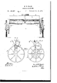
Be it known that I, EDWIN E. LEAoH, of Cedar Rapids, in the county of Linn and State of Iowa, have invented a new and useful Improvement in Seeding-Machines, which is fully described in the following specification, reference being had to the accompanying drawings, in Which- Figure 1 represents a rear elevation of the machine; Fig. 2, a cross-section on the line x 4v, Fig. l; and Fig. 3, an elevation of the gearing end of the machine.
The object of my invention is to provide a seeding attachment which may be applied to a carriage-frame used also for other purposes.
The invention consists in ,hinging the seedbox to supporting arms or plates, which are fastened to the carrying-frame in such a manner that the seed-box may be adjusted and held at different heights, or entirely detached from the frame at pleasure. It also consists in arranging the driving-shaft upon the seedbox, and placing the driver in such a position upon the box that he can rock it back and forth by simply changing his position thereon, and thus throw'the driving-wheels into and out of gear at pleasure.
In the drawings, A represents the main or carrying frame, which is supported on two wheels, B B. 'A detailed description of the frame is not necessary here. Either thills O or a pole may be attached to the frame A, and the seed-box D is mounted upon the crossbeam a of the carrying-frame. p
There is nothing peculiar in the construction of the seed-box. It may be of any style in ordinary use, and should be supplied with the usual fixtures for discharging the seed.
Metallic plates or arms b are attached to the upper side of the cross-bar a by screws or in any other manner which Will render them easily detachable. Corresponding plates c c are fastened to the bottom of the seed-box D, and the two sets of plates b and c are constructed so as to be pivoted together in pairsat their forward ends, so as to form a kind of strap-hinge. By these devices the seed-box is fastened to the carrying-frame, and at the same time being hinged thereto may be adjusted so as to throw the driving-shaft into and out of gear, as hereafter described.
The middle plate c on the seed -box is extended rearward beyond the box, as shown in Fig 2 of the drawings, and to the cross-bar a is pivoted a lever, E. This lever is provided with a series of notches, e, Which receive the projecting end of the middle plate c', and so hold the seed-box in any position to which it may be adjusted. A shaft, F, is supported in bearings f f, attached to the seed-box. This shaft carries upon one or both ends a gearwheel, G, which meshes with a gear-wheel, H, attached to the carrying-Wheel B, and thus motion is communicated in the usual manner tothe shaft F, and from it, by any ordinary means, to the usual devices for discharging the seed from the seed-box. The bearings of the shaft F on the seed-box are-located in front of the hinges, by which the box is attached to the carrying-frame, so that as the seed-box is vibrated on its hinges the shaft will be raised and lowered, and the range of this motion is sufficient to throw the Wheel G out of and into gear with the wheel H, for the purpose of stopping and starting the scattering mechanism.
The box is so nearly balanced on its hinges that it maybe rocked sufficiently to effect the necessary adjustment ofthe shaft by the driver sitting onthe box, leaning backward or forward, and the shaft is held in the position desired by the plate c engaging with one of the notches in the lever E.
It is evident that these devices may be so arranged that the shaft may be attached to the rear of the seed-box, and accomplish the same result, provided the discharging mechanism can be operated by the shaft in this position.
The seed-box is protected by a cover, d, which is hinged thereto, and surmounted by a seat, I, for the driver.
The lever E should be attached to the frame vby a screw or otherwise, so that it may be I claim as new,a.nd desire to secure by Letters -Patent, is-
l. The seed-box D, secured to the carryingframe by detachable hinges, in combination with suitable mechanism for holding the box in different positions, so that the box may be adjusted on the frame and held at different heights, or entirely removed therefrom, substantially as described.
2. The combination of the hinged seed-box carryingr the drive-shaft, mounted and arranged thereon, as described, and a drivers seat on the box, so that the driver, on his seat, can rock the seed-box, and stop and start the seeding mechanism by simply changing his position, substantially as set forth.
`3. The combination of the seed -box D, hinged tothe carrying frame, the projecting plate c', and the notched lever E, substantially as and for the purpose set forth.
EDWIN E. LEACH.
Witnesses:
A. L. ADAMS, H. A. ADAMS.
Publications (1)
| Publication Number | Publication Date |
|---|---|
| US185397A true US185397A (en) | 1876-12-19 |
Family
ID=2254803
Family Applications (1)
| Application Number | Title | Priority Date | Filing Date |
|---|---|---|---|
| US185397D Expired - Lifetime US185397A (en) | Improvement in seeding-machines |
Country Status (1)
| Country | Link |
|---|---|
| US (1) | US185397A (en) |
Cited By (1)
| Publication number | Priority date | Publication date | Assignee | Title |
|---|---|---|---|---|
| US2595461A (en) * | 1946-11-22 | 1952-05-06 | Int Harvester Co | Speed change gearing for grain drills |
-
0
- US US185397D patent/US185397A/en not_active Expired - Lifetime
Cited By (1)
| Publication number | Priority date | Publication date | Assignee | Title |
|---|---|---|---|---|
| US2595461A (en) * | 1946-11-22 | 1952-05-06 | Int Harvester Co | Speed change gearing for grain drills |
Similar Documents
| Publication | Publication Date | Title |
|---|---|---|
| US185397A (en) | Improvement in seeding-machines | |
| US304830A (en) | Grain-drill | |
| US1023752A (en) | Combined fertilizer-distributer and cotton-seed planter. | |
| US341108A (en) | Cultivating and seeding machine | |
| US721306A (en) | Planting attachment for cultivators. | |
| US1074749A (en) | Combined planter and fertilizer-distributer. | |
| US527364A (en) | Grain-drill | |
| US186979A (en) | Improvement in combined cultivator and seeder | |
| US239799A (en) | Combined seed-planter and cultivator | |
| US188942A (en) | Improvement in self-dropping corn-planters | |
| US499856A (en) | Combined planter and distributer | |
| US105000A (en) | Jobdan riggsbee | |
| US347499A (en) | Corn-planter | |
| US204488A (en) | Improvement in combined drill and planter | |
| US151652A (en) | Improvement in seed-sowers and fertilizer-distributers | |
| US327950A (en) | jones | |
| US390722A (en) | Planter | |
| US461153A (en) | Seed planter | |
| US112093A (en) | Improvement in grain-drills | |
| US413211A (en) | Seed-planter | |
| US609666A (en) | Planter | |
| US351047A (en) | Grain-drill | |
| US366964A (en) | Planter | |
| US468178A (en) | Seed-planter | |
| US549805A (en) | Davis l |