US1853972A - Refining hydrocarbons - Google Patents
Refining hydrocarbons Download PDFInfo
- Publication number
- US1853972A US1853972A US128008A US12800826A US1853972A US 1853972 A US1853972 A US 1853972A US 128008 A US128008 A US 128008A US 12800826 A US12800826 A US 12800826A US 1853972 A US1853972 A US 1853972A
- Authority
- US
- United States
- Prior art keywords
- vapor
- treating material
- pipe
- condensate
- treated
- Prior art date
- Legal status (The legal status is an assumption and is not a legal conclusion. Google has not performed a legal analysis and makes no representation as to the accuracy of the status listed.)
- Expired - Lifetime
Links
- 238000007670 refining Methods 0.000 title description 17
- 150000002430 hydrocarbons Chemical class 0.000 title description 8
- 229930195733 hydrocarbon Natural products 0.000 title description 7
- 239000000463 material Substances 0.000 description 81
- 229920000642 polymer Polymers 0.000 description 16
- 230000000379 polymerizing effect Effects 0.000 description 16
- 238000000034 method Methods 0.000 description 13
- 230000005855 radiation Effects 0.000 description 13
- 150000001875 compounds Chemical class 0.000 description 12
- 239000003209 petroleum derivative Substances 0.000 description 12
- 239000007787 solid Substances 0.000 description 12
- 229930195735 unsaturated hydrocarbon Natural products 0.000 description 7
- 239000007788 liquid Substances 0.000 description 6
- 239000012808 vapor phase Substances 0.000 description 6
- 238000010992 reflux Methods 0.000 description 5
- 238000009835 boiling Methods 0.000 description 4
- 238000009833 condensation Methods 0.000 description 4
- 230000005494 condensation Effects 0.000 description 4
- 239000003208 petroleum Substances 0.000 description 3
- 239000003463 adsorbent Substances 0.000 description 2
- 239000003795 chemical substances by application Substances 0.000 description 2
- 238000004891 communication Methods 0.000 description 2
- 238000005336 cracking Methods 0.000 description 2
- 229910000286 fullers earth Inorganic materials 0.000 description 2
- 230000001105 regulatory effect Effects 0.000 description 2
- 150000003464 sulfur compounds Chemical class 0.000 description 2
- 229910001570 bauxite Inorganic materials 0.000 description 1
- 230000003197 catalytic effect Effects 0.000 description 1
- 238000004821 distillation Methods 0.000 description 1
- 239000000446 fuel Substances 0.000 description 1
- 238000010438 heat treatment Methods 0.000 description 1
- 229910000765 intermetallic Inorganic materials 0.000 description 1
- 239000002184 metal Substances 0.000 description 1
- 239000011490 mineral wool Substances 0.000 description 1
- 238000012986 modification Methods 0.000 description 1
- 230000004048 modification Effects 0.000 description 1
- 238000006116 polymerization reaction Methods 0.000 description 1
- 229930195734 saturated hydrocarbon Natural products 0.000 description 1
- 238000012216 screening Methods 0.000 description 1
- 239000000126 substance Substances 0.000 description 1
Images
Classifications
-
- C—CHEMISTRY; METALLURGY
- C10—PETROLEUM, GAS OR COKE INDUSTRIES; TECHNICAL GASES CONTAINING CARBON MONOXIDE; FUELS; LUBRICANTS; PEAT
- C10G—CRACKING HYDROCARBON OILS; PRODUCTION OF LIQUID HYDROCARBON MIXTURES, e.g. BY DESTRUCTIVE HYDROGENATION, OLIGOMERISATION, POLYMERISATION; RECOVERY OF HYDROCARBON OILS FROM OIL-SHALE, OIL-SAND, OR GASES; REFINING MIXTURES MAINLY CONSISTING OF HYDROCARBONS; REFORMING OF NAPHTHA; MINERAL WAXES
- C10G50/00—Production of liquid hydrocarbon mixtures from lower carbon number hydrocarbons, e.g. by oligomerisation
Definitions
- This invention relates to the refining of ing material and minimizes radiation losses hydrocarbons and more especlally' to the refining of cracked distillate by the polymerization and removal of unstable hydrocarbons which renderthem unsuitable for use as motor fuel.
- An object of the invention is to derive heat from the treated vapor to maintain the temperature of the treating material substans tially the same as that of the vapor to be treated.
- the treating material is contained'within a chamber surrounded by an annular space.
- the vapor to an be treated is introduced into the chamber and caused to contact with the treating'material thereby polymerizing the'unstable unsaturated hydrocarbons in the vapor.
- the polymers thus formed are drained from the treating material and collected together with the condensate resulting from the condensation in thetreating material of anyof the vapor.
- the polymers and'condensate may be refluxed into the system for redistilla- 4 tion.
- the treated vapor is then conducted into the annular chamber and circulated about the container, thereby establishing a heat exchange relationship between the vapor and the treating material.
- the vapor 45 acts as an insulating blanket around the treatso that the treating material is maintained substantially at the temperature of the vapor being treated. Some of the treated vapor is condensed in the annular chamber and because of the fact that the undesirable hydrocarbons have been polymerized and removed prior to its condensation, the' condensate may be conducted directly to the condenser in which the vapor issuing from the annular chamber is condensed.
- Figure 2 discloses a modified form of apparatus.
- the still is connected through a pipe 12 controlled by a valve 13 with a fractionator 14 which is of any suitable type and capable of producing the desired fraction which may be gasoline of definite boiling ran e.
- a pipe 15 controlled y the valve 16 leads to a treating tower 17.
- This -tower comprises an inner and an outer shell arranged to form acentral chamber and an annular surrounding chamber.
- Within the central chamber is provided a funnel-shaped perforated shelf 18 terminating in a discharge spout 19 leadingthrough the bottom of the treating tower and controlled by a valve 20.
- Below the shelf 18 there is provided an aperture 21in the inner shell of the tower 17 through which communication is established between the inner and outer chamber.
- the pipe 16 extends through the annular chamber and communicates only with the cen-' tral chamber at'a point above the shelf 18. A.
- a reflux pipe 29 leads from the fractionator 14 to the supply line 11 for the still 10.
- a reflux pipe 31 leads from the central chamber of the tower 17 to the pipe 29.
- a trapped pipe 32 controlled by valve 33 leads from the bottom of the annular chamber of the tower 17 to the .pipe 22 at a point ahead of the valve 23.
- a pipe 34 controlled by a valve 35 leads from the pipe 32 at a point ahead of the valve 33 to a storage tank 36.
- a pipe 37 controlled by Valve 38 leads from the pipe 32 'at a point ahead of the valve 33 to the reflux pipe 31.
- a pipe 39 controlled by a valve 40 leads from the pipe 31 to the base of the fractionating tower 14 and a valve 41 is provided in the pipe 31 below the pipe 39.
- any liquid collecting in the bottom of the central chamber of tower 17 may be refluxed either to the fractionator 14 or the still 10. Also by regulation of the valves 33, 35, 38. and 41, any liquid collecting in the annular chamber of tower 17 may be caused to flow as desired into the 30 condenser 24, the tank 36 or the pipe 31 material.
- the valves 13, 16, 23 By means of the valves 13, 16, 23,
- Vapor from the fractionator may be supplied to the treating tower under atmospheric or superatmospheric pressure by proper regulation of the valves.
- 10a is the still to which oil is supplied through pipe 11a.
- a pipe 12a controlled by a valve 13a leads to a fractionator 14a which may be of any suit able type to yield the desired fraction which may be gasoline of definte boiling range.
- a pipe 150 controlled by a valve 16a leads to a treating tower 17a.
- the treating tower comprises an inner and an outer shell dividing the tower into a central and an annular chamber. The upper portion of the inner shell is formed of screening or netting 21a thereby establishing communication between the inner and outer chambers.
- a funnel-shaped perforated shelf 18a terminating in a discharge spout 19a extending through the bottom of the tower and controlled by a valve 20a.
- the pipe 15a extends through the annular cham er and communicates only with the central chamber at a point below the shelf 18a.
- a pipe 22a controlled by a valve 23a communicates with the annular chamber at a point near the bottom thereof and leads to a condenser 24a.
- From the condenser a pipe 25a leads to a storage tank 26a provided with a vent pipe 27a controlled by a valve 2811.
- reflux line 2911 leads from the fractionator 14a through a pump 30a to the supply pipe 11a for the still 10a.
- a reflux line 31a leads from the bottom of the central chamber of the tower 17a to the pipe 29a.
- a pipe 32a controlled by a valve 33a leads from the bottom of the annular chamber of the tower 17 a through a trap to the pipe 22a.
- a pipe 34a controlled by a valve 35a leads from the pipe 32a at a point ahead of the valve 33a to a tank 36a.
- a pipe 37 a controlled by a valve 38a leads from the pipe 32a at a point ahead of the valve 33a to the pipe 31a.
- a pipe 39a controlled by a valve 40a leads from the pipe 31a to the base of the fractionating tower,
- valve 41a is provided in the pipe 310 below the pipe 39a.
- any liquid collecting in the bottom of the central chamber of tower 17a may be refluxed either to the fractionator 14a or the still 1011.
- any liquid collecting in the annular chamber of tower 17a may be caused to flow as desired into the condenser 24a, the tank 36a or the pipe 31a through which it may be refluxed directly to the still 1011 or to the fractionator 14a.
- the pressure in the different parts of the system may be regulated by means of the valves 13a, 16a, 23a and 28a.
- the inner chamber of the treating tower in each apparatus is charged with a material capable of polymerizing the undesirable un-' saturated hydrocarbons present in cracked distillate. This material is prevented from sifting through the perforations in the shelf by means of screens or layers of mineral wool or the like.
- the still 10 is heated and oil to be cracked or a previously cracked distillate is admitted thereto.
- the distillate is supplied to the fractionator from which is discharged the desired fraction which may be gasoline of definite boiling range.
- the vapor from the fractionator is led into the upper art of the central chamber and caused to ow downwardly through the treating material.
- the undesirable unsaturated hydrocarbons are polymerized.
- the polymers thus formed being of higher boiling point than the temperature of the vapor become liquid and drip through the perforations into the bottom of the inner chamber.
- the treated vapors escape through the aperture 21 into the annular chamber and are led up around the inner shell thereby being brought into heat exchange relation with the heating material.
- the treating material is thus maintained at a suflicientlv high temperature to prevent excessive condensation of vapor during the polymerizing operation.
- Some of the vapor is cooled in this operation and cond'erised.
- This condensate is led out through the pipe 32 either to the condenser 24 or storage tank 36 or is refluxed through the pipe 37 for redistillation as desired.
- the polymers together with any condensate that may have been formed in the polymerizing operation may be refluxed into the still or into the fractionator 14.
- Fig. 2 The operation of the apparatus disclosed in Fig. 2 is substantially the same as the apparatus disclosed in Fig. 1. In this apparatus the vapor to be treated flows upwar'dly through the treating material instead of downwardly as in the apparatus of Fig. 1.
- each modification treated vapor is caused to circulate around the container to the treating material at a temperature substantially that of the vapor to be treated.
- each instance the liquid collecting in the annular chamber has been condensed from treated vapor and constitutes part of the desired product. It may, therefore, be taken directly to the condenser and there mixed with the condensate from the vapor discharged from the tower.
- the valves in the vapor line may be adjusted to attain the pressures desired in the different parts of the system so that if desired the vapor to be treated may be brought into contact with the treating material either at atmospheric or super-atmospheric pressure.
- the treating material is thus maintained at an effective temperature without any loss of efliciency in the operation of thesystem after the treating material has once become thoroughly heated.
- the condensate collecting in the annular chamber comes from vapor which has been subjected to the treating material and is therefore a part of the finished product.
- some of the desired product may be condensed in the treating material and collected with the polymers in the lower portion of the annular chamber of the treating tower. This condensate together with the polymers may be refluxed for redistillation.
- Such condensate may at the beginning of the operation be considerable because of the fact that the treating material has not been brought up to temperature but after the treating material has been brought up to temperature, such condensate is comparatively small.
- the treating material where it is desired simply to remove the unstable unsaturated hydrocarbons from the vapors, may be fullers earth, bauxite, or any other adsorbent substance.
- the agent maybe a metal or metallic compound having an aflinity for the sulfur compounds in the vapors, which may be mixed with an adsorbent material.
- the method of refining cracked-petroleum products which comprises passing the same in vapor phase 'and under super-atmospheric pressure through a body of solid treating material capable of polymerizing the unstable, unsaturated hydrocarbons present in said vapor, draining from said body of treating material condensate including polymers formed therein, withdrawing the treated vapor from said body of treating material and passing the same into indirect heat exchange relation therewith to reduce loss of heat from the treating. material by radiation and subsequently condensing the vapor.
- the method of refining cracked petroleum products which comprises passing the same in vapor form through a body of solid treating material capable of polymerizmaterial by radiation and subsequently condensing the treated vapor.
- the method of refining cracked petroleum products which comprises passing the 1 same in vapor form and under super-atmospheric pressure through a body of solid treating material capable of polymerizing the unstable, unsaturated compounds contained in the vapor, draining from said body of treating material condensate comprising polymers formed therein, separating the treated vapor from said condensate, passing said treated vapor into indirect heat exchange relation with said treating material to reduce loss of heat from the treating material by radiation and subsequently condensing the treated vapor.
- the method of refining cracked petroleum products which comprises passing the same in vapor form through a body of solid treating material capable of polymerizing the unstable, unsaturated compounds present in the vapor, draining from said body of treating material condensate comprising polymers formed therein, separately withdrawing the treated vapor from the body of treating material and passing the same into indirect heat exchange relation with said body of treating material to reduce loss of heat from the treating material by radiation, collecting condensate resulting from the heat exchange operation, condensing the treated vapor and adding thereto the condensate resulting from the heat exchange eration.
- the method of refining crac ed petroleum products which comprises passing the same in vapor form and under super-atmospheric pressure through a body of solid treating material capable of polymerizing the unstable, unsaturated compounds present in the vapor, draining from said body of treating material condensate comprising polymers formed therein, separately withdrawing the treated vapor from the body of treating material and passing the same into indirect heat exchange relation with said body of treat ing material to reduce loss of heat from the treating material by radiation, collecting condensate resulting from the heat exchange operation, condensing the 7 treated vapor and adding thereto the condensate resulting from the heat exchange operation.
- the method of refining cracked petroleum products which comprises passing the same in vapor form and under super-atmospheric pressure through a body of solid treating material capable of polymerizing the unstable unsaturated compounds contained in the vapor, draining from, the body of treating material condensate including polymers formed therein, separately withdrawing the Y treated vapor from the body of treating material and passing the same into indirect heat the petroleum to cracking conditions, passwithdrawing the treated vapor from the treating material and passing the same into indirect heat exchange relation with the treating material to reduce loss of heat from the treating material by radiation and subsequently condensing the treated vapor.
- the method of refining cracked petroleum products whichcomprises passing the same in vapor phase through a body of solid treating material capable of polymerizing the unstable, unsaturated hydrocarbons present in the vapor, draining from said body of treating material condensate comprising polymers formed therein, separating the treated vapor from said condensate, passing said treated vapor around said body of treating material in heat exchange relation therewith to reduce loss of heat from said treating material by radiation and subsequently condensing the treated vapor.
- the method of refining petroleum products containing unstable, unsaturated compounds which consists in passing such products in vapor phase through a body of solid treating material capable of polymerizing said unstable, unsaturated compounds, withdrawing from the body of treating material condensate comprising polymers formed therein, withdrawing treated vapor from said treating material and passing the same around the treating material in indirect heat exchange relation therewith to reduce loss of heat from said treating material by radiation, condensing the treated vapor and adding thereto the condensate resulting from the heat exchange operation.
- the method of refining petroleum products containing unstable unsaturated compounds which consists in passing the same in vapor phase and under superatmospheric pressure through a body of solid treating material capable of polymerizing said unstable, unsaturated compounds, draining from said body of treating material condensate includingpolymers formed therein, withdrawing the treatedvapor from said body of treating material and passing the same around the treating material in indirect heat exchange relation therewith to reduce loss of heat from said treating material by radiation and subsequently condensing the vapors.
- the method of refining petroleum products containing unstable, unsaturated compounds which consists in passing the same in vapor phase and under super-atmospheric pressure through a body of solid treating material capable of polymerizing said unstable, unsaturated compounds, draining from said body of treating material condensate including polymers formed therein, withdrawing the treated vapor from said body of treating material and passing the same around the treating material in indirect heat exchange relation therewith to reduce loss of heat from said treating material by radiation, condensing the treated Vapor and adding 7 thereto the condensate resulting from the 10 heat exchange operation.
Landscapes
- Chemical & Material Sciences (AREA)
- Oil, Petroleum & Natural Gas (AREA)
- Engineering & Computer Science (AREA)
- Chemical Kinetics & Catalysis (AREA)
- General Chemical & Material Sciences (AREA)
- Organic Chemistry (AREA)
- Production Of Liquid Hydrocarbon Mixture For Refining Petroleum (AREA)
Description
T. T. GRAY 1,853,972
REFINING HYDROCARBONS April 12, 1932.
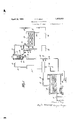
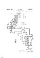
2 Sheets-Sheet 1 Filed Aug. 9, 1926 a vwentoz April 12, 1932. GRAY REFINING' HYDROCARBONS Filed Aug. 9, 1926 2 Sheets-Sheet 2 gnvemtoz W f $313M abtovnMg/a W Patented Apr. 12, 1932 v UNITED STATES PATENT OFFICE THOMAS '1. GRAY, F ELIZABETH, NEW JERSEY, ASSIGN'OR TO THE GRAY PROCESSES CORPORATIQN, OF NEWARK, NEW JERSEY, A CORPORATION OF DELAWARE L REFINING HYDROCARBONS Application filed August 9, 1926. Serial No.y128,008.
This invention relates to the refining of ing material and minimizes radiation losses hydrocarbons and more especlally' to the refining of cracked distillate by the polymerization and removal of unstable hydrocarbons which renderthem unsuitable for use as motor fuel.-
Cracked petroleum distillates contain unstable unsaturated hydrocarbons which are polymerized on standing thereby impairing m the quality of gasolene. In applicants Patent No. 1,340,889 there is disclosed a process for polymerizing and removing the undesirable hydrocarbon compounds of cracked distillate which consists in bringing the cracked distillate in vapor form into contact with a catalytic agent such for example as fullers earth. To prevent excessive loss of the desired product by condensation of vapor in the treating material, the latter is best maintained substantially at the temperature of the vapors.
An object of the invention is to derive heat from the treated vapor to maintain the temperature of the treating material substans tially the same as that of the vapor to be treated.
.According to the invention the treating material is contained'within a chamber surrounded by an annular space. The vapor to an be treated is introduced into the chamber and caused to contact with the treating'material thereby polymerizing the'unstable unsaturated hydrocarbons in the vapor. The polymers thus formed are drained from the treating material and collected together with the condensate resulting from the condensation in thetreating material of anyof the vapor. The polymers and'condensate may be refluxed into the system for redistilla- 4 tion. The treated vapor is then conducted into the annular chamber and circulated about the container, thereby establishing a heat exchange relationship between the vapor and the treating material. 'The vapor 45 acts as an insulating blanket around the treatso that the treating material is maintained substantially at the temperature of the vapor being treated. Some of the treated vapor is condensed in the annular chamber and because of the fact that the undesirable hydrocarbons have been polymerized and removed prior to its condensation, the' condensate may be conducted directly to the condenser in which the vapor issuing from the annular chamber is condensed.
Other objects, novel features and advantages of the invention will be apparent from the following specification and accompanying drawings wherein Figure 1 discloses one form of apparatus for treating cracked distillates in accordance with the invention, and
Figure 2 discloses a modified form of apparatus.
designates astill of the tube type to which oil to be cracked or a cracked distillate from a previous cracking operation is supplied from a source not vshown through a pipe 11. The still is connected through a pipe 12 controlled by a valve 13 with a fractionator 14 which is of any suitable type and capable of producing the desired fraction which may be gasoline of definite boiling ran e. From the fractionator a pipe 15 controlled y the valve 16 leads to a treating tower 17. This -tower comprises an inner and an outer shell arranged to form acentral chamber and an annular surrounding chamber. Within the central chamber is provided a funnel-shaped perforated shelf 18 terminating in a discharge spout 19 leadingthrough the bottom of the treating tower and controlled by a valve 20. Below the shelf 18 there is provided an aperture 21in the inner shell of the tower 17 through which communication is established between the inner and outer chamber. The pipe 16 extends through the annular chamber and communicates only with the cen-' tral chamber at'a point above the shelf 18. A.
5 26 which is provided with a vent pipe 27 controlled by a valve 28. A reflux pipe 29 leads from the fractionator 14 to the supply line 11 for the still 10. A reflux pipe 31 leads from the central chamber of the tower 17 to the pipe 29. A trapped pipe 32 controlled by valve 33 leads from the bottom of the annular chamber of the tower 17 to the .pipe 22 at a point ahead of the valve 23. A pipe 34 controlled by a valve 35 leads from the pipe 32 at a point ahead of the valve 33 to a storage tank 36. A pipe 37 controlled by Valve 38 leads from the pipe 32 'at a point ahead of the valve 33 to the reflux pipe 31. A pipe 39 controlled by a valve 40 leads from the pipe 31 to the base of the fractionating tower 14 and a valve 41 is provided in the pipe 31 below the pipe 39. By proper manipulation of the valves 40 and 41, any liquid collecting in the bottom of the central chamber of tower 17 may be refluxed either to the fractionator 14 or the still 10. Also by regulation of the valves 33, 35, 38. and 41, any liquid collecting in the annular chamber of tower 17 may be caused to flow as desired into the 30 condenser 24, the tank 36 or the pipe 31 material. By means of the valves 13, 16, 23,
28, the-pressure in different portions of the system may be regulated as desired. Vapor from the fractionator may be supplied to the treating tower under atmospheric or superatmospheric pressure by proper regulation of the valves.
In Fig. 2, 10a is the still to which oil is supplied through pipe 11a. From the still a pipe 12a controlled by a valve 13a leads to a fractionator 14a which may be of any suit able type to yield the desired fraction which may be gasoline of definte boiling range. A pipe 150 controlled by a valve 16a leads to a treating tower 17a. The treating tower comprises an inner and an outer shell dividing the tower into a central and an annular chamber. The upper portion of the inner shell is formed of screening or netting 21a thereby establishing communication between the inner and outer chambers. Within the inner shell is provided a funnel-shaped perforated shelf 18a terminating in a discharge spout 19a extending through the bottom of the tower and controlled by a valve 20a. The pipe 15a extends through the annular cham er and communicates only with the central chamber at a point below the shelf 18a. A pipe 22a controlled by a valve 23a communicates with the annular chamber at a point near the bottom thereof and leads to a condenser 24a. From the condenser a pipe 25a leads to a storage tank 26a provided with a vent pipe 27a controlled by a valve 2811. A
reflux line 2911 leads from the fractionator 14a through a pump 30a to the supply pipe 11a for the still 10a. A reflux line 31a leads from the bottom of the central chamber of the tower 17a to the pipe 29a. A pipe 32a controlled by a valve 33a leads from the bottom of the annular chamber of the tower 17 a through a trap to the pipe 22a. A pipe 34a controlled by a valve 35a leads from the pipe 32a at a point ahead of the valve 33a to a tank 36a. A pipe 37 a controlled by a valve 38a leads from the pipe 32a at a point ahead of the valve 33a to the pipe 31a. A pipe 39a controlled by a valve 40a leads from the pipe 31a to the base of the fractionating tower,
14a and a valve 41a is provided in the pipe 310 below the pipe 39a. By proper manipulation of the valves 40a and 41a, any liquid collecting in the bottom of the central chamber of tower 17a may be refluxed either to the fractionator 14a or the still 1011. Also by regulation of the valves 33a, 35a, 38a, 40a and 41a, any liquid collecting in the annular chamber of tower 17a may be caused to flow as desired into the condenser 24a, the tank 36a or the pipe 31a through which it may be refluxed directly to the still 1011 or to the fractionator 14a. The pressure in the different parts of the system may be regulated by means of the valves 13a, 16a, 23a and 28a.
The inner chamber of the treating tower in each apparatus is charged with a material capable of polymerizing the undesirable un-' saturated hydrocarbons present in cracked distillate. This material is prevented from sifting through the perforations in the shelf by means of screens or layers of mineral wool or the like.
In the operation of the apparatus disclosed in Fig. 1 the still 10 is heated and oil to be cracked or a previously cracked distillate is admitted thereto. The distillate is supplied to the fractionator from which is discharged the desired fraction which may be gasoline of definite boiling range. The vapor from the fractionator is led into the upper art of the central chamber and caused to ow downwardly through the treating material. During the flow of the vapor through the treating material the undesirable unsaturated hydrocarbons are polymerized. The polymers thus formed being of higher boiling point than the temperature of the vapor become liquid and drip through the perforations into the bottom of the inner chamber. The treated vapors escape through the aperture 21 into the annular chamber and are led up around the inner shell thereby being brought into heat exchange relation with the heating material. The treating material is thus maintained at a suflicientlv high temperature to prevent excessive condensation of vapor during the polymerizing operation. Some of the vapor is cooled in this operation and cond'erised. This condensate is led out through the pipe 32 either to the condenser 24 or storage tank 36 or is refluxed through the pipe 37 for redistillation as desired. The polymers together with any condensate that may have been formed in the polymerizing operation may be refluxed into the still or into the fractionator 14.
The operation of the apparatus disclosed in Fig. 2 is substantially the same as the apparatus disclosed in Fig. 1. In this apparatus the vapor to be treated flows upwar'dly through the treating material instead of downwardly as in the apparatus of Fig. 1.
In each modification treated vapor is caused to circulate around the container to the treating material at a temperature substantially that of the vapor to be treated. In
each instance the liquid collecting in the annular chamber has been condensed from treated vapor and constitutes part of the desired product. It may, therefore, be taken directly to the condenser and there mixed with the condensate from the vapor discharged from the tower. The valves in the vapor line may be adjusted to attain the pressures desired in the different parts of the system so that if desired the vapor to be treated may be brought into contact with the treating material either at atmospheric or super-atmospheric pressure.
The treating material is thus maintained at an effective temperature without any loss of efliciency in the operation of thesystem after the treating material has once become thoroughly heated. The condensate collecting in the annular chamber comes from vapor which has been subjected to the treating material and is therefore a part of the finished product. Of course some of the desired product may be condensed in the treating material and collected with the polymers in the lower portion of the annular chamber of the treating tower. This condensate together with the polymers may be refluxed for redistillation. Such condensate may at the beginning of the operation be considerable because of the fact that the treating material has not been brought up to temperature but after the treating material has been brought up to temperature, such condensate is comparatively small.
The treating material, where it is desired simply to remove the unstable unsaturated hydrocarbons from the vapors, may be fullers earth, bauxite, or any other adsorbent substance. Where it is also desired to remove sulfur compounds the agent maybe a metal or metallic compound having an aflinity for the sulfur compounds in the vapors, which may be mixed with an adsorbent material.
Having thus described my invention, what from petroleum which comprises distilling petroleum under super-atmospheric pressure, passing the vapor of distillation while under supera'tmospheric pressure throu h a body of solid treating material capable oi polymerizing the unstable, unsaturated hydrocarbons present in the vapor, draining from said treating material condensate comprising polymers formed in the treating material, withdrawing the treated vapor from the treating material and passing the same into indirect heat exchange relation'with the treating material to reduce loss of heat from the treating material by radiation and subsequently condensing the vapor.
2. The method of refining petroleum products containing unstable, unsaturated compounds which consists in passing the same in vapor phase through a body of solid treating material capable of polymerizing said unstable, unsaturated compounds, Withdrawing from the body of treating material condensate comprising polymers formed therein, withdrawing treated vapor from said treating material and passing the same into indirect heat exchange relation therewith to reduce loss of heat from the treating material by radiation and subsequently condensing said vapor. v
3. The method of refining cracked-petroleum products which comprises passing the same in vapor phase 'and under super-atmospheric pressure through a body of solid treating material capable of polymerizing the unstable, unsaturated hydrocarbons present in said vapor, draining from said body of treating material condensate including polymers formed therein, withdrawing the treated vapor from said body of treating material and passing the same into indirect heat exchange relation therewith to reduce loss of heat from the treating. material by radiation and subsequently condensing the vapor.
4. The method of refining cracked petroleum products which comprises passing the same in vapor form through a body of solid treating material capable of polymerizmaterial by radiation and subsequently condensing the treated vapor.
5. The method of refining cracked petroleum products which comprises passing the 1 same in vapor form and under super-atmospheric pressure through a body of solid treating material capable of polymerizing the unstable, unsaturated compounds contained in the vapor, draining from said body of treating material condensate comprising polymers formed therein, separating the treated vapor from said condensate, passing said treated vapor into indirect heat exchange relation with said treating material to reduce loss of heat from the treating material by radiation and subsequently condensing the treated vapor.
6. The method of refining cracked petroleum products which comprises passing the same in vapor form through a body of solid treating material capable of polymerizing the unstable, unsaturated compounds present in the vapor, draining from said body of treating material condensate comprising polymers formed therein, separately withdrawing the treated vapor from the body of treating material and passing the same into indirect heat exchange relation with said body of treating material to reduce loss of heat from the treating material by radiation, collecting condensate resulting from the heat exchange operation, condensing the treated vapor and adding thereto the condensate resulting from the heat exchange eration.
7. The method of refining crac ed petroleum products which comprises passing the same in vapor form and under super-atmospheric pressure through a body of solid treating material capable of polymerizing the unstable, unsaturated compounds present in the vapor, draining from said body of treating material condensate comprising polymers formed therein, separately withdrawing the treated vapor from the body of treating material and passing the same into indirect heat exchange relation with said body of treat ing material to reduce loss of heat from the treating material by radiation, collecting condensate resulting from the heat exchange operation, condensing the 7 treated vapor and adding thereto the condensate resulting from the heat exchange operation.
8. The method of refining cracked petroleum products which comprises passing the same in vapor form and under super-atmospheric pressure through a body of solid treating material capable of polymerizing the unstable unsaturated compounds contained in the vapor, draining from, the body of treating material condensate including polymers formed therein, separately withdrawing the Y treated vapor from the body of treating material and passing the same into indirect heat the petroleum to cracking conditions, passwithdrawing the treated vapor from the treating material and passing the same into indirect heat exchange relation with the treating material to reduce loss of heat from the treating material by radiation and subsequently condensing the treated vapor.
10. The method of refining cracked petroleum products whichcomprises passing the same in vapor phase through a body of solid treating material capable of polymerizing the unstable, unsaturated hydrocarbons present in the vapor, draining from said body of treating material condensate comprising polymers formed therein, separating the treated vapor from said condensate, passing said treated vapor around said body of treating material in heat exchange relation therewith to reduce loss of heat from said treating material by radiation and subsequently condensing the treated vapor.
11. The method of refining petroleum products containing unstable, unsaturated compounds which consists in passing such products in vapor phase through a body of solid treating material capable of polymerizing said unstable, unsaturated compounds, withdrawing from the body of treating material condensate comprising polymers formed therein, withdrawing treated vapor from said treating material and passing the same around the treating material in indirect heat exchange relation therewith to reduce loss of heat from said treating material by radiation, condensing the treated vapor and adding thereto the condensate resulting from the heat exchange operation.
12. The method of refining petroleum products containing unstable unsaturated compounds which consists in passing the same in vapor phase and under superatmospheric pressure through a body of solid treating material capable of polymerizing said unstable, unsaturated compounds, draining from said body of treating material condensate includingpolymers formed therein, withdrawing the treatedvapor from said body of treating material and passing the same around the treating material in indirect heat exchange relation therewith to reduce loss of heat from said treating material by radiation and subsequently condensing the vapors.
13. The method of refining petroleum products containing unstable, unsaturated compounds which consists in passing the same in vapor phase and under super-atmospheric pressure through a body of solid treating material capable of polymerizing said unstable, unsaturated compounds, draining from said body of treating material condensate including polymers formed therein, withdrawing the treated vapor from said body of treating material and passing the same around the treating material in indirect heat exchange relation therewith to reduce loss of heat from said treating material by radiation, condensing the treated Vapor and adding 7 thereto the condensate resulting from the 10 heat exchange operation.
In testimony whereof, I have signed my name to this specification THOMAS T. GRAY.
Priority Applications (1)
| Application Number | Priority Date | Filing Date | Title |
|---|---|---|---|
| US128008A US1853972A (en) | 1926-08-09 | 1926-08-09 | Refining hydrocarbons |
Applications Claiming Priority (1)
| Application Number | Priority Date | Filing Date | Title |
|---|---|---|---|
| US128008A US1853972A (en) | 1926-08-09 | 1926-08-09 | Refining hydrocarbons |
Publications (1)
| Publication Number | Publication Date |
|---|---|
| US1853972A true US1853972A (en) | 1932-04-12 |
Family
ID=22433133
Family Applications (1)
| Application Number | Title | Priority Date | Filing Date |
|---|---|---|---|
| US128008A Expired - Lifetime US1853972A (en) | 1926-08-09 | 1926-08-09 | Refining hydrocarbons |
Country Status (1)
| Country | Link |
|---|---|
| US (1) | US1853972A (en) |
-
1926
- 1926-08-09 US US128008A patent/US1853972A/en not_active Expired - Lifetime
Similar Documents
| Publication | Publication Date | Title |
|---|---|---|
| US1853972A (en) | Refining hydrocarbons | |
| US2271097A (en) | Treating hydrocarbon oils | |
| US2077494A (en) | Process of clay treating petroleum distillates | |
| US1839019A (en) | Process for converting petroleum oil | |
| US1843151A (en) | Process of cracking oil | |
| US1770098A (en) | Method of cracking oil | |
| US1664977A (en) | Art of distilling lubricating oils | |
| US1656710A (en) | Refining oils | |
| US2127654A (en) | Process for treating hydrocarbon distillates | |
| US1892452A (en) | Process for cracking hydrocarbon oil | |
| US2112360A (en) | Apparatus for cracking petroleum oil | |
| US1958959A (en) | Treating hydrocarbon oils | |
| US1962752A (en) | Treating hydrocarbon oils | |
| US1901158A (en) | Refining hydrocarbons | |
| US1599777A (en) | Process of treating oil | |
| US1924855A (en) | Treatment of hydrocarbon oils | |
| US1744262A (en) | Process and apparatus for treating petroleum oils | |
| US1891107A (en) | Method of polymerizing hydrocarbon oils | |
| US1878580A (en) | Process of treating cracked hydrocarbons | |
| US2105499A (en) | Method and apparatus for treating cracked hydrocarbon oils | |
| US1698076A (en) | Manufacturing of lubricating oil | |
| US1839388A (en) | Decolorization of lubricating oils | |
| US1902056A (en) | Treating hydrocarbon oils | |
| US1891109A (en) | Oil purifying system | |
| US1853671A (en) | Petroleum refining |