US1853971A - Adjustable cutter - Google Patents
Adjustable cutter Download PDFInfo
- Publication number
- US1853971A US1853971A US330912A US33091229A US1853971A US 1853971 A US1853971 A US 1853971A US 330912 A US330912 A US 330912A US 33091229 A US33091229 A US 33091229A US 1853971 A US1853971 A US 1853971A
- Authority
- US
- United States
- Prior art keywords
- blades
- cutter
- serrations
- clamping
- pair
- Prior art date
- Legal status (The legal status is an assumption and is not a legal conclusion. Google has not performed a legal analysis and makes no representation as to the accuracy of the status listed.)
- Expired - Lifetime
Links
- 238000010276 construction Methods 0.000 description 6
- 101100379079 Emericella variicolor andA gene Proteins 0.000 description 1
- 238000006073 displacement reaction Methods 0.000 description 1
- 230000000694 effects Effects 0.000 description 1
- 230000037431 insertion Effects 0.000 description 1
- 238000003780 insertion Methods 0.000 description 1
- 238000004519 manufacturing process Methods 0.000 description 1
- 239000007787 solid Substances 0.000 description 1
Images
Classifications
-
- B—PERFORMING OPERATIONS; TRANSPORTING
- B23—MACHINE TOOLS; METAL-WORKING NOT OTHERWISE PROVIDED FOR
- B23B—TURNING; BORING
- B23B29/00—Holders for non-rotary cutting tools; Boring bars or boring heads; Accessories for tool holders
- B23B29/03—Boring heads
- B23B29/034—Boring heads with tools moving radially, e.g. for making chamfers or undercuttings
- B23B29/03403—Boring heads with tools moving radially, e.g. for making chamfers or undercuttings radially adjustable before starting manufacturing
- B23B29/03407—Boring heads with tools moving radially, e.g. for making chamfers or undercuttings radially adjustable before starting manufacturing by means of screws and nuts
- B23B29/0341—Cartridges
-
- Y—GENERAL TAGGING OF NEW TECHNOLOGICAL DEVELOPMENTS; GENERAL TAGGING OF CROSS-SECTIONAL TECHNOLOGIES SPANNING OVER SEVERAL SECTIONS OF THE IPC; TECHNICAL SUBJECTS COVERED BY FORMER USPC CROSS-REFERENCE ART COLLECTIONS [XRACs] AND DIGESTS
- Y10—TECHNICAL SUBJECTS COVERED BY FORMER USPC
- Y10T—TECHNICAL SUBJECTS COVERED BY FORMER US CLASSIFICATION
- Y10T408/00—Cutting by use of rotating axially moving tool
- Y10T408/86—Tool-support with means to permit positioning of the Tool relative to support
- Y10T408/885—Tool-support with means to permit positioning of the Tool relative to support including tool-holding clamp and clamp actuator
- Y10T408/888—Movable along tool-axis
Definitions
- the invention relates to adjustable cutters more particularly designed for-use in connection with boring bars-and of the type in which similar cutting edges are formed on diametrically opposite ends of the tool. It is essential with this type of'cutter that the cutting edges should be held in rigid relation to the supporting bar and at exactly the same distance from the axis thereof. It is also necessary to provide for the sharpening. of. the cutting edges while maintaining the same diameter. V Heretofore various constructions of adjust-- able cutter blades have been devised which,
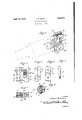
- Figure 1 is a perspective view showing the cutter in full lines in relation to-a boring bar indicated in dotted lines i 1 e a
- Figure 2 is a side elevation of the cutter;
- Figure 3 is an end elevationthereof;
- Figure 4 is an-elevation-from the opposite end";
- Figure 5 is an elevation f'thetapere'd se' curingpin;
- p Figure 6 is a transversesection through a boring bar showing the'cutting toolclamped in rigid relation thereto. 1
- Figure '7 is a vsection'on the line 7 7 of Figure 2. 1 -v 1 g
- a transverse 'slot in which the cutter bar is placed and where a solid bar'- isflusedthis may be securely clamped by a transversely extending tapered pin engaging i929.
- a and A are the cutter blades which are formed ofrectangular bars of exact predetermined dimensions. These bars which are adjacent'to each other. are formed with aseries of transverse serrations or teeth Bjwhioh are preferably finely spaced as for instance about/ one thirty-sec ond of an inch.
- the serrations are very accurately formed, preferably of a V-shape and The faces of I of approximately a60 degree'angle.
- the member C is I also; provided with a serrated face but preferably one in which the serrations areonly one-halfthe width of those between the mem bers A and A. Thus, ifthe latter are spaced one thirty-second of an inch, thespacing ofthe serration s'in the member C'would V V be one sixty-fourth" of an inch.
- Similarser V rations are formed the edges of'the imem-' V r r bers A and berCv I V I V
- adjustmentI have provided first I a clamping screw 'D which engages a At which abut v against the memthreaded aperture'in the member and has i its head engaging a shouldered slot E in the member A.
- This permits the screw D to clamp the blades A and A to each other in whatever adjustment may have been made in their relative positions and when thus clamped to hold the interlocking serrations from d1sengagement,l also provide one or more clamping screws F for securing the member C to the blades.
- screws F are arranged in the centralonineet ing plane of the membersA and A- and engage nuts F which are arranged in registering grooves F in the members A and A. lhe arrangement is such that whenthe members A and A are relatively adjusted the nuts F canslide in the grooves Fflbut when thescrews F are tightened they will clamp the member C to said members A A.
- the member C is provided on its outerface with a notch G which is preferably tapered from oneside to the other and is adapted to engage a tapering pin H. The latter is inserted in an aperture in the boring bar whichextends transversely of the slot for receiving the cutte-r.
- edaend portion H for engaging the correspondingly threaded portion of the aperture and by means of which the pin 'may be drawn inward to efi'ect the clamping .
- the outer endof the pin is provided with a cross slot H for theengagement of a screw driver by which it ,is operated.
- the blades A and A may be adjusted in rela- .tion to each otherso that the cutting edges 0t said blades are an exact distance apart.
- the blades are then clamped in this position of adjustment by the tightening of the screw D. I .nextadjust the clamping blades in relation to the member C so that the spacing between the ⁇ axial plane of the notch G. and the cutting edges ofthe respectiveblades is equal.
- Such adjustment is facilitated by the exactness of the serrations so that it is unnecessary for the; operator to make use of calipers or any other measuring instrument.
- the wholeassembly may be slipped ,in tog the slot in. the boring bar and then clamped by the insertion of thep-in H and the screwing of the same into tight engagement.
- the members are of exact rectangular form they can be made to accurately lit the slot in the boring bar and ac.- justment between the members will not in any way effect the cross sectional size of the asemb y.
- Innsethe tool may be easily and quickly adjusted for any desired diameter of bore and after adjustment may be ground to sharpen the cutting edges in; the usual manner.
- A- cutting tool comprising a pair of blades of oblong rectangular cross .section As shown, these 'l fhe pin is also provided with a thread clamping'said third member with the serrations 111 interlocking engagement with the I pa r oi members, and positlonlng and clamping means engaging said third member for securing the same and the whole assembly in rigid position in relation to the holder.
- the combination with a boring bar having transversely ex ending tool holding slot, of a cutting tool comprising a pair of blades having. serratedengaging faces, a third member ofa widthequal to the combined Width of said blades and having a serrated edge for engaging correspondingly serrated edgesnof said blades, means for clamping said blades to each other-and said-thirdpmember thereto in different positions of adjustment, and a pin engaging said boring bar to.
- third member extendin the direction transverse to said tool holding slot, said pin engaging a notch invsaid; third member and serving to clamp the same and 1ktj ewhole assemblyiin; rigid relation to the A cutting'tool; comprising a holder, a pair of oppositelyextendingblades having adjacentfaces, means for clamping said adjacent faces together in different positions of relative-adjustment, a third imemberadjacent to one edge ofsaidpair of blades, means ifor. adjustably clamping said. third member to; the, pair, and meansfor holding said third member in a predetermined position in said holder to center the blades with respect to the axis of the holder.
- a tool holder reeessec letonreceive a-cutter of a pair. of oppositely extending cutter blades having adjacent faces-means for clamping said blades to each otherin diii'erentpositions of relative adjustment, a third member relatively ad ustable and adjacent to one edge of. the pair ofblades, means independent of said holder for jclampingsaid, third member to said pair of blades in different positions of relative adjustment and means for holding said third member inpredeterminedposition in said holder adapted to hold the entire assembly in fixed relation to said holder and position said-.bladeswith respect to the axis of said holder. 7 c i 5.
- Thecembinatio-n'with atooli holder recessed to receive a cutter, of a cutter assembly comprising a-pair of oppositely extending relatively adjustable blades having trans .versely serrated adjacent faces, meansfor clampingsaid blades with said serrations in nterlocking engagement, a third member ad.-
- a cutting tool comprising a pair of oppositely extending blades having transverse serrations on their adjacent faces permitting of relative adjustment, the cuttingedges of said blades being in the plane of said adjacent faces, clamping means for holding said ser- 1 rations in interlocking engagement, and a 7 width of the serrations in the adjacent faces third member at one edge of the pair transversely serrated for engaging serrations in both members thereof, the serrations in said third member being spaced one-half the of said blades.
Description
April 12, 1932,
J. B. GIERN ADJUSTABLE CUTTER File d Jan. 7, 1929 INVENTOR ATTORNES' v Patented Apr. 12, 1932 sTA TEtS JAMES 'B. GIERN, or nn'rnoir, ivrrcmealv, AssIcNoR 'ronETRoI'r BORING :iaAn co vr- PA Y, F DErRorr, MICHIGAN, A GORP-QRATION or MICHIGAN I a 7 AT NT IC AnJus'rA nE cc'r'rrm Application filed January "7,
The invention relates to adjustable cutters more particularly designed for-use in connection with boring bars-and of the type in which similar cutting edges are formed on diametrically opposite ends of the tool. It is essential with this type of'cutter that the cutting edges should be held in rigid relation to the supporting bar and at exactly the same distance from the axis thereof. It is also necessary to provide for the sharpening. of. the cutting edges while maintaining the same diameter. V Heretofore various constructions of adjust-- able cutter blades have been devised which,
. '15 however, have not been satisfactory in oper ation. The chief difficulty has been to secure the required'rigiditywhile the blade islper-H forming its work so as to obtain the desired accuracies it is obvious that'any slight shift- 29 ing of one cutting edge in relation to-the other or in relation to the axis of the bar will destroy the accuracy of thecut. It is the ob: ject of the present invention to obtaina con struction which whileproviding for adjustment maintains a high degree of rigidity. It is a further object to provide'for fairly minute adjustments with a high degree of accuracy; 'With these objects in view the invention consists in. the construction as herein after set forth. V
In the drawings: 3 u Figure 1 is a perspective view showing the cutter in full lines in relation to-a boring bar indicated in dotted lines i 1 e a Figure 2 is a side elevation of the cutter; Figure 3 is an end elevationthereof; Figure 4: is an-elevation-from the opposite end";'. v I 4 Figure 5 is an elevation f'thetapere'd se' curingpin; p Figure 6 is a transversesection through a boring bar showing the'cutting toolclamped in rigid relation thereto. 1
Figure '7 :is a vsection'on the line 7 7 of Figure 2. 1 -v 1 g In'the manufacture of boring bars it is usual to provide a transverse 'slot in which the cutter bar is placed and where a solid bar'- isflusedthis may be securely clamped by a transversely extending tapered pin engaging i929." Serial m.; a3'o,912,
a correspondingly tapered notch'in theside edge of the-bar. On the other'hand where the cutter is adjustable, it is necessary to provide two blades which must be clamped in relation to each other as well as being clamped to the bar. With my improved construction I employa pair of relatively adjustable cutter blades and a; third member 7 j with respect to which both blades are adjustthe clamping wedge or pin. I have also pro- 7 vided a construction in which these three members when adjusted are locked from any possibility of accidental displacement. This consists in forming on the abutting-faces ,of the blades transversely extendingserrations which willinterlock with each other, Simableu Said third memberdirectly en :1:
ilar serrations'are formed on the edges of the blades which-abut againstthe third member, thereby obtaining a. rigid interlocking engagement between this member and both of the'blades. v
a In detail, A and A, are the cutter blades which are formed ofrectangular bars of exact predetermined dimensions. these bars which are adjacent'to each other. are formed with aseries of transverse serrations or teeth Bjwhioh are preferably finely spaced as for instance about/ one thirty-sec ond of an inch. The serrations are very accurately formed, preferably of a V-shape and The faces of I of approximately a60 degree'angle. O is the clamping or holding member which is a rec tangular bar and is of a width equaljto'the v combined Widthof the bars A andA, When they are placed together: The member C is I also; provided with a serrated face but preferably one in which the serrations areonly one-halfthe width of those between the mem bers A and A. Thus, ifthe latter are spaced one thirty-second of an inch, thespacing ofthe serration s'in the member C'would V V be one sixty-fourth" of an inch. Similarser V rations are formed the edges of'the imem-' V r r bers A and berCv I V I V To hold themembers A513 and C in differ-i ent positionsof,adjustmentI have provided first I a clamping screw 'D which engages a At which abut v against the memthreaded aperture'in the member and has i its head engaging a shouldered slot E in the member A. This permits the screw D to clamp the blades A and A to each other in whatever adjustment may have been made in their relative positions and when thus clamped to hold the interlocking serrations from d1sengagement,l also provide one or more clamping screws F for securing the member C to the blades. screws F are arranged in the centralonineet ing plane of the membersA and A- and engage nuts F which are arranged in registering grooves F in the members A and A. lhe arrangement is such that whenthe members A and A are relatively adjusted the nuts F canslide in the grooves Fflbut when thescrews F are tightened they will clamp the member C to said members A A. The member C is provided on its outerface with a notch G which is preferably tapered from oneside to the other and is adapted to engage a tapering pin H. The latter is inserted in an aperture in the boring bar whichextends transversely of the slot for receiving the cutte-r. edaend portion H for engaging the correspondingly threaded portion of the aperture and by means of which the pin 'may be drawn inward to efi'ect the clamping .The outer endof the pin is provided with a cross slot H for theengagement of a screw driver by which it ,is operated.
Vith, the .construction as described, beforeinserting the cutter into theboring. bar the blades A and A may be adjusted in rela- .tion to each otherso that the cutting edges 0t said blades are an exact distance apart. The blades are then clamped in this position of adjustment by the tightening of the screw D. I .nextadjust the clamping blades in relation to the member C so that the spacing between the} axial plane of the notch G. and the cutting edges ofthe respectiveblades is equal. Such adjustment is facilitated by the exactness of the serrations so that it is unnecessary for the; operator to make use of calipers or any other measuring instrument. .When the member C is properly positioned and clamped by the screws F, the wholeassembly may be slipped ,in tog the slot in. the boring bar and then clamped by the insertion of thep-in H and the screwing of the same into tight engagement. ,As all of the members are of exact rectangular form they can be made to accurately lit the slot in the boring bar and ac.- justment between the members will not in any way effect the cross sectional size of the asemb y.
Innsethe tool may be easily and quickly adjusted for any desired diameter of bore and after adjustment may be ground to sharpen the cutting edges in; the usual manner.
What I claim as myzinvention is:
1. A- cutting tool comprisinga pair of blades of oblong rectangular cross .section As shown, these 'l fhe pin is also provided with a thread clamping'said third member with the serrations 111 interlocking engagement with the I pa r oi members, and positlonlng and clamping means engaging said third member for securing the same and the whole assembly in rigid position in relation to the holder.
The combination with a boring bar having transversely ex ending tool holding slot, of a cutting tool comprising a pair of blades having. serratedengaging faces, a third member ofa widthequal to the combined Width of said blades and having a serrated edge for engaging correspondingly serrated edgesnof said blades, means for clamping said blades to each other-and said-thirdpmember thereto in different positions of adjustment, and a pin engaging said boring bar to. extendin the direction transverse to said tool holding slot, said pin engaging a notch invsaid; third member and serving to clamp the same and 1ktj ewhole assemblyiin; rigid relation to the A cutting'tool; comprising a holder, a pair of oppositelyextendingblades having adjacentfaces, means for clamping said adjacent faces together in different positions of relative-adjustment, a third imemberadjacent to one edge ofsaidpair of blades, means ifor. adjustably clamping said. third member to; the, pair, and meansfor holding said third member in a predetermined position in said holder to center the blades with respect to the axis of the holder.
a. The combinationwith a tool holder reeessec letonreceive a-cutter, of a pair. of oppositely extending cutter blades having adjacent faces-means for clamping said blades to each otherin diii'erentpositions of relative adjustment, a third member relatively ad ustable and adjacent to one edge of. the pair ofblades, means independent of said holder for jclampingsaid, third member to said pair of blades in different positions of relative adjustment and means for holding said third member inpredeterminedposition in said holder adapted to hold the entire assembly in fixed relation to said holder and position said-.bladeswith respect to the axis of said holder. 7 c i 5. Thecembinatio-n'with atooli holder recessed to receive a cutter, of a cutter assembly comprising a-pair of oppositely extending relatively adjustable blades having trans .versely serrated adjacent faces, meansfor clampingsaid blades with said serrations in nterlocking engagement, a third member ad.-
j acent to the pair of blades and having transverse serrations engaging corresponding serrations in said blades, means for locking said third member in said toolholder adapted to hold the entire assembly in rigid relation thereto.
6. A cutting tool comprising a pair of oppositely extending blades having transverse serrations on their adjacent faces permitting of relative adjustment, the cuttingedges of said blades being in the plane of said adjacent faces, clamping means for holding said ser- 1 rations in interlocking engagement, and a 7 width of the serrations in the adjacent faces third member at one edge of the pair transversely serrated for engaging serrations in both members thereof, the serrations in said third member being spaced one-half the of said blades.
In testimony whereof I aflix my signature.
JAMES B. GIER-N.
Priority Applications (1)
| Application Number | Priority Date | Filing Date | Title |
|---|---|---|---|
| US330912A US1853971A (en) | 1929-01-07 | 1929-01-07 | Adjustable cutter |
Applications Claiming Priority (1)
| Application Number | Priority Date | Filing Date | Title |
|---|---|---|---|
| US330912A US1853971A (en) | 1929-01-07 | 1929-01-07 | Adjustable cutter |
Publications (1)
| Publication Number | Publication Date |
|---|---|
| US1853971A true US1853971A (en) | 1932-04-12 |
Family
ID=23291838
Family Applications (1)
| Application Number | Title | Priority Date | Filing Date |
|---|---|---|---|
| US330912A Expired - Lifetime US1853971A (en) | 1929-01-07 | 1929-01-07 | Adjustable cutter |
Country Status (1)
| Country | Link |
|---|---|
| US (1) | US1853971A (en) |
Cited By (4)
| Publication number | Priority date | Publication date | Assignee | Title |
|---|---|---|---|---|
| US2477482A (en) * | 1945-02-22 | 1949-07-26 | Irene J Florin | Floating precision cutter |
| US3327572A (en) * | 1965-11-17 | 1967-06-27 | Futurmill Inc | Tool holder |
| US3455188A (en) * | 1967-09-11 | 1969-07-15 | Donald W Pratt | Adjustable boring cutter |
| US20090169313A1 (en) * | 2007-12-30 | 2009-07-02 | Iscar Ltd. | Cutting Insert and Cutting Tool Therefor |
-
1929
- 1929-01-07 US US330912A patent/US1853971A/en not_active Expired - Lifetime
Cited By (5)
| Publication number | Priority date | Publication date | Assignee | Title |
|---|---|---|---|---|
| US2477482A (en) * | 1945-02-22 | 1949-07-26 | Irene J Florin | Floating precision cutter |
| US3327572A (en) * | 1965-11-17 | 1967-06-27 | Futurmill Inc | Tool holder |
| US3455188A (en) * | 1967-09-11 | 1969-07-15 | Donald W Pratt | Adjustable boring cutter |
| US20090169313A1 (en) * | 2007-12-30 | 2009-07-02 | Iscar Ltd. | Cutting Insert and Cutting Tool Therefor |
| US8696254B2 (en) * | 2007-12-30 | 2014-04-15 | Iscar, Ltd. | Cutting insert and cutting tool therefor |
Similar Documents
| Publication | Publication Date | Title |
|---|---|---|
| US1681675A (en) | Rotary cutter | |
| US2537517A (en) | Metal cutting tool | |
| US1853971A (en) | Adjustable cutter | |
| US2814854A (en) | Milling cutter | |
| US4011025A (en) | Expanding reamer | |
| US4564320A (en) | Form broach assembly | |
| US2385750A (en) | Metal removing tool | |
| US3300834A (en) | Milling cutter tool | |
| US1756986A (en) | Inserted-blade cutter | |
| US2395570A (en) | Cutting tool | |
| US1964130A (en) | Milling and like cutting tool | |
| US3239911A (en) | Bit holder | |
| US3138044A (en) | Combination reamer and pipe deburrer | |
| US1650290A (en) | Milling cutter | |
| US1934465A (en) | Inserted tooth cutter | |
| US2063128A (en) | Bit and tool holder | |
| US4280542A (en) | Cutterhead for a portable power planer | |
| US3273223A (en) | Cutting tools | |
| US1721129A (en) | Adjusting means for threading dies | |
| US715377A (en) | Gage for cutters or tools. | |
| US3142111A (en) | Rotary cutting tools | |
| US1411799A (en) | Milling and like cutting tool | |
| US2185187A (en) | Rotary cutter | |
| US3012450A (en) | Saw filing implement | |
| US2657066A (en) | Tool holding collet for boring bar assemblies |