US1853969A - Circuits for coupling lines of different impedances - Google Patents
Circuits for coupling lines of different impedances Download PDFInfo
- Publication number
- US1853969A US1853969A US351880A US35188029A US1853969A US 1853969 A US1853969 A US 1853969A US 351880 A US351880 A US 351880A US 35188029 A US35188029 A US 35188029A US 1853969 A US1853969 A US 1853969A
- Authority
- US
- United States
- Prior art keywords
- impedance
- circuits
- transformer
- repeater
- circuit
- Prior art date
- Legal status (The legal status is an assumption and is not a legal conclusion. Google has not performed a legal analysis and makes no representation as to the accuracy of the status listed.)
- Expired - Lifetime
Links
- 230000008878 coupling Effects 0.000 title description 8
- 238000010168 coupling process Methods 0.000 title description 8
- 238000005859 coupling reaction Methods 0.000 title description 8
- 230000005540 biological transmission Effects 0.000 description 8
- 230000000694 effects Effects 0.000 description 6
- 238000004804 winding Methods 0.000 description 5
- 230000001627 detrimental effect Effects 0.000 description 3
- 239000004020 conductor Substances 0.000 description 2
- 230000001939 inductive effect Effects 0.000 description 2
- PCLIRWBVOVZTOK-UHFFFAOYSA-M 2-(1-methylpyrrolidin-1-ium-1-yl)ethyl 2-hydroxy-2,2-diphenylacetate;iodide Chemical compound [I-].C=1C=CC=CC=1C(O)(C=1C=CC=CC=1)C(=O)OCC[N+]1(C)CCCC1 PCLIRWBVOVZTOK-UHFFFAOYSA-M 0.000 description 1
- 235000003930 Aegle marmelos Nutrition 0.000 description 1
- 244000058084 Aegle marmelos Species 0.000 description 1
- 239000002131 composite material Substances 0.000 description 1
- 230000004048 modification Effects 0.000 description 1
- 238000012986 modification Methods 0.000 description 1
Images
Classifications
-
- H—ELECTRICITY
- H04—ELECTRIC COMMUNICATION TECHNIQUE
- H04B—TRANSMISSION
- H04B3/00—Line transmission systems
- H04B3/02—Details
- H04B3/04—Control of transmission; Equalising
- H04B3/14—Control of transmission; Equalising characterised by the equalising network used
- H04B3/143—Control of transmission; Equalising characterised by the equalising network used using amplitude-frequency equalisers
Definitions
- Objects of the invention are to increase the efciency of a telephone and telegraph circuit when incidental cable lengths are connected therein; ,toeliminate at voicefrequene cies singingin repeater circuits d ue to 1m'- ped'ance distortion which may be introduced bythe incidental cabl-e sections, and to elimi# nate at carrier frequenciesreiection ,eects tending to producecross talk adj a'cent'cir-J ditonsr are met whichk require sections of un'- loaded cable at various points intermediate to an open wire line.
- the impedancejlooking into one section of the circuit should be theconjugate of that In long telephone andtelegraph lines'cn-l,
- vas .regards resistance,the4 circuits may bev designed for both maximum energy transfer and minimum reflection, as regards reactance, ifl -maximum energy ⁇ transfer* ⁇ is ⁇ desired the reactances of vthe two circuits must be opposite in sign, but if total absence of reflection is desired the reactances must be of the same sign. i In particular cases inetermediate relationships may prove more expedient. e i Y i Y .In the type of circuit to which this inventionhas particular reference, two conditions are encountered depending upon whether the cable section is'near a line repeater or located at a considerable distance therefrom.l When near a repeater the impedance.
- theimpedance looking away from the repeater must simulate the impedance of the repeater vbalancing network.v If this were not the case the unbalance would result in singing, o r acontinuous transfer of energy from one branch ofthe repeater tothe otherlwhich aralyzes the repeater and prevents it from v unctioning properly. ,At the same time equalizing the impedances atv y to a large extent undesirable reflection effectss 'y Another condition exists when the incirfdental cable section is at apoint remote from the repeater. Where the ⁇ line connecting the repeater with the end of the cable section is long, the manner of its terminationvvisof small I consequence since the impedance looking away,
- balancing network same as the balancing network or the same as an open wire line, but may be the conjugate thereof to satisfy the conditions of maximum energy transfer.
- the invention resides in means for properly balancing the repeater hybrid coil, and for t-lie second case where the cable section is remote from the repeater in mea-ns for obtaining maximum energy transfer.
- the invention is based upon the principle that the equivalent circuit of an auto-transformer with a condenser in the bridge arm when reduced to unity ratio basis is a T section having series and shunt elements, the series arms each representing the leakage impedance of the transformer plus the series component of the capacity of the'condenser and the shunt arms the mutual impedance of the transformer plus the shunt component of the capacity of the condenser. Furthermore, at the lower voice frequencies wherethe condenser iii-the bridge arm of the auto-transformer introduces the impedance irregularity, the cable lengthsv are electrically so short that the transformers at each end of the cable maybe regarded as being back to back.
- An equivalent network of the combination comprising the two sections of open wire line, the Vintermediate short section of cable and the auto-transformer and condenser couplings may comprise, therefore, two ofthe unity ratio equivalent circuits described above-connected in tandem and terminated by impedances which equal the characteristic impedance of the open wire line. It is apparent that the transmission and impedance characteristics' of this combination network may be controlled within certain limits at the lower voice frequencies by merely varying the values of the elements representing the mutual inipedances of the transformers, in
- unity ratio mutual impedance may be defined as the shunt impedance of the 'equivalent unity ratio T section of a fixed ratio transformer.
- This unity ratio mutual impedance of the transformer may be controlled in the physical transformer by varyin the values of an inductive element or com ination of inductive elements therein without .changing the transformer impedance ratio at carrier frequencies.
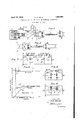
- Figs, 1 and 2 show two different circuit conditions to which the invention is applicable;
- Fig. 3 an exact equivalent network of the transformers and the associated cable length shown in Figs. 1 and 2 at voice frequencies;
- Fig. 4 an approximation of the sameequivalent network;
- Fig. a group of impedance characteristic curves of the circuits of Figs. 1 and 2 under different conditions;
- Fig. 6 a diagrammatic view of a portionlof the circuits of Figs. 1 and 2 when the impedance of the cable sections are neglected as they may be under certain conditions of circuit operation.
- Fig. 1 represents a circuit embodying the invention in which an incidental cable section 1 is connected in aline in close proximity to voice repeating apparatus 2.
- the hybrid coil 3 of the repeater is terminated in a balancing network 4 and is connected to the line in accordance with well-known practice bythe repeating coil 5.
- a composite set 6 and high pass filter circuit 7 are provided for lay-passing the telegraph and carrier currents, respectively, around the voice frequency repeater while the low-pass filter 9 excludes the carrier frequencies from the Voice repeater. ,Since this is the case in which the incidental cable section is in close proximity to the repeater, the leads 10 are necessarily short.
- the cable section 1 is electrically short in the voice frequency range and if this range were all that had to be considered, the impedance of the cable section could be neglected.
- the attenuation of the cable section is sufficiently great to require impedance matching and since each wire of the line is equipped to carry grounded Morse telegraph signals, the matching is accomplished by the use of autotransformerslh and 121 having'the condens"- ers 13 and 14V at; their respective:midpointsi to :properly segregatel the ⁇ grounded telegraph; circuits.
- Transformers of thiisztype' areusu-y Y l allydesigned .tohave a very high mutualaim-l pedance, and when a condenserhaving thev optimum value of: capacity determinedfby telegraph considerations is used the imped'l ance looking into the transformer 11 differ-s' greatly from that of. an. open wirelineat the lower ⁇ voice frequencies.
- Fig. 5 which represents thereactance chan acteristic over the voice range' of van' open" 15* wire line andthe curveB which're resents the characteristic reactance lookingfinto the transformer 11v when the transformers are designed' for* maximum* mutual impedance.
- f Since the balancing network 4 1s commonly ⁇ Vdesigned forthe case where the'repeater is connectedV toan open wireline "the unbalance which 1s introduced between ,theV impedance of this network and theimpeldance looking toward the transformer 11 Vis sufficiently greatto' cause singing ofthe repeater and -rwlien terminated at B-B in the openwire detrimental reflection-effects.
- transformer maybe made tojapproximate closelythatf of ⁇ an open' wire line; in other 'words, the repeater'systemto-the left of the linek B--B is terminated" in the impedance for which ⁇ it,y is-.designed, in. consequence of which. thetendency of the repeater tofsingi may be eliminated., Y
- the impedancey of the cable section 1 may be Yneglectedgso'that the transformers 11" ⁇ and 12 may bev regarded as Working back to back. l/Vithl these condi tions'iinposed, the equivalentcircuit of the transformers 11 and 12* ⁇ v reduced toa unity ratio basis is shown in Fig.
- Equation (7) The form of Equation (7) and the values of the constants therein (Z, T, ZL) are such that in the frequency range of interest, say, from 150 to 400 cycles,
- the change in the resistance component with the change in M is small compared with the change in the react-ance component with the change in M.
- the characteristic impedance ZA, of the circuit of Fig. 1 may be designed to equal that shown by th-e curves C and Gr of Fig. 5, which for all practical purposes is equal to the impedance of an open wire line.
- the hybrid coil 3 of the repeater in the circuit of Fig. 1 may be properly balanced, thus eliminating all tendency to sing or to produce reection effects.
- the second embodiment of the invention relates to the case where the incidental cable section is at some position in the line remote from the repeater.
- This condition ⁇ is represented by a modification of the circuit of Fig. 1 in which the circuit to the right of the dotted line B-B is replaced by the circuit of Fig. 2.
- L represents a long section of open wire line while cable section 40, transformers 41 and 42 and the conclensers 43 and 44 are the physical equivalents of the corresponding cable section 1, transformers 11 and 12 and the condensers 13 and 14 of 1.
- the resultant circuit thus rdiffers from that heretofore described in that the long section of open wire line L having a characteristic similar to that shown by curves A and E of Fig.
- the i1 pedance Z A looking toward the cable section may be designed with reference to the impedance of the line L to give maximum energy transfer. Maximum energy transfer occurs when the impedances at the junction of two circuits looking in opposite directions are conjugate.
- the charimpedance ZA have the characteristic as given by'curves D and F of Fig. 5, the relation for maximum energy transfer prevails.
- a wave transmission system comprising two circuits, means connecting said circuits, including a transformer for matching the impedances of said circuits at certain frequencies, said transformer having its unity ratio mutual impedance properly proportioned with vrespect to its effective terminating impedances and the impedances of the other element ⁇ of said connecting-means to aid in matching the impedances of said circuits at other frequencies.
- a wave transmission system comprising two circuits, coupling means therebetween including a transformer-for matching their impedances atcertain frequencies, and a reactive element common to the two circuits, and transformer'having its unity ratio mutual impedance proportioned with respect to its effective terminating Vimpedances and the impedance of said reactive element to aid in matching the impedances of said circuits at other frequencies.
- a wave transmission system comprising ⁇ two circuits, a transformer having a condenser serially connected between the Windings thereof, connecting said circuits for 'matching their impedances at certain frequencies, said transformer having its unity ratio mutual impedance proportioned with respect to the terminating impedances of said circuits and the capacity of said condenser for matching the impedances of said circuits at other frequencies.
- a transmission system a section of cable interposed between two circuits simulating in impedance characteristics an open Wire line, said cable section having negligible impedance to waves of certain frequencies but substantial impedance to waves of other frequencies, coupling means between said cable section and each of said circuits, each including va transformer for matching the impedance of the cable section at said other frequencies with the impedances of the connect-V ed circuit, and a reactive element, the mutual Y* inductance of said transformer being proportioned with respect to the effective impedances terminating said cable section and y Y the circuits coupled thereto so as to substantiallyv eliminate the impedance irregularity introduced by said reactive element at said ⁇ certain frequencies.
- a cable conductorinterposed between two sections of an open wire line said cable section having negligible impedance at Voice frequencies but substantial impedances at ultra-voice chlor quencies
- coupling means between said conductor and said line sectlons includm an auto-transformer for matching the impe ance Y j of the cable conductor at said ultra-Voice fre- Y quencies with that of the section of open wire line coupled thereto, and a capacity in 'series with the windings of said transformer, the unity ratio mutual impedance ofsaid transformer being proportioned'with respect to said capacity to reduce the effect of the impedance irregularity introduced by said capacity at said voice frequencies.
Landscapes
- Engineering & Computer Science (AREA)
- Computer Networks & Wireless Communication (AREA)
- Signal Processing (AREA)
- Cable Transmission Systems, Equalization Of Radio And Reduction Of Echo (AREA)
Description
April 12, 1932. A. G. GANZ f 1,853,969
CIRCUITS FOR COUPLING LINES OF DIFFERENT IMPEDANCES Filed April 2, 1929 A 7' TOR/VE V Patented pr. 12, 1932 fiiiNT-E`D?staresA Pai-ENTV OFFICE i ALBERT e. GANz,YVoF. UNIONcITY, NEW. JnRs'Ex, AssIGNoR To'BELI. TELEPHONE- LABonAToRIEs, INCQRPORATED, or Nin/vroem,v N. Y., A CORPORATION OENEW YORK applicati@ mea April 2,
7 necting transmission line sections having diffre ferent impedances.
' Objects of the inventionare to increase the efciency of a telephone and telegraph circuit when incidental cable lengths are connected therein; ,toeliminate at voicefrequene cies singingin repeater circuits d ue to 1m'- ped'ance distortion which may be introduced bythe incidental cabl-e sections, and to elimi# nate at carrier frequenciesreiection ,eects tending to producecross talk adj a'cent'cir-J ditonsr are met whichk require sections of un'- loaded cable at various points intermediate to an open wire line. The impedances of theA open wire lineand the cable section are sub@ stantially different especially atcar'rier frequencies, thus requiring that some provi#V sion be made at the 'junction points. of these* sections *forl matching their 'impedances Where each wire of the lineis equippedfto` transmit grounded Morse telegraph signals, an auto-transformer having a condenser at the midpoint of its bridge winding has been used heretofore toprovide a through direct currentv path forthe MorseV signals and to separate metallically the individual line wires from'each other. The introduction of the condenser. at the mid-'point of the transformer bridge winding introduces aconsiderable amount of'limpedance irregularity and detrimental reflection effects especially at thelower voice frequencies. VThe ideal matching of two circuits of. different impedances results when the transferkofenergy fromo'ne circuit tothe other` isv a maximum with minimumlreflecti'on.
However, the factors which permit maximum transfer of energy'are different from those which give perfect impedance matching and complete absence of reflection so that in designing `a line having sections of different impedance, some desirable feature may haveI to be sacrificed slightly in favory of some others.` F or maximum transferV of energy,
the impedancejlooking into one section of the circuit should be theconjugate of that In long telephone andtelegraph lines'cn-l,
7 lower frequencies eliminates cIRcUITs 'FOR COUPLING LINES or DIFFERENT IMPEDANCES 1929. serial Navssresc.
ylooking Zinl the opposite direction, into fthe other secti'on'of the circuit. Two Impedances are said to be conjugate'to each other when their effective resistances areequaland their reactances are equal in `magnitude but Voppo-l site in sign. Qn the other hand, for total ab'- sence of reflection the impedance looking intov one section of the' circuit must be the same as thatilooking in thelother direction. Alf. though vas .regards resistance,the4 circuits may bev designed for both maximum energy transfer and minimum reflection, as regards reactance, ifl -maximum energy` transfer*` is` desired the reactances of vthe two circuits must be opposite in sign, but if total absence of reflection is desired the reactances must be of the same sign. i In particular cases inetermediate relationships may prove more expedient. e i Y i Y .In the type of circuit to which this inventionhas particular reference, two conditions are encountered depending upon whether the cable section is'near a line repeater or located at a considerable distance therefrom.l When near a repeater the impedance. lookingeintol the transformer at the near'V end of the ,cablesection should be substantially the same as that lookingV in the reverse direction. other words, theimpedance looking away from the repeater must simulate the impedance of the repeater vbalancing network.v If this were not the case the unbalance would result in singing, o r acontinuous transfer of energy from one branch ofthe repeater tothe otherlwhich aralyzes the repeater and prevents it from v unctioning properly. ,At the same time equalizing the impedances atv y to a large extent undesirable reflection efects 'y Another condition exists when the incirfdental cable section is at apoint remote from the repeater. Where the `line connecting the repeater with the end of the cable section is long, the manner of its terminationvvisof small I consequence since the impedance looking away,
from` the repeater will be that o-fan open wire V ieu of. .A
same as the balancing network or the same as an open wire line, but may be the conjugate thereof to satisfy the conditions of maximum energy transfer.
For the case where the incidental cable section is in close proximity to the repeater the invention resides in means for properly balancing the repeater hybrid coil, and for t-lie second case where the cable section is remote from the repeater in mea-ns for obtaining maximum energy transfer.
The invention is based upon the principle that the equivalent circuit of an auto-transformer with a condenser in the bridge arm when reduced to unity ratio basis is a T section having series and shunt elements, the series arms each representing the leakage impedance of the transformer plus the series component of the capacity of the'condenser and the shunt arms the mutual impedance of the transformer plus the shunt component of the capacity of the condenser. Furthermore, at the lower voice frequencies wherethe condenser iii-the bridge arm of the auto-transformer introduces the impedance irregularity, the cable lengthsv are electrically so short that the transformers at each end of the cable maybe regarded as being back to back. An equivalent network of the combination comprising the two sections of open wire line, the Vintermediate short section of cable and the auto-transformer and condenser couplings may comprise, therefore, two ofthe unity ratio equivalent circuits described above-connected in tandem and terminated by impedances which equal the characteristic impedance of the open wire line. It is apparent that the transmission and impedance characteristics' of this combination network may be controlled within certain limits at the lower voice frequencies by merely varying the values of the elements representing the mutual inipedances of the transformers, in
Y the shunt arms vof the network with respect minating impedances.
to the capacities of t-he network and the ter- In accordance with the invention, improved matching of the impedances of the unloaded cable section and the open wire line connected thereto at the carrier frequencies and a reduction in the impedance irregularities and reflection effects at lower frequencies are obtained by the prop-- er proportioning of the unity ratio mutual impedance of the auto-transformers coupling v the cable section and open wire line, with respect to the capacities of the condensers in the -bridge arms thereof, and with respect to the terminating impedances of the coupled circuits. The term unity ratio mutual impedance may be defined as the shunt impedance of the 'equivalent unity ratio T section of a fixed ratio transformer. It corresponds in the physical transformer to that inductance which depends on the reluctance Vof the magnetic circuit common to all of the windings, and is directly proportional to that inductance. This unity ratio mutual impedance of the transformer may be controlled in the physical transformer by varyin the values of an inductive element or com ination of inductive elements therein without .changing the transformer impedance ratio at carrier frequencies. By proper proportioning of the elements mentioned, in the case where the cable section is near a repeater element, the impedance irregularites introduced by the bridge condensers at the lower Afrequencies are substantially eliminated, and the repeater properly balanced so as to eliminate detrimental reflection effects tending to cause singing; and in the case where the cable section is remote from the repeater, a maximum transfer of energy between the cable and the open wire lines and in some instances an actual increase in over-all transmission efficiency is obtained.
A better understanding of the invention may be had from the following description when read in connection with the accompanying drawings, of which Figs, 1 and 2 show two different circuit conditions to which the invention is applicable; Fig. 3 an exact equivalent network of the transformers and the associated cable length shown in Figs. 1 and 2 at voice frequencies; Fig. 4 an approximation of the sameequivalent network; Fig. a group of impedance characteristic curves of the circuits of Figs. 1 and 2 under different conditions; and Fig. 6 a diagrammatic view of a portionlof the circuits of Figs. 1 and 2 when the impedance of the cable sections are neglected as they may be under certain conditions of circuit operation.
Fig. 1 represents a circuit embodying the invention in which an incidental cable section 1 is connected in aline in close proximity to voice repeating apparatus 2. The hybrid coil 3 of the repeater is terminated in a balancing network 4 and is connected to the line in accordance with well-known practice bythe repeating coil 5. A composite set 6 and high pass filter circuit 7 are provided for lay-passing the telegraph and carrier currents, respectively, around the voice frequency repeater while the low-pass filter 9 excludes the carrier frequencies from the Voice repeater. ,Since this is the case in which the incidental cable section is in close proximity to the repeater, the leads 10 are necessarily short.
The cable section 1 is electrically short in the voice frequency range and if this range were all that had to be considered, the impedance of the cable section could be neglected. However, atcarrier frequencies the attenuation of the cable section is sufficiently great to require impedance matching and since each wire of the line is equipped to carry grounded Morse telegraph signals, the matching is accomplished by the use of autotransformerslh and 121 having'the condens"- ers 13 and 14V at; their respective:midpointsi to :properly segregatel the` grounded telegraph; circuits. Transformers of thiisztype' areusu-y Y l allydesigned .tohave a very high mutualaim-l pedance, and when a condenserhaving thev optimum value of: capacity determinedfby telegraph considerations is used the imped'l ance looking into the transformer 11 differ-s' greatly from that of. an. open wirelineat the lower `voice frequencies.
Fig. 5 which represents thereactance chan acteristic over the voice range' of van' open" 15* wire line andthe curveB which're resents the characteristic reactance lookingfinto the transformer 11v when the transformers are designed' for* maximum* mutual impedance. f Since the balancing network 4 1s commonly `Vdesigned forthe case where the'repeater is connectedV toan open wireline "the unbalance which 1s introduced between ,theV impedance of this network and theimpeldance looking toward the transformer 11 Vis sufficiently greatto' cause singing ofthe repeater and -rwlien terminated at B-B in the openwire detrimental reflection-effects.
' Iii-Fig. 5 the'curves E and A represnt'th'e, variation of" resistance andreactance with frequency, respectively, of the fpart ofy the system of Fig; 1 to the right' of the" trans- Vformer 12, thatI is, the `resistance an l' react' ance` characteristics of anopen' wire line. The repeater system to' theleft of ,thev line B-Bis normally designed' to;V be' balanced'- line" impedance lasl represented by curves Ej.
transformer maybe made tojapproximate closelythatf of `an open' wire line; in other 'words, the repeater'systemto-the left of the linek B--B is terminated" in the impedance for which` it,y is-.designed, in. consequence of which. thetendency of the repeater tofsingi may be eliminated., Y
This is .seen ajcomparis'on 'of the characteristic vcurve A of As mentioned`v herc'tofore attfthelower.'
voice frequencies where the condensers. as-v sociatedwith the transformers introduce the greatestlimpedance distortion, ,the impedancey of the cable section 1 may be Yneglectedgso'that the transformers 11"` and 12 may bev regarded as Working back to back. l/Vithl these condi tions'iinposed, the equivalentcircuit of the transformers 11 and 12*`v reduced toa unity ratio basis is shown in Fig. where P," S and' are the high rside impedance, low side impedance, and the mutual impedance,` respectively, of the transformer, Z' the condenser impedance, T the turns ratio of the high to the .low side v of the transformer, and/ZIJ is lthe characteristic impedance of the termrinatlngfV open Wire line;
The equivalency'v of the circuitsof Fig. 1 to VtheV right of B-'B and Fig. 3 maybe provedl by showing that-the same.voltagev applied to the'inputl terminals produces the salme 'cur'- rents in magnitude and phase in the input y terminals and in the terminating impedance when the circuits aresimil'arly terminated.
For convenience in proving. this, reference ymay be had to the circuit of ig. f5 which isI an electrical equivalent ofA the circuit of F ig.A 1 to the right of the dotted line B-BL In this' circuit theimpedances of the high side of the transformers are represented vby P, that of vthe low side by S, the mutual impedance by M, the condenser impedance byZ and the terminating impedance by ZL, all of which are equal in value to the impedancesr of the circuit of Fig. 3 having the corresponding terminology.` If a voltageE0 is applied at the-input terminals 2O and 21 of F 6 the currents I3 'and I1, may be `ascertained by'. Writing the voltage equations for each;loop
of the circuit-in accordance with Kircho'ffs law and solving for I3 and I1. equations are as follows:
terminal-s 30 andvl of the circuit of Fig. 3 which isalso terminated in the, impedance These voltage ZL the following voltage equations for the loops of this circuit are obtained:
e LaureF ZT) `The values of vI3 and Il obtainedby solving these equations are equal to those obtainedby solving ecpuations 1.2 and 3, andsincesthese equations 'hold true 'for all kfrequencies includ- 6 are equivalent.
At the lower voice` frequencies the'eict"` of thezseriesfinductances of the exactefquiva- -ing zero frequency, the circuits of Figs. -3 and A CJD lent circuitV of Fig. 3 may be disregarded, resulting at these frequencies in the equivalent circuit shown in Fig. 4. By means of an ordinary mesh computation, the impedance of this circuit is found to be as follows:
-mutual impedance M. rThe form of Equation (7) and the values of the constants therein (Z, T, ZL) are such that in the frequency range of interest, say, from 150 to 400 cycles,
the change in the resistance component with the change in M is small compared with the change in the react-ance component with the change in M. Thus by properly proportioning the mutual impedance of the transformers 11 and 12 the characteristic impedance ZA, of the circuit of Fig. 1 may be designed to equal that shown by th-e curves C and Gr of Fig. 5, which for all practical purposes is equal to the impedance of an open wire line.
' By this invention therefore the hybrid coil 3 of the repeater in the circuit of Fig. 1 may be properly balanced, thus eliminating all tendency to sing or to produce reection effects.
The second embodiment of the invention relates to the case where the incidental cable section is at some position in the line remote from the repeater. This condition` is represented by a modification of the circuit of Fig. 1 in which the circuit to the right of the dotted line B-B is replaced by the circuit of Fig. 2. ln Fig. 2, L represents a long section of open wire line while cable section 40, transformers 41 and 42 and the conclensers 43 and 44 are the physical equivalents of the corresponding cable section 1, transformers 11 and 12 and the condensers 13 and 14 of 1. The resultant circuit thus rdiffers from that heretofore described in that the long section of open wire line L having a characteristic similar to that shown by curves A and E of Fig. 5 is located between the repeater and the incidental cable section. It is well known that the characteristic impedance `of'a long line is but slightly affected by the manner of its termination so that in this instance the question of repeater imbalance which tends to result in singing need not 'be considered. ln the circuit of Fig. 2 therefore the i1 pedance Z A looking toward the cable section may be designed with reference to the impedance of the line L to give maximum energy transfer. Maximum energy transfer occurs when the impedances at the junction of two circuits looking in opposite directions are conjugate. As the charimpedance ZA have the characteristic as given by'curves D and F of Fig. 5, the relation for maximum energy transfer prevails.
Although this invention has been described in accordance with a specific type of telephone circuit the principles of impedance matching herein set forth are applicable to many different types of circuits within the spirit of the invention in view of which the invention is to be limited only by the scope of the apended claims.
lfVhat is claimed is:
1. A wave transmission system comprising two circuits, means connecting said circuits, including a transformer for matching the impedances of said circuits at certain frequencies, said transformer having its unity ratio mutual impedance properly proportioned with vrespect to its effective terminating impedances and the impedances of the other element` of said connecting-means to aid in matching the impedances of said circuits at other frequencies.
2. A wave transmission system, comprising two circuits, coupling means therebetween including a transformer-for matching their impedances atcertain frequencies, and a reactive element common to the two circuits, and transformer'having its unity ratio mutual impedance proportioned with respect to its effective terminating Vimpedances and the impedance of said reactive element to aid in matching the impedances of said circuits at other frequencies.
3. A wave transmission system comprising `two circuits, a transformer having a condenser serially connected between the Windings thereof, connecting said circuits for 'matching their impedances at certain frequencies, said transformer having its unity ratio mutual impedance proportioned with respect to the terminating impedances of said circuits and the capacity of said condenser for matching the impedances of said circuits at other frequencies.
4. 1n a transmission system, a section of cable interposed between two circuits simulating in impedance characteristics an open Wire line, said cable section having negligible impedance to waves of certain frequencies but substantial impedance to waves of other frequencies, coupling means between said cable section and each of said circuits, each including va transformer for matching the impedance of the cable section at said other frequencies with the impedances of the connect-V ed circuit, and a reactive element, the mutual Y* inductance of said transformer being proportioned with respect to the effective impedances terminating said cable section and y Y the circuits coupled thereto so as to substantiallyv eliminate the impedance irregularity introduced by said reactive element at said `certain frequencies.
5. In a transmission system a cable conductorinterposed between two sections of an open wire line, said cable section having negligible impedance at Voice frequencies but substantial impedances at ultra-voice frei quencies, coupling means between said conductor and said line sectlons includm an auto-transformer for matching the impe ance Y j of the cable conductor at said ultra-Voice fre- Y quencies with that of the section of open wire line coupled thereto, and a capacity in 'series with the windings of said transformer, the the unity ratio mutual impedance ofsaid transformer being proportioned'with respect to said capacity to reduce the effect of the impedance irregularity introduced by said capacity at said voice frequencies.
In witness whereof, I hereunto subscribe my name this l day of April, 1929.
ALBERT G. GANZ.
CERTIFICATE 0F CORRECTION.
Patent No. 1,853,969. April 12, 1932.
ALBERT G. GANZ.
1t is hereby certified that error appears in the printed specification of the above numbered patent requiring correction as follows: Page 4, line 97, claim for "element" read elements, and line 105, claim 2, for "and" read said; page 5, line 23, claim 5, strike out the word "the"; and that the said Letters `atent should be read with these corrections therein that the same may conform to the record of the case in the Patent Office.
Signed and sealed this 12th day of July, A. D. 1932.
M. J. Moore,
' (Seal) Acting Commissioner of Patents.
Priority Applications (1)
| Application Number | Priority Date | Filing Date | Title |
|---|---|---|---|
| US351880A US1853969A (en) | 1929-04-02 | 1929-04-02 | Circuits for coupling lines of different impedances |
Applications Claiming Priority (1)
| Application Number | Priority Date | Filing Date | Title |
|---|---|---|---|
| US351880A US1853969A (en) | 1929-04-02 | 1929-04-02 | Circuits for coupling lines of different impedances |
Publications (1)
| Publication Number | Publication Date |
|---|---|
| US1853969A true US1853969A (en) | 1932-04-12 |
Family
ID=23382818
Family Applications (1)
| Application Number | Title | Priority Date | Filing Date |
|---|---|---|---|
| US351880A Expired - Lifetime US1853969A (en) | 1929-04-02 | 1929-04-02 | Circuits for coupling lines of different impedances |
Country Status (1)
| Country | Link |
|---|---|
| US (1) | US1853969A (en) |
Cited By (1)
| Publication number | Priority date | Publication date | Assignee | Title |
|---|---|---|---|---|
| US2938180A (en) * | 1956-10-25 | 1960-05-24 | Witz Gerhard H De | Use of electrically controllable variable inductor for tuning purposes |
-
1929
- 1929-04-02 US US351880A patent/US1853969A/en not_active Expired - Lifetime
Cited By (1)
| Publication number | Priority date | Publication date | Assignee | Title |
|---|---|---|---|---|
| US2938180A (en) * | 1956-10-25 | 1960-05-24 | Witz Gerhard H De | Use of electrically controllable variable inductor for tuning purposes |
Similar Documents
| Publication | Publication Date | Title |
|---|---|---|
| US2561212A (en) | Microwave hybrid branching systems | |
| US3848098A (en) | Telephone hybrid transformer balance network | |
| US2115138A (en) | Wave transmission network | |
| US2048091A (en) | Power line carrier system | |
| US2029014A (en) | Wave transmission network | |
| US1853969A (en) | Circuits for coupling lines of different impedances | |
| US4326109A (en) | Apparatus for coupling a two-way transmission path to a one-way transmitting path and a one-way receiving path | |
| US2267268A (en) | High frequency transmission system | |
| US1227114A (en) | Electrical receiving, translating, or repeating circuit. | |
| US1615252A (en) | Electrical wave filter | |
| US2163750A (en) | High frequency transmission system | |
| US1897639A (en) | Transmission network | |
| US2044047A (en) | Wave transmission network | |
| US1900045A (en) | Two-way negative resistance repeater | |
| US1951026A (en) | Polyphase transmission | |
| US1942488A (en) | Electric wave filter | |
| US1616193A (en) | Selective signaling circuits | |
| USRE19305E (en) | Negative impedance repeater | |
| US1628983A (en) | Electrical network | |
| US1767951A (en) | Transmission circuits | |
| US2607860A (en) | Frequency selective repeater device | |
| US1636152A (en) | Wave filter | |
| US1776310A (en) | Two-way negative-impedance repeater | |
| US1866261A (en) | Signal transmission system | |
| US1836841A (en) | Electric wave signaling system |